Note: Descriptions are shown in the official language in which they were submitted.
CA 02769942 2012-03-01
247629
SYSTEM AND METHOD FOR USE IN CHARGING AN
ELECTRICALLY POWERED VEHICLE
BACKGROUND OF THE INVENTION
The subject matter disclosed herein relates generally to charging electrically
powered
vehicles and, more specifically, to systems and methods for use in operating a
vehicle
charging device based on an identifier provided to the charging device by a
wireless
transmission device.
Electrically powered vehicles, including electric vehicles and plug-in hybrid
electric
vehicles, include electric motors powered by energy storage devices, such as
batteries.
An energy storage device is depleted of energy as the motor is operated,
requiring the
operator of the vehicle to recharge the energy storage device.
At least some known vehicle charging devices are designed for private use and
charge the
energy storage device when connected to the vehicle, without requiring
authentication or
authorization of the user. Such private-use charging devices may be unsuitable
for use in
a publicly accessible location, as such use may impose a utility cost to the
party
responsible for the charging device (i.e., regardless of who uses the device,
the owner of
the device may be billed). To enable multiple users to be responsible for
their own
operating costs, other charging devices may require specialized equipment to
identify
and/or authenticate the user. However, such systems require additional
materials costs
and the inconvenience of maintaining possession of the specialized equipment.
BRIEF DESCRIPTION OF THE INVENTION
This Brief Description is provided to introduce a selection of concepts in a
simplified
form that are further described below in the Detailed Description. This Brief
Description
-1-
CA 02769942 2012-03-01
247629
is not intended to identify key features or essential features of the claimed
subject matter,
nor is it intended to be used as an aid in determining the scope of the
claimed subject
matter.
In one aspect, a system for use in charging an electrically powered vehicle is
provided.
The system includes a registration device and a charging device coupled in
communication with the registration device. The registration device is
configured to
receive an indication that a wireless transmission device is associated with
an authorized
vehicle and to receive a first signal from the wireless transmission device.
The first
signal indicates a transmitter identifier. The registration device is also
configured to
associate a charging authorization with the indicated transmitter identifier.
The charging
device is configured to receive a second signal from the wireless transmission
device.
The second signal indicates the transmitter identifier. The charging device is
also
configured to provide electrical energy to the vehicle based on the charging
authorization
associated with the transmitter identifier.
In another aspect, a method for use in charging an electrically powered
vehicle is
provided. The method includes receiving at a registration device a first
signal from a
wireless transmission device and an account identifier. The first signal
indicates a
transmitter identifier. The transmitter identifier is associated with the
account identifier
by the registration device. A second signal indicating the transmitter
identifier is
received from the wireless transmission device at a charging device. The
charging device
determines whether the account identifier associated with the received
transmitter
identifier is associated with an authorized account and provides electrical
energy to a
vehicle when the account identifier is associated with an authorized account.
In yet another aspect, one or more non-transitory computer-readable storage
media
having computer-executable instructions embodied thereon are provided. When
executed
by at least one processor, the computer-executable instructions cause the
processor to
receive a first signal indicating a transmitter identifier from a wireless
transmission
device, to receive an indication that the first signal is associated with an
authorized
-2-
CA 02769942 2012-03-01
247629
vehicle, to associate a charging authorization with the transmitter
identifier, to receive a
second signal indicating the transmitter identifier from the wireless
transmission device,
and to provide electrical energy to the vehicle based on the charging
authorization
associated with the transmitter identifier.
BRIEF DESCRIPTION OF THE DRAWINGS
The embodiments described herein may be better understood by referring to the
following description in conjunction with the accompanying drawings.
Fig. 1 is a block diagram of an exemplary computing device;
Fig. 2 is a block diagram of an exemplary vehicle charging system; and
Fig. 3 is a flowchart of an exemplary method for use in charging the
electrically powered
vehicle shown in Fig. 2.
DETAILED DESCRIPTION OF THE INVENTION
The embodiments described herein facilitate charging an electrically powered
vehicle
using a one-time registration of a wireless transmission device, such as a key
fob or
garage door opener, with an authorized account. In exemplary embodiments,
after
associating the wireless transmission device with the account, a user may
connect the
vehicle to a charging device. The charging device receives a signal from the
wireless
transmission device, determines that the user is authorized based on the prior
registration,
and provides electrical energy to the vehicle. If appropriate, a financial
transaction (e.g.,
a debit) is initiated against a payment account associated with the wireless
transmission
device and/or the user based on the quantity of electrical energy provided.
In some embodiments, the term "electrically powered vehicle" refers generally
to a
vehicle that includes one or more electric motors that are used for
propulsion. Energy
used to propel electrically powered vehicles may come from various energy
storage
devices, such as, but not limited to, an on-board rechargeable battery, a
capacitor, and/or
-3-
CA 02769942 2012-03-01
247629
an on-board fuel cell. In one embodiment, the electrically powered vehicle is
a hybrid
electric vehicle, which may include both an electric motor and a combustion
engine. In
another embodiment, an electrically powered vehicle is an electric vehicle,
which may
include only an electric motor for propulsion. Electrically powered vehicles
may capture
and store energy generated, for example, by braking. Moreover, some
electrically
powered vehicles are capable of recharging the energy storage device from a
power
receptacle, such as a power outlet. Accordingly, the term "electrically
powered vehicle"
as used herein may refer to any vehicle that includes an energy storage device
to which
electrical energy may be delivered, for example, via a power grid.
An exemplary technical effect of the methods, systems, and apparatus described
herein
includes at least one of (a) receiving a first signal from a wireless
transmission device,
wherein the signal indicates a transmitter identifier; (b) receiving an
indication that the
first signal is associated with an authorized vehicle; (c) associating a
charging
authorization with the transmitter identifier; (d) receiving a second signal
from the
wireless transmission device, wherein the second signal indicates the
transmitter
identifier; (e) providing electrical energy to the vehicle based on the
charging
authorization associated with the transmitter identifier; and (f) initiating a
financial
transaction against a payment account associated with the transmitter
identifier based at
least in part on a quantity of electrical energy provided to the vehicle.
Fig. 1 is a block diagram of an exemplary computing device 105. Computing
device 105
includes a memory device 110 and a processor 115 coupled to memory device 110
for
executing instructions. In some embodiments, executable instructions are
stored in
memory device 110. Computing device 105 is configurable to perform one or more
operations described herein by programming processor 115. For example,
processor 115
may be programmed by encoding an operation as one or more executable
instructions and
providing the executable instructions in memory device 110. Processor 115 may
include
one or more processing units (e.g., in a multi-core configuration).
-4-
CA 02769942 2012-03-01
247629
Memory device 110 is one or more devices that enables information such as
executable
instructions and/or other data to be stored and retrieved. Memory device 110
may
include one or more computer readable media, such as, without limitation,
dynamic
random access memory (DRAM), static random access memory (SRAM), a solid state
disk, and/or a hard disk. Memory device 110 may be configured to store,
without
limitation, computer-executable instructions, transmitter identifiers, account
identifiers,
payment account information, and/or any other type of data.
In some embodiments, computing device 105 includes a presentation interface
120 that is
coupled to processor 115. Presentation interface 120 presents infonnation,
such as a user
interface, account information, and/or vehicle charging information to a user
125. For
example, presentation interface 120 may include a display adapter (not shown
in Fig. 1)
that may be coupled to a display device, such as a cathode ray tube (CRT), a
liquid
crystal display (LCD), an organic LED (OLED) display, and/or an "electronic
ink"
display. In some embodiments, presentation interface 120 includes one or more
display
devices. In addition to, or in the alternative, presentation interface 120 may
include an
audio output device (e.g., an audio adapter and/or a speaker) and/or a
printer.
In some embodiments, computing device 105 includes an input interface 130,
such as a
user input interface 135 or a communication interface 140. Input interface 130
may be
configured to receive any information suitable for use with the methods
described herein.
In the exemplary embodiment, user input interface 135 is coupled to processor
115 and
receives input from user 125. User input interface 135 may include, for
example, a
keyboard, a pointing device, a mouse, a stylus, a touch sensitive panel (e.g.,
a touch pad
or a touch screen), a gyroscope, an accelerometer, a position detector, and/or
an audio
input interface (e.g., including a microphone). A single component, such as a
touch
screen, may function as both a display device of presentation interface 120
and user input
interface 135.
-5-
CA 02769942 2012-03-01
247629
Communication interface 140 is coupled to processor 115 and is configured to
be coupled
in communication with one or more other devices, such as another computing
device 105.
For example, communication interface 140 may include, without limitation, a
serial
communication adapter, a wired network adapter, a wireless network adapter, a
mobile
telecommunications adapter, a radio frequency (RF) receiver, a radio frequency
identification (RFID) reader, a keyless entry receiver, and/or any other
device capable of
communicating with one or more other devices. Communication interface 140 may
transmit data to and/or receive data from one or more remote devices. For
example, a
communication interface 140 of one computing device 105 may transmit an
authentication request to the communication interface 140 of another computing
device
105.
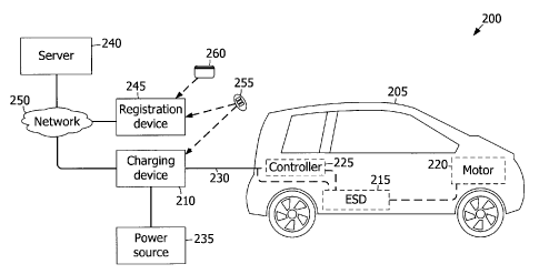
Fig. 2 is a block diagram of an exemplary system 200 for use in charging, or
providing
electricity to, an electrically powered vehicle 205. In an exemplary
embodiment, system
200 includes a charging device 210 coupled to vehicle 205. In the exemplary
embodiment, vehicle 205 includes at least one energy storage device 215, such
as a
battery and/or a capacitor, coupled to a motor 220. Furthermore, vehicle 205
includes a
vehicle controller 225 coupled to energy storage device 215.
In the exemplary embodiment, charging device 210 is removably coupled to
energy
storage device 215 and to vehicle controller 225 via at least one power
conduit 230.
Alternatively, charging device 210 may be coupled to energy storage device 215
and/or
vehicle controller 225 via any other conduit or conduits, and/or charging
device 210 may
be coupled to vehicle controller 225 via a wireless data link (not shown). In
an
exemplary embodiment, power conduit 230 includes at least one conductor (not
shown)
for supplying electricity to energy storage device 215 and/or to any other
component
within vehicle 205, and at least one conductor (not shown) for transmitting
data to, and
receiving data from, vehicle controller 225 and/or any other component within
vehicle
205. Alternatively, power conduit 230 may include a single conductor that
transmits
and/or receives power and/or data, or any other number of conductors that
enables system
-6-
CA 02769942 2012-03-01
247629
200 to function as described herein. Moreover, in an exemplary embodiment,
charging
device 210 is coupled to an electric power source 235, such as a power grid of
an electric
utility company, a generator, a battery, and/or any other device or system
capable of
providing electricity to charging device 210.
In exemplary embodiments, charging device 210 is coupled in communication with
at
least one server 240 and a registration device 245 through a network 250.
Server 240, in
an exemplary embodiment, communicates with charging device 210, for example,
by
transmitting a signal to charging device 210 to authorize payment and/or
delivery of
electricity to energy storage device 215, to access customer information,
and/or to
perform any other function that enables system 200 to function as described
herein.
Network 250 may include, without limitation, the Internet, a local area
network (LAN), a
wide area network (WAN), a wireless LAN (WLAN), a mesh network, a virtual
private
network (VPN), and/or any other network or data connection that enables system
200 to
function as described herein. Charging device 210, controller 225, server 240,
and/or
registration device 245 may be instances of computing device 105 (shown in
Fig. 1). In
an exemplary embodiment, each computing device 105 is coupled to network 225
via
communication interface 140 (shown in Fig. 1). In addition, or alternative to,
registration
device 245 may be integrated with charging device 210.
Registration device 245 may receive information from a wireless transmission
device 255
and/or a payment device 260. For example, wireless transmission device 255 may
include, without limitation, a keyless entry and/or ignition transmitter or
"key fob"
associated with vehicle 205, a garage door opener, a mobile telephone, and/or
any other
device capable of wirelessly transmitting a signal that indicates an
identifier (ID), as
described in more detail below with reference to Fig. 3. Payment device 260
may
include, without limitation, a financial transaction card (e.g., a credit card
or a debit card),
a smart card, a radio frequency identification (RFID) device, a mobile
telephone, and/or
any other device capable of communicating credentials, such as payment account
information (e.g., an account number), to registration device 245. For
example,
-7-
CA 02769942 2012-03-01
247629
registration device 245 may include an input device 130 (shown in Fig. 1) that
receives
credentials from payment device 260. In one embodiment, input device 130
includes a
magnetic stripe reader that reads credentials from a magnetic stripe of
payment device
260. In addition, or alternative to, input device 130 may receive credentials
entered by a
user (e.g., via a keyboard and/or a touch screen).
During operation, in an exemplary embodiment, a user couples energy storage
device 215
to charging device 210 with power conduit 230. The user may interact with
charging
device 210, such as by carrying wireless transmission device 255 within the
proximity of
charging device 210, by initiating a transmission by wireless transmission
device 255,
and/or by accessing a user interface (not shown) of charging device 210 to
enter
information, such as payment information, and/or to initiate power delivery to
energy
storage device 215.
Charging device 210 is configured to communicate with server 240, for example,
to
determine whether wireless transmission device 255 is associated with a
charging
authorization, to authenticate the user, to process the payment information,
and/or to
initiate a transaction based on the electrical energy provided, as described
in more detail
below. If charging device 210 receives a signal from server 240 that indicates
approval
or authorization to deliver power to energy storage device 215, charging
device 210
receives power from electric power source 235 and provides the power to energy
storage
device 215 through power conduit 230.
Charging device 210 communicates with vehicle controller 225 wirelessly,
through
power conduit 230, and/or through any other conduit, to control and/or to
monitor the
delivery of power to energy storage device 215. For example, vehicle
controller 225 may
transmit signals to charging device 210 indicating a charge level of energy
storage device
215 and/or a desired amount and/or rate of power to be provided by charging
device 210.
Moreover, charging device 210 may transmit signals to vehicle controller 225
indicating
an amount and/or rate of electricity being delivered to energy storage device
215.
Additionally or alternatively, charging device 210 and/or vehicle controller
225 may
-8-
CA 02769942 2012-03-01
247629
transmit and/or receive any other signals or messages that enable system 200
to function
as described herein. When energy storage device 215 has been charged to a
desired level,
charging device 210 ceases delivering power to energy storage device 215, and
the user
disengages power conduit 230 from energy storage device 215.
Fig. 3 is a flowchart of an exemplary method 300 for use in charging vehicle
205 (shown
in Fig. 2). Referring to Figs. 2 and 3, in exemplary embodiments, registration
device 245
receives 305 from wireless transmission device 255 a first signal that
indicates a
transmitter identifier (ID). For example, the transmitter ID may be an
alphabetic,
numeric, or alphanumeric value associated with wireless transmission device
255, vehicle
205, and/or a user. In one embodiment, the wireless signal is transmitted by
wireless
transmission device 255 when a user presses a button (e.g., an unlock button
or a lock
button) on wireless transmission device 255. In another embodiment,
registration device
245 receives 305 the wireless signal when wireless transmission device 255 is
proximate
registration device 245. For example, registration device 245 may transmit an
excitation
signal (e.g., an RFID excitation signal), and wireless transmission device 255
may be a
smart key that transmits the wireless signal when in the presence of the
excitation signal
without any action by the user.
Registration device 245 receives 310 an indication that a wireless
transmission device
255 is associated with a user and/or a vehicle that is authorized for charging
via charging
device 210. For example, registration device 245 may receive an authorization
confirmation from a user other than the user of wireless transmission device
255. In one
embodiment, an administrative user verifies the identity of the user
associated with
wireless transmission device 255 and enters an authorization confirmation into
registration device 245.
In other embodiments, registration device 245 receives 307 credentials from
the user
associated with wireless transmission device 255 (e.g., via a keyboard, a
touch screen,
and/or wireless transmission device 255). The credentials may include, without
limitation, an account identifier, a personal identification number (PIN),
and/or any other
-9-
CA 02769942 2012-03-01
247629
information associated with the user. Registration device 245 validates 309
the
credentials, such as by transmitting an authentication request including the
credentials to
server 240 and receiving an authentication response from server 240. In one
embodiment, server 240 stores credentials associated with a collection of
authorized
users. In response to receiving an authentication request, server 240 compares
the
received credentials to the stored credentials and transmits a positive
authentication
response if the two match. The positive authentication response may be
considered an
indication that wireless transmission device 255 is associated with an
authorized user
and/or vehicle. If the received credentials do not match the stored
credentials, server 240
transmits a negative authentication response, in response to which
registration device 245
may terminate method 300.
In addition, or alternative to, the credentials received 307 by registration
device 245 may
include payment account information (e.g., a payment account ID). In such a
scenario,
registration device 245 validates 309 the credentials by determining that the
payment
account ID is associated with a valid payment account. For example,
registration device
245 may determine whether the payment account identifier satisfies one or more
predetermined rules defining the format of the payment account ID (e.g., the
quantity of
digits and/or the value of a check digit). Further, registration device 245
may transmit to
server 240 a payment authorization request including the payment account ID.
Server
240 may communicate with a payment network (e.g., a credit card payment
network
and/or a debit card payment network) to determine whether the payment account
identifier is associated with a valid (e.g., active and in good standing)
payment account.
In response to receiving 310 an indication that wireless transmission device
255 is
associated with an authorized user and/or vehicle, registration device 245
associates 315 a
charging authorization with the transmitter ID received 305 from wireless
transmission
device 255 and/or with an account ID (e.g., a payment account ID) provided by
payment
device 260 and/or a user. Registration device 245 may store the association
itself and/or
transmit the association to server 240, such that a plurality of registration
devices 245
-10-
CA 02769942 2012-03-01
247629
and/or charging devices 210, optionally at a plurality of locations, may
access the
association of the transmitter ID with the charging authorization and/or
account ID (e.g.,
via network 250). Accordingly, system 200 facilitates charging energy storage
device
215 of electric vehicle 205 at a charging device 210 that is remote to
registration device
245 and/or another charging device 210. For example, server 240 may provide
the
charging authorization and/or the account ID to such a charging device 210,
and charging
device 210 may provide electrical energy to vehicle 205, as described below,
based on
the received charging authorization and/or account ID.
In exemplary embodiments, after the charge authorization is associated 315
with the
account ID and/or the transmitter ID, charging device 210 receives 320 from
wireless
transmission device 255 a second signal that, like the first signal, indicates
the transmitter
ID. Charging device 210 determines 325 whether a charging authorization is
associated
with, either directly or indirectly (e.g., via an account ID that is
associated with the
transmitter ID), the transmitter ID. If so, charging device 210 provides 330
electrical
energy to vehicle 205 based on the charging authorization. Otherwise, charging
device
210 may prompt 335 the user (e.g., the operator of wireless transmission
device 255) to
register wireless transmission device 255, as described above, and/or to
provide payment
information (e.g., one-time payment information), such as a payment account
ID.
Method 300 facilitates registering wireless transmission device 255 with
registration
device 245 one time and repeatedly using the charging authorization provided
by such
registration. More specifically, the operator of vehicle 205 may obtain
electrical energy
by presenting wireless transmission device 255 at charging device 210 and/or
initiating a
transmission from wireless transmission device 255 that is received by
charging device
210. Further, as wireless transmission device 255 may be a device associated
with a
function other than charging vehicle 205 (e.g., a keyless entry transmitter, a
keyless
ignition transmitter, a smart key, or a garage door opener), use of system 200
does not
require the operator to carry a device that is specially configured to
interact with charging
device 210 or to present payment credentials each time vehicle 205 is charged.
-11-
CA 02769942 2012-03-01
247629
In exemplary embodiments, method 300 is operable to determine whether charging
of
vehicle 205 is authorized based on the wireless signal received 320 from
wireless
transmission device 255 and to provide 330 electrical energy to vehicle 205
when such
charging is authorized. Some embodiments also facilitate billing an account
that is
associated with wireless transmission device 255. In some such embodiments,
registration device 245 stores a payment account ID in association with the
transmitter
ID, and charging device 210 initiates 340 a transaction (e.g., a financial
transaction)
against the account based at least in part on the quantity of energy provided
330 to
vehicle 205.
In one embodiment, charging device 210 associates with the payment account a
quantity
of electrical energy provided to vehicle 205 and/or a debit based on the
quantity of such
electrical energy. For example, the debit may be expressed as a quantity of
energy (e.g.,
in Joules or kilowatt hours) or as a quantity of currency (e.g., United States
dollars or
euros) that is based on (e.g., equal to the product of) the quantity of energy
and a unit
price of energy.
In some embodiments, charging device 210 determines 327 that the payment
account
identifier is associated with a valid payment account prior to providing
electrical energy
to vehicle 205. For example, charging device 210 may validate the payment
account
identifier and/or payment account information associated with the payment
account
identifier similar to the manner in which registration device 245 validates
309 payment
account credentials, as described above.
Further, in determining 327 whether the payment account is valid, charging
device 210
may determine whether the payment account includes funds sufficient to pay for
an
estimated quantity of electrical energy that will be provided to vehicle 205.
The
estimated quantity may be a predetermined quantity and/or may be based on a
current
charge state of vehicle 205. For example, controller 225 may indicate a
current charge
level and a charge capacity of energy storage device 215. Charging device 210
may
calculate the quantity of energy required to increase the current charge level
to the charge
-12-
CA 02769942 2012-03-01
247629
capacity and calculate a quantity of required funds based on this required
quantity of
energy. In some embodiments, charging device 210 determines whether the
account
includes sufficient funds by requesting a quantity of available funds from
server 240
and/or by transmitting to server 240 a payment authorization request including
the
quantity of required funds. If server 240 responds with an indication that the
account
includes sufficient funds, charging device 210 provides 330 electrical energy
to vehicle
205. Otherwise, charging device 210 may prompt 335 the user to provide payment
information, as described above. In one embodiment, if wireless transmission
device 255
is already associated with a charge authorization, but a payment account
associated with
wireless transmission device 255 is invalid or does not include sufficient
funds, charging
device 210 may also, upon confirmation by the user, associate the newly
entered payment
information (e.g., a payment account identifier) with wireless transmission
device 255,
such that the newly entered payment information may be subsequently used when
charging vehicle 205.
While certain operations are described above with respect to particular
devices, it is
contemplated that any device may perform one or more of the described
operations. For
example, a computing device 105 such as charging device 210 may perform all of
the
operations above.
Embodiments provided herein enable associating a wireless transmission device
with a
vehicle charging authorization using a one-time registration process. The
charging
authorization is later used to allow the energy storage device of an
electrically powered
vehicle to be charged based on the presentation of, or a signal transmission
by, the
wireless transmission device. Such vehicle charging may be performed
repeatedly and/or
at multiple locations (e.g., remote to the registration device and/or other
charging
devices) without requiring subsequent registration. Further, because the
wireless
transmission device may be a device already associated with the vehicle, such
as a key
fob or a garage door opener, the user may not be required to carry a
specialized device for
charging the vehicle.
-13-
CA 02769942 2012-03-01
247629
The methods and systems described herein are not limited to the specific
embodiments
described herein. For example, components of each system and/or steps of each
method
may be used and/or practiced independently and separately from other
components and/or
steps described herein. In addition, each component and/or step may also be
used and/or
practiced with other apparatus and methods.
Some embodiments involve the use of one or more electronic or computing
devices.
Such devices typically include a processor or controller, such as a general
purpose central
processing unit (CPU), a graphics processing unit (GPU), a microcontroller, a
reduced
instruction set computer (RISC) processor, an application specific integrated
circuit
(ASIC), a programmable logic circuit (PLC), and/or any other circuit or
processor
capable of executing the functions described herein. The methods described
herein may
be encoded as executable instructions embodied in a computer readable medium,
including, without limitation, a storage device and/or a memory device. Such
instructions, when executed by a processor, cause the processor to perform at
least a
portion of the methods described herein. The above examples are exemplary
only, and
thus are not intended to limit in any way the definition and/or meaning of the
term
processor.
This written description uses examples to disclose the invention, including
the best mode,
and also to enable any person skilled in the art to practice the invention,
including making
and using any devices or systems and performing any incorporated methods. The
patentable scope of the invention is defined by the claims, and may include
other
examples that occur to those skilled in the art. Such other examples are
intended to be
within the scope of the claims if they have structural elements that do not
differ from the
literal language of the claims, or if they include equivalent structural
elements with
insubstantial differences from the literal languages of the claims.
-14-