Note: Descriptions are shown in the official language in which they were submitted.
CA 02769954 2012-02-28
PREFORM CAVITY INSERT COOLING
FIELD OF THE INVENTION
100011 The invention relates generally to injection molding systems and in
particular to
cooling conduit configurations in a preform mold stack.
BACKGROUND OF THE INVENTION
[0002] In the art of injection molding, a typical injection mold will
contain one or more mold
cores and cavities that correspond to the shape of the molded article being
produced. A melt
stream of moldable material is injected from an injection molding machine into
the mold cavities
through a hot runner system, where it is allowed to solidify for a period of
time before the mold
is opened and the newly molded parts are ejected.
[0003] One of the most significant factors in affecting the overall cycle
time required to
produce one or a plurality of molded articles is the time required to solidify
or cool the newly
molded articles within the mold cavity before the parts are ejected.
[0004] In injection molding applications such as the molding of
polyethylene terephthalate
(PET) preforms, the ability to rapidly cool the molded articles in the mold is
of utmost
importance since the newly molded preforms are in many instances removed from
the mold by a
robotic post-mold cooling device as soon as they have solidified to a point
where they can be
handled without being damaged.
[0005] In PET molding an assembly of components, known in the art as a mold
stack, defines
the mold cavity in which the preform is molded. The inside surface of the
preform is defined by
a mold core, whereas the outside surface of the preform is generally formed in
three sections.
The hemispherical, or otherwise shaped, end portion being defined by a gate
insert, the elongate
body portion being defined by a cavity insert, and the thread/neck portion
being defined by a pair
of cooperating thread splits. Rapid cooling of the outside of the preform is
particularly important
since it is the outside of the preform that is handled by the post-mold cooing
device immediately
upon ejection of the newly molded article from the mold. That being said,
inadequate or
1
CA 02769954 2012-02-28
inefficient cooling of the outside of the preform can result in defective
molded articles, and/or
have a negative impact upon the time of the overall molding cycle.
[0006] As such, a need exists in the art for cooling conduit arrangements
that provides rapid
and efficient cooling to the elongate body portion of the preform.
SUMMARY OF THE INVENTION
[0007] According to an aspect of an embodiment of the present disclosure
there is provided a
preform mold assembly, the preform mold assembly comprising a cavity plate and
a cavity insert
received in a bore in the cavity plate. The cavity insert forms a body portion
of the preform, the
cavity insert defining at least in part an annular decompression chamber for
receiving a supply of
cooling fluid from a cooling fluid inlet and an annular film cooling chamber
in fluid
communication with the annular decompression chamber, wherein the annular film
cooling
chamber delivers a flow of cooling fluid received from the annular
decompression chamber
uniformly along the length of the body portion of the preform.
[0008] According to another aspect of an embodiment of the present
disclosure there is
provided a method of circulating a cooling fluid to cool a body portion of a
preform, the method
comprising the steps of flowing a cooling fluid to a cavity insert inlet,
encircling the body
portion of the preform with the flow of cooling fluid, and creating an annular
film flow of
cooling fluid along the length of the body portion of the preform from the
cooling fluid inlet to a
cooling fluid outlet.
BRIEF DESCRIPTION OF DRAWINGS
[0009] The foregoing and other features and advantages of the invention
will be apparent
from the following description of the invention as illustrated in the
accompanying drawings.
The accompanying drawings, which are incorporated herein and form a part of
the specification,
further serve to explain the principles of the invention and to enable a
person skilled in the
pertinent art to make and use the invention. The drawings are not to scale.
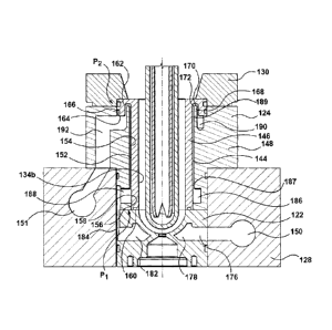
100101 FIG. 1 is a cross-sectional view of a mold stack according to one
embodiment of the
invention.
2
CA 02769954 2012-02-28
=
100111 FIG.
2 is an enlarged view of the mold stack of FIG. 1, detailing the cavity insert
portion.
[0012] FIG.
2A is an enlarged view of the cavity insert of FIG. 2, detailing the chamber
extension feature.
[0013] FIG.
3 is a schematic representation of the cooling fluid flow paths through the
cavity
insert shown in FIGS. I and 2.
[0014] FIG.
4 is an enlarged view of a portion of a mold stack showing an alternate
embodiment of the cavity insert.
[0015] FIG.
5 is an enlarged view of a portion of a mold stack showing a further alternate
embodiment of the cavity insert.
[0016] FIG.
6 is an enlarged view of a portion of a mold stack showing a still further
alternate
embodiment of the cavity insert.
[0017] FIG.
7 is an enlarged view of a portion of a mold stack showing another alternate
embodiment of the cavity insert.
DETAILED DESCRIPTION OF EMBODIMENTS OF THE PRESENT INVENTION
[0018]
Specific embodiments of the present invention will now be described with
reference
to the figures, wherein like reference numbers indicate identical or
functionally similar elements.
The following detailed description is merely exemplary in nature and is not
intended to limit the
invention or the application and uses of the invention. A person skilled in
the relevant art will
recognize that other configurations and arrangements can be used without
departing from the
scope of the invention. In the following description, "downstream" is used
with reference to the
direction of mold material flow from an injection unit to a mold cavity of an
injection molding
system, and also to the order of components or features thereof through which
the mold material
flows from an injection unit to a mold cavity, whereas "upstream" is used with
reference to the
opposite direction. Although the description of the embodiments hereof is in
the context of hot
runner injection molding systems, the invention may also be used in other
molding arrangements
where it is deemed useful. Furthermore, there is no intention to be bound by
any expressed or
3
implied theory presented in the preceding technical field, background, brief
summary or the
following detailed description.
[0019] FIG. 1 is a sectional view of a mold stack assembly according to an
exemplary
embodiment of the invention. A plurality of such mold stacks 100 are arranged
within an injection
molding system, in an array which corresponds to the number of preforms being
molded during
each injection molding cycle. Each mold stack 100 is concentric about a
central axis 102. Mold
stack 100 can be generally divided into a core assembly 104 and a cavity
assembly 106, separable
along a parting line PL, each of which are associated with a respective core
half and cavity half of
an injection molding system. Core assembly 104 and cavity assembly 106
cooperate to define a
mold cavity 108 in which the molded article is formed.
[0020] Core assembly 104 of mold stack 100 generally includes a mold core
110, a core support
112 and a split thread insert comprised of first half 114a and second half
114b. Mold core 110 is
generally cylindrical and provides a cooling mechanism, such as a bubbler tube
116 in fluid
communication with suitable supply/return cooling channels 118 provided in
core plate 120. A
cooling fluid is circulated through bubbler tube 116, so as to cool the
temperature of mold core
110, thereby assisting in the solidification of the melt stream of moldable
material injected into
mold cavity 108. Split thread insert 114a11 14b, which provides the molding
surface for the taper
and thread region of the preform, also generally comprises a cooling
mechanism. For example,
each half of the split thread insert 114a/114b may be provided with a cooling
circuitry similar to
that disclosed in US 5,599,567. As is generally known in the art, split thread
insert 114a/114b is
configured to be actuated by sliders or similar mechanism (not shown) mounted
on a stripper plate
(also not shown) to translate forwardly and/or laterally during preform
ejection.
[0021] Cavity assembly 106 of mold stack 100 generally includes a gate
insert 122 and a cavity
insert 124 located in series within a bore 126 extending through a cavity
plate 128. The cavity
assembly may also include an alignment ring 130 to assist in aligning the
cavity assembly 106 to
the core assembly 104. Gate insert 122 defines a mold gate 132 at the upstream
end of the mold
cavity 108. Downstream of mold gate 132, gate insert 122 defines a molding
surface 134a,
forming what is generally the terminal end of a molded preform article molded
in mold
4
CA 2769954 2018-07-31
CA 02769954 2012-02-28
=
cavity 108. Downstream face 136 of gate insert 122 is configured to engage the
upstream face
138 of cavity insert 124, whereby gate insert 122 and cavity insert 124
concentrically align
relative to central axis 102.
100221 Cavity insert 124, in cooperation with mold core 110 define the
cylindrical body
portion of mold cavity 108. The cavity insert 124 exemplified herein is
generally defined by a
body portion 140, and a flange portion 142. Body portion 140 of cavity insert
124 extends in a
downstream direction perpendicular to upstream face 138 with flange portion
142 generally
extending from said body portion 140.
[0023] Turning now to FIG. 2, shown is an enlarged view of cavity insert
124. In the
embodiment shown, cavity insert 124 includes two cavity subcomponents, namely
inner portion
146 and outer sleeve 148, where inner portion 146 is coaxially received by
outer sleeve 1,48.
The arrangement of inner portion 146 and outer sleeve 148 establishes a
largely continuous
annular cavity insert cooling chamber 144 therebetween, cavity insert cooling
chamber 144 in
fluid communication with corresponding cooling fluid supply/return channels,
for example
channel 150/151 provided in cavity plate 128. A cooling fluid is circulated
through cavity insert
cooling chamber 144 so as to cool the temperature of cavity insert 124,
thereby assisting in the
solidification of the melt stream of moldable material. In particular, inner
portion 146 is
provided with an outside surface 152 having an outer diameter that is less
than the inner diameter
of surface 154 of outer sleeve 148. Outer sleeve 148 is seated relative to the
overall mold stack
by virtue of its placement within the surrounding cavity plate 128. Inner
portion 146 defines
molding surface 134b, and is seated relative to the overall mold stack 100 by
virtue of
engagement with outer sleeve 148 at points P1 and P2. As shown at P1, an
outside contact
surface 156 towards the upstream end of inner portion 146 is dimensioned to
seat and engage an
inside contact surface 158 of outer sleeve 148. Inner portion 146 is generally
provided with
suitable sealing features to ensure that cooling fluid is retained within
cooling chamber 144. For
example, as shown in FIG. 2, an o-ring may be provided in a groove 160
situated on an end
surface of inner portion 146, so as to provide a sealing effect when engaged
with the adjacently
positioned gate insert. At P2, the downstream region of inner portion 146 is
provided with a
flange 162 that seats within a corresponding bore 164 in outer sleeve 148.
Flange 162 is also
generally provided with suitable sealing features to ensure that cooling fluid
is retained within
CA 02769954 2012-02-28
cooling chamber 144. For example, an o-ring may be provided in a groove 166 to
ensure a
=
sealed cooling chamber 144. Flange 162 further serves to axially locate
alignment ring 130.
Alignment ring 130 ensures proper axial alignment between the halves of split
thread insert
114a/114b, and subsequently core assembly 104 and cavity assembly 106 of mold
stack
assembly 100, by way of interfaced tapers shown at T1/T2 (see FIG. 1).
100241 Cooling of preforms in the vicinity of the neck/taper region is
a difficult task with
many mold stack configurations. In general, cooling of the neck/tapered region
is accomplished
by way of the split thread insert. In the embodiment represented in FIGS. 1
and 2, further
enhancement of the cooling effect in the neck/tapered region is achieved by
extending cooling
chamber 144 along substantially the entire length of the cavity insert 124. To
achieve this, and
referring now to FIG. 2A, outer sleeve 148 is provided with a chamber member
168 that
positions within a corresponding recess 170 in the downstream portion of
cavity insert 124
adjacent the split thread insert, for example in flange 162 of inner portion
146. Chamber
member 168 is configured with outside surfaces 161a/161b being dimensionally
smaller than the
inside walls 163a/163b of corresponding recess 170 in flange 162, thereby
defining a chamber
extension connected in fluid communication to cooling chamber 144, through
which cooling
fluid is able to flow. For the discussion provided herein, the chamber
extension is generally
referred to as a hairpin chamber 172, having a generally annular hairpin or
double-backed
shaped configuration. As such, cooling fluid that flows through cavity insert
124 is directed not
only through the main cooling chamber 144 of the elongated body portion, but
also through a
first chamber extension portion 165a, a radial chamber extension portion 165b,
and a second
chamber extension portion 165c, thereby defining the annular loop structure of
hairpin chamber
172 adjacent to the split thread insert.
[0025] Flow of cooling fluid through cavity assembly 106, and
specifically cavity insert
cooling chamber 144 is primarily in the form of film flow. Cooling fluid flow
may proceed in
either direction through cooling chamber 144, depending on the configuration
of the associated
cooling fluid supply/return lines. Regardless, to promote film flow through
cooling chamber
144, provided in fluid communication, and in relation to at least one end of
cooling chamber 144
is a decompression chamber, the details of which are presented below. As will
be appreciated,
the decompression chamber is connected in fluid communication to at least the
end of cooling
6
CA 02769954 2012-02-28
=
chamber 144 representing the input side, that is the side where cooling fluid
is entering cooling
chamber 144. To accommodate cooling fluid flow in either direction, and in
some cases to
generally enhance overall film flow through the annular cooling chamber, the
cavity insert will
have two decompression chambers, one connected in fluid communication to each
end of
cooling chamber 144, that is in relation to each of the input and output ends.
100261 As
indicated above, in a mold stack arrangement, cooling fluid may be configured
to
flow in either the upstream or downstream direction, depending on the
configuration of the
cooling fluid supply lines, and the manner of directing cooling fluid to
respective cooling
channels. For this explanation, reference will be made to a mold stack in
which cooling fluid
flows in the downstream direction; that is in the same general direction as
the melt flow through
cavity 108. The following explanation will also exemplify an arrangement where
cooling fluid
flows serially through gate insert 122 and cavity insert 124. Having regard to
FIG. 2, a flow of
cooling fluid from a cooling channel 150 provided for in cavity plate 128
enters gate insert 122
through an inlet channel 176 which extends from the outside diameter of gate
insert 122 to gate
insert cooling chamber 178. Cooling chamber 178 circumscribes the gate insert
molding surface
and may generally correspond to the shape thereof, depending on the cooling
circuit
configuration chosen for gate insert 122. At a location generally
diametrically opposite inlet
channel 176 the flow of cooling fluid leaves cooling chamber 178 though outlet
182. On exit
from gate insert 122, at outlet 182 cooling fluid then flows through a bridge
channel 184 which
fluidly connects gate insert 122 to cavity insert 124. From bridge channel
184, cooling fluid
then flows through at least one radial cooling fluid channel 188 and enters
into a first
decompression chamber 186 between inner sleeve 146 and outer sleeve 148.
First
decompression chamber 186 is generally an annular channel on an inside surface
of the outer
sleeve, and is sized such that cooling fluid is able to substantially fill and
encircle first
decompression chamber 186 before flowing into a first end 187 of cooling
chamber 144.
Cooling chamber 144 extends substantially along the entire length of cavity
insert 124 and has a
cross-sectional area that is substantially smaller than that of first
decompression chamber 186,
such that in comparison with first decompression chamber 186, cooling chamber
can be
considered an annular compression cooling chamber. This relative difference in
cross sectional
area between first decompression chamber 186 and cooling chamber 144 promotes
film flow of
cooling fluid through cooling chamber 144, wherein substantially the entire
annular chamber is
7
CA 02769954 2012-02-28
in contact with a substantially uniform flow of cooling fluid. From a second
end 189 of annular
cooling chamber 144, the cooling fluid generally flows into hairpin chamber
172 and into a
second decompression chamber 190 provided as an annular channel on a
downstream surface of
the outer sleeve 148, at an interface between the outer sleeve 148 and the
inner portion 146.
Second decompression chamber 190 is connected to fluidly communicate with
return line 192
which allows cooling fluid to exit cavity insert 124 into a return line 151
provided in cavity plate
128.
[0027] To illustrate the decompression/compression zones provided by the
various chambers
described above, presented in FIG. 3 is a representation of the cooling fluid
flow path defined by
the above arrangement. As shown, on flow of the cooling fluid through bridge
channel 184, the
cooling fluid enters first decompression chamber 186 through radial cooling
fluid channel 188,
wherein by virtue of the compression differential with the downstream cooling
chamber 144, the
cooling fluid substantially fills first decompression chamber 186 and
encircles the upstream
portion of the cavity insert. The cooling fluid then proceeds to flow into
cooling chamber 144,
where the cooling flows along the length of cavity insert 124 in substantially
film flow. In this
respect, film flow is defined as a generally uniform flow of cooling fluid in
all regions of the
cavity insert cooling chamber in the direction from the inlet, to the outlet.
In this way, regions of
reduced heat transfer arising from stagnated cooling fluid flow are reduced,
increasing the
overall cooling efficiency of the cavity insert. Towards the downstream end of
cooling chamber
144, the cooling fluid passes through hairpin chamber 172 and enters second
decompression
chamber 190. From second decompression chamber 190, the cooling fluid
continues to flow
through return line 192 back to cavity plate 128.
100281 An advantage of the largely continuous annular cavity insert cooling
chamber
arrangement described above is the overall wetting surface and uniformity of
cooling fluid flow
is increased when compared to prior art cavity inserts wherein the cooling
chamber is comprised
of a groove arranged on the outer surface of the insert through which a
cooling fluid flows. By
providing a decompression chamber prior to flow of the cooling fluid through
the cavity insert
124, film flow of the cooling fluid around the entire circumference of the
cooling chamber 144 is
promoted, thereby reducing hotspots by reducing regions of stagnant cooling
fluid flow.
8
CA 02769954 2012-02-28
100291 As mentioned briefly above, the supply of cooling fluid to the mold
stack
arrangement could be in either the upstream or downstream direction, depending
on the
configuration of the cooling fluid supply lines, and the manner of directing
cooling fluid to
respective cooling channels. In the exemplary embodiment discussed above,
cooling fluid is
described as flowing in the downstream direction. As will be appreciated,
where the cooling
fluid flow through cavity insert 124 is opposite to that described above, that
is in the upstream
direction, second decompression chamber 190 provides the same functionality as
first
decompression chamber 186. In other words, on upstream cooling fluid flow
through cavity
insert 124, second decompression chamber 190 serves to promote film flow
through cavity
chamber 144.
[00301 Referring now to FIG. 4, shown is another embodiment of cavity insert
424 according
to the present invention. In the description of this embodiment, the previous
embodiment
detailed in FIGS. 1 and 2 can be referenced for additional description of like
parts, as only
differences are discussed in detail below. Features and aspects described in
other embodiments
can be used accordingly with the present embodiment, and visa versa.
[00311 Cavity assembly 406 includes a gate insert 422 and cavity insert 424
located in series
within a bore 426 extending through a cavity plate 428. Cavity insert 424 is
similar to cavity
insert 124 described above, with one exception that cavity insert 424 excludes
the hairpin
channel feature. As such, in the arrangement shown, cavity insert cooling
chamber 444, formed
through the coaxial arrangement of inner portion 446 and outer sleeve 448, is
connected to
fluidly communicate directly with first decompression chamber 486 at first end
487, and second
decompression chamber 490 at second end 489. The embodiment of FIG. 4 also
provides a
variation on the arrangement of first decompression chamber 486 and second
decompression
chamber 490 where these features are formed generally as an annular channel on
the outer
surface of the inner portion 446. As such, the decompression chambers 486/490
are provided
between inner portion 446 and outer sleeve 448. With this arrangement, that is
with first
decompression chamber 486 provided between inner portion 446 and outer sleeve
448, first
decompression chamber 486 is connected in fluid communication with bridge
channel 484 by
way of radial cooling fluid channel 488. On the opposite end of cavity insert
cooling chamber
444, second decompression chamber 490 is connected so as to provide direct
fluid
9
CA 02769954 2012-02-28
. .
communication with return line 492. In all other respects, the structural and
functional
characteristics of cavity insert 424 are the same as those described above for
the embodiment
shown in FIGS. 1 and 2.
[0032] Referring now to FIG. 5, shown is another embodiment of cavity
insert 524 according
to the present invention. In the description of this embodiment, the
embodiment detailed in
FIGS. 1 and 2 can be referenced for additional description of like parts, as
only differences are
discussed in detail below. Features and aspects described in other embodiments
can be used
accordingly with the present embodiment, and visa versa.
[0033] Cavity assembly 506 includes a gate insert 522 and cavity insert
524 located in series
within a bore 526 extending through a cavity plate 528. Unlike the cavity
inserts detailed in the
previous embodiments, cavity insert 524 is a one-piece component comprised of
a cavity insert
body 529. In this form, cavity insert body 529 is configured to seat directly
within mold plate
528, and by virtue of cavity insert body 529 having at least a portion of an
outside surface 542
with an outer diameter that is less than the inner diameter of surface 554 of
bore 526, cavity
insert cooling chamber 544 is formed therebetween.
[0034] Cavity insert cooling chamber 544 is connected to fluidly
communicate directly with
first decompression chamber 586 at a first end 587 and second decompression
chamber 590 at a
second end 589. First decompression chamber 586 and second decompression
chamber 590 are
generally provided as annular channels formed into bore 526 of cavity plate
528. As such, the
decompression chambers 586/590 are provided between cavity insert 524 and mold
plate 528.
With this arrangement, that is with first decompression chamber 586 formed
into bore 526 of
cavity plate 528, first decompression chamber 586 is connected so as to
fluidly communicate
directly to bridge channel 584. On the opposite end of cavity insert cooling
chamber 544,
second decompression chamber 590 is connected so as to fluidly communicate
directly to return
line 592. In all other respects, the structural and functional characteristics
of cavity insert 524
are generally the same as those described above for the previous embodiments.
[0035] Referring now to FIG. 6, shown is another embodiment of cavity
insert 624 according
to the present invention. In the description of this embodiment, the
embodiment detailed in
FIGS. 1 and 2 can be referenced for additional description of like parts, as
only differences are
CA 02769954 2012-02-28
. .
discussed in detail below. Features and aspects described in other embodiments
can be used
accordingly with the present embodiment, and visa versa.
[0036] Cavity assembly 606 includes a gate insert 622 and cavity insert
624 located in series
within a bore 626 extending through a cavity plate 628. Unlike the cavity
inserts detailed in the
FIGS. 1 through 4, and similar to that detailed in FIG. 5, cavity insert 624
is a one-piece
component comprised of a cavity insert body 629. In this form, cavity insert
body 629 is
configured to seat directly within mold plate 628, and by virtue of cavity
insert body 629 having
at least a portion of an outside surface 642 with an outer diameter that is
less than the inner
diameter of surface 654 of bore 626, cavity insert cooling chamber 644 is
formed therebetween.
[0037] Cavity insert cooling chamber 644 is connected to fluidly
communicate directly with
first decompression chamber 686 at first end 687 and second decompression
chamber 690 at
second end 689. Unlike the embodiment shown in FIG. 5, first decompression
chamber 686 and
second decompression chamber 690 are generally provided as annular channels
formed into an
outside surface of cavity insert 624. As such, the decompression chambers
686/690 are provided
between cavity insert 624 and mold plate 628. With this arrangement, that is
with first
decompression chamber 686 formed into an outside surface of cavity insert 624,
first
decompression chamber 686 is connected so as to fluidly communicate directly
to bridge
channel 684. On the opposite end of cavity insert cooling chamber 644, second
decompression
chamber 690 is connected so as to fluidly communicate directly to return line
692. In all other
respects, the structural and functional characteristics of cavity insert 624
are generally the same
as those described above for the previous embodiments.
[0038] Referring now to FIG. 7, shown is a further embodiment of cavity
insert 724
according to the present invention. In the description of this embodiment, the
embodiment
detailed in FIGS. 1 and 2 can be referenced for additional description of like
parts, as only
differences are discussed in detail below. Features and aspects described in
other embodiments
can be used accordingly with the present embodiment, and visa versa.
[0039] Cavity assembly 706 includes a gate insert 722 and cavity insert
724 located in series
within a bore 726 extending through a cavity plate 728. Unlike the cavity
inserts detailed in the
FIGS. 1 through 4, and similar to that detailed in FIGS. 5 and 6, cavity
insert 724 is a one-piece
11
CA 02769954 2012-02-28
component comprised of a cavity insert body 729. In this form, cavity insert
body 729 is
configured to seat directly within mold plate 728, and by virtue of cavity
insert body 729 having
at least a portion of an outside surface 742 with an outer diameter that is
less than the inner
diameter of surface 754 of bore 726, cavity insert cooling chamber 744 is
formed therebetween.
[0040] Cavity insert cooling chamber 744 is connected to fluidly
communicate with first
decompression chamber 786 and second decompression chamber 790. In the
embodiment
shown, first decompression chamber 786 is generally provided as an annular
channel formed into
bore 726 of cavity plate 728. Second decompression chamber 790 is provided as
an annular
channel on a downstream surface of cavity plate 728, at an interface between
cavity plate 728
and cavity insert body 729. As shown. second decompression chamber 790 is
connected so as to
fluidly communicate to return line 792 which allows cooling fluid to exit
cavity insert 724. As
such, the decompression chambers 786/790 are provided between cavity insert
724 and mold
plate 728. Although not detailed here, the decompression chambers may
alternatively be formed
in the cavity insert, as shown in the embodiment detailed in FIG. 6. In
addition, the embodiment
shown in FIG. 7 provides a hairpin chamber 772 similar to that provided in the
embodiment of
FIGS. 1, 2 and 2A. To achieve this, cavity plate 728 is provided with a
chamber member 768
that positions within a corresponding recess 770 in a downstream region of
cavity insert body
729, for example flange 762. Chamber member 768 is configured to be
dimensionally smaller
than the corresponding recess 770 in flange 762, thereby defining a chamber
extension
connected in fluid communication to cooling chamber 744, through which cooling
fluid is able
to flow. For the discussion provided herein, the chamber extension is
generally referred to as a
hairpin chamber 772, having a generally annular hairpin or double-backed
shaped configuration.
As such, cooling fluid that flows through cavity insert 724 is directed not
only through the main
cooling chamber 744 of the elongated body portion, but also the annular loop
structure of hairpin
chamber 772 adjacent to the split thread inserts. In all other respects, the
structural and
functional characteristics of cavity insert 724 are generally the same as
those described above for
the previous embodiments.
[0041] It will be understood that all components of the mold stack assembly
described herein
may be made of suitable material commonly used in injection molding devices.
For instance,
certain components may be made of conventional tool steel, stainless steel, or
other suitable
12
material that is able to withstand changes in temperature or thermal shock,
which may occur as a
result of the continuous cycling between extreme hot and cold temperatures.
Thermally
conductive materials may also be implemented where suitable. Some examples of
suitable
materials for use in constructing the cavity insert include but are not
limited to: copper and copper
alloys, for example beryllium copper (MOLDMAX beryllium copper alloys, C17000
alloys) and
beryllium free copper (AMPCO 940, C18000), aluminum and aluminum alloys,
molybdenum and
molybdenum alloys (TZM). It will also be understood that the components of the
cavity insert,
that is inner portion 146 and outer sleeve 148 may be permanently coupled,
i.e., fixed or rigidly
attached, such as by metallurgic bonding (e.g. brazing, soldering), or shrink
fitting, or removably
coupled, such as by press fitting.
[0042] While
various embodiments according to the present invention have been described
above, it should be understood that they have been presented by way of
illustration and example
only, and not limitation. It will be apparent to persons skilled in the
relevant art that various
changes in form and detail can be made therein without departing from the
scope of the invention.
Thus, the breadth and scope of the present invention should not be limited by
any of the above-
described exemplary embodiments, but should be defined only in accordance with
the appended
claims and their equivalents. It will also be understood that each feature of
each embodiment
discussed herein, and of each reference cited herein, can be used in
combination with the features
of any other embodiment.
13
CA 2769954 2018-07-31