Note: Descriptions are shown in the official language in which they were submitted.
CA 02770006 2012-03-05
TITLE: "METHOD AND APPARATUS FOR FLUID PUMPING"
BACKGROUND OF THE INVENTION
1. Field of the Invention
The present invention pertains to a hydraulic pumping unit. More particularly,
the
present invention pertains to a hydraulic pumping unit that provides precise
rod speed
control with minimal maintenance requirements.
2. Brief Description of the Prior Art
Liquid-producing subterranean reservoirs all have some level of energy or
potential, frequently referred to as "reservoir pressure" that will force
fluid (liquid, gas or
a mixture) to areas of lower energy or potential. If a well penetrates such a
reservoir,
and if the pressure inside such a well is decreased below the reservoir
pressure, fluids
will feed into the well from said formation. However, depending on the depth
of the
reservoir and density of the fluid(s), the reservoir may not have sufficient
reservoir
pressure to push the fluid to the surface. The deeper the well, or the heavier
the
fluid(s), the higher the reservoir potential that is required to push such
fluid(s) to the
surface.
Many hydrocarbon producing reservoirs have sufficient potential to naturally
produce oil and gas (which are relatively light, compared to water) during the
early
stages of production. However, as a well continues to produce, reservoir
pressure will
often decrease as a reservoir depletes. Further, in many reservoirs, formation
water will
eventually encroach into the wellbore, causing the lifting requirements to be
much
-1-
CA 02770006 2012-03-05
greater than for just oil and/or gas. Either or both of these conditions can
cause
production from a well to decline, or possibly even cease entirely.
As a result of the foregoing, artificial means are often used to continue or
increase the flow of liquids (such as crude oil, water or a mix of oil and
water) from
subterranean reservoir(s) to the earth's surface. As noted above, such
"artificial lift"
can be required when insufficient reservoir pressure exists to lift produced
fluids to the
surface in a well. Artificial lift can also be employed in flowing wells to
increase the flow
rate above what would occur naturally.
Although numerous different means of artificial lift exist, one common type
involves the use of a mechanical device known as a "rod pump" inside a well.
Such rod
pumps, which are well known to those having skill in the art, are typically
elongate
cylinders with both fixed and moveable elements. Such rod pumps are designed
to be
installed down-hole inside of wells, at or near the depth of the reservoir(s)
from which
production is obtained, to gather fluids from below and lift said fluids
within the wells to
the surface. In many instances, such down-hole pumps have a barrel equipped
with
two ball check valves: a stationary valve near the bottom of said barrel, and
a traveling
valve that moves up and down. As reservoir fluids enter a well from a down-
hole
reservoir(s), the down-hole pump lifts such fluids from said subterranean
reservoir(s) to
the surface within said well.
Rod pump systems generally comprise a reciprocating down-hole pump situated
within a well at or near a subterranean reservoir, an above-ground drive
mechanism at
the earth's surface, and a length of elongate cylindrical rods (frequently
referred to as
"sucker rods") connecting said down-hole pump to said surface drive mechanism
in said
-2-
CA 02770006 2012-03-05
well. In many conventional installations, said surface drive mechanism
comprises a
pump-jack (also sometimes referred to as a pumping unit, horsehead pump,
rocking
horse, beam pump, or jack pump) that converts rotary motion (from an electric
motor or
internal combustion engine, for example) to a reciprocating vertical motion in
order to
drive a reciprocating down-hole pump via the sucker rods. Such pump-jacks
generally
exhibit a characteristic nodding motion.
Although very common, conventional pump-jacks and other types of surface
drive mechanisms suffer from a number of significant shortcomings. Said
surface drive
mechanisms can be large, cumbersome and difficult to install in many
instances.
Further, such conventional surface drive mechanisms are typically complicated,
and
expensive to manufacture, operate and maintain.
Thus, there is a need for a pumping apparatus having a surface drive mechanism
that is relatively inexpensive, durable and simple to operate. The hydraulic
pumping
apparatus should provide precise rod speed control with minimal maintenance
requirements, while permitting stroke speed to be easily and quickly adjusted
without
the need for expensive, troublesome or complicated electronic equipment.
SUMMARY OF THE PRESENT INVENTION
The present invention comprises a hydraulic pumping apparatus having an
improved surface drive mechanism. By way of illustration and not limitation,
the present
invention is described herein as a hydraulic pumping apparatus installed on a
well for
pumping fluids from subterranean formations. However, it is to be observed
that the
hydraulic pumping apparatus of the present invention, and components thereof,
can be
-3-
CA 02770006 2012-03-05
used in many different applications involving the pumping of fluid(s) beyond
the
particular embodiment described herein.
In a preferred embodiment, the hydraulic pumping apparatus of the present
invention comprises an elongate tower assembly that can be mounted at the
surface of
a well. Said tower assembly provides a rigid frame for supporting at least one
hydraulic
cylinder assembly that is oriented substantially parallel to said tower
assembly. In the
preferred embodiment, said elongate tower assembly (and the at least one
hydraulic
cylinder assembly supported therein) are mounted in substantially axial
alignment over
said well at the earth's surface. Said at least one hydraulic cylinder
assembly is
connected to a bridle assembly attached to a polished rod; said polished rod
is, in turn,
connected to a length of interconnected sucker rods that extend into said
well. A down-
hole pump mechanism is mounted near the bottom of said well and is attached to
the
distal end of said sucker rods.
Said at least one hydraulic cylinder assembly can be beneficially mounted to
said
elongate tower assembly using a self-centering pivot mounting assembly. Said
self-
centering pivot mounting assembly ensures that said at least one hydraulic
cylinder
assembly finds the center of gravity, thereby preventing unwanted side loading
on said
at least one cylinder assembly.
A prime mover assembly provides hydraulic fluid used to actuate said at least
one hydraulic cylinder assembly. Hoses or other conduits connect said prime
mover to
a wedge spool valve disposed between said prime mover and said at least one
cylinder
assembly. Said wedge spool valve can be used to control the stroking of said
at least
-4-
CA 02770006 2012-03-05
one hydraulic cylinder assembly and, in turn, the reciprocation of said sucker
rods in
and out of said well.
The hydraulic pumping apparatus of the present invention is inexpensive,
durable
and simple to operate. Further, the hydraulic pumping apparatus of the present
invention has a small footprint and can be directly mounted to wells having
shallow to
medium depths or, alternatively, skid supported for wells extending to deeper
depths.
The hydraulic pumping apparatus of the present invention further provides for
precise
rod speed control with minimal maintenance requirements. Stroke speed can be
easily
and quickly adjusted without the need for expensive, troublesome or
complicated
electronic equipment.
BRIEF DESCRIPTION OF THE DRAWINGS
The foregoing summary, as well as the following detailed description of the
preferred embodiments, is better understood when read in conjunction with the
appended drawings. For the purpose of illustrating the invention, the drawings
show
certain preferred embodiments. It is understood, however, that the invention
is not
limited to the specific methods and devices disclosed. Further, dimensions,
materials
and part names are provided for illustration purposes only and not limitation.
FIG. 1 depicts a front perspective view of the support tower of the hydraulic
pumping apparatus of the present invention.
FIG. 2 depicts a front perspective view of the support tower of the hydraulic
pumping apparatus of the present invention including an optional support base.
-5-
CA 02770006 2012-03-05
FIG. 3 depicts a front view of the hydraulic pumping apparatus of the present
invention installed on a well.
FIG. 4 depicts a side view of the support tower of the hydraulic pumping
apparatus of the present invention installed on a well.
FIG. 5 depicts a rear view of the hydraulic pumping apparatus of the present
invention installed on a well.
FIG. 6 depicts a side sectional view of the wedge spool control valve of the
present invention.
FIG. 7 depicts a side view of the distal end of the wedge spool member of the
wedge spool control valve of the present invention.
FIG. 8 depicts and end view of the distal end of the wedge spool member of the
wedge spool control valve of the present invention.
FIG. 9 depicts a detailed view of the highlighted area shown in FIG. 6.
FIG. 10 depicts a sectional view of the wedge spool control valve of the
present
invention along line 10-10 of FIG. 9.
FIGS. 11 through 14 depict sequential side sectional views of operation of the
wedge spool control valve of the present invention.
FIG. 15 depicts a side sectional view of a double seal system for the cylinder
rod
assembly of the present invention.
FIG. 16 depicts a side sectional view of a double seal system and fluid drain
mechanism for the cylinder rod assembly of the present invention.
FIG. 17 depicts a side view of the self-centering cylinder mounting assembly
of
the present invention.
-6-
CA 02770006 2012-03-05
FIG. 18 depicts a side sectional view of a cylindrical fluid reservoir of the
present
invention.
FIG. 19 depicts a side sectional view of a zero restriction check valve
assembly
of the present invention.
FIG. 20 depicts a side sectional view of an alternative embodiment of a zero
restriction check valve assembly of the present invention.
FIG. 21 depicts a schematic view of one embodiment of a motor skid of the
present invention having an electric regeneration system.
FIG. 22 depicts a schematic view of an alternative embodiment of a motor skid
of
the present invention not equipped with an electric regeneration system.
FIG. 23 depicts a schematic view of one embodiment of a motor skid of the
present invention having an internal combustion engine.
DETAILED DESCRIPTION OF A PREFERRED EMBODIMENT OF THE INVENTION
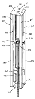
Referring to the drawings, FIG.1 depicts a front perspective view of support
tower
assembly 200 of hydraulic pumping apparatus 10 of the present invention.
Elongate
support tower assembly 200 is capable of being mounted to the upper end of a
well that
extends into the earth's crust. Said tower assembly 200 has substantially
planar upper
plate member 201 having optional central aperture 205, lower substantially
planar plate
member 202 having cut-out section 203 and elongate column support members 204
extending between said upper and lower plate members. Support tower assembly
200
provides a rigid support frame for supporting at least one hydraulic cylinder
assembly
300. In the preferred embodiment, said elongate tower assembly 200 (and said
at least
-7-
CA 02770006 2012-03-05
one hydraulic cylinder assembly 300 supported therein) are mounted in
substantially
axial alignment over a well.
As depicted in FIG. 1, tandem cylinder assemblies 300 are mounted within
support tower assembly 200. Each of said hydraulic cylinder assemblies 300 has
a
barrel 301 and an extendable piston rod 302 movably disposed in said barrel
301;
because said hydraulic cylinder assemblies 300 are depicted in the retracted
position in
FIG. 1, piston rods 302 are not fully visible in FIG. 1. Cylinder barrels 301
are attached
to upper plate member 201. In the embodiment depicted in FIG. 1, conventional
bolted
faster means 303 are used to connect said cylinder assemblies 300 to upper
plate
member 201; however, it is to be observed that pivot mounting assemblies
depicted in
FIG. 17 (described below) can be beneficially used for mounting said cylinder
assemblies.
Spreader bar or bridle assembly 310 is connected to the distal end of each
piston
rod 302. Said bridle assembly 310 is attached to polished rod 320 using clamp
member
321. Polished rod 320 is, in turn, connected to a length of interconnected
sucker rods
322 that extends into a well (not shown in FIG. 1). Although not depicted in
FIG. 1, it is
to be understood that said sucker rods extend into said well, and connect to a
down-
hole pump situated at or near subterranean reservoir(s) from which fluid(s)
are to be
produced. Stop angle 312 and valve mounting plate 313 can also be mounted at
desired locations within tower support tower assembly 200.
FIG. 2 depicts a front perspective view of support tower assembly 200 of
hydraulic pumping apparatus 10 of the present invention including optional
support base
assembly 210. Said tower assembly 200 has substantially planar upper plate
member
-8-
CA 02770006 2012-03-05
201 with optional central aperture 205, lower substantially planar plate
member 202
having cut-out section 203 and elongate column support members 204 extending
between said upper and lower plate members and providing structural support
for tower
assembly 200.
Tandem cylinder assemblies 300 are mounted within support tower assembly
200. Each of said hydraulic cylinder assemblies 300 has a barrel 301 and an
extendable piston rod 302 movably disposed in said barrel 301. Cylinder
barrels 301 are
attached to upper plate member 201 with fasters 303, while the distal ends of
piston rod
members 302 are connected to bridle assembly 310.
Support base assembly 210 has a plurality of adjustable leg members 211. Each
of said leg members 211 further has a substantially planar foot pad 212 to
ensure
stability of said support base assembly. Support base assembly 210 can be used
to
provide additional stability and support to tower assembly 200 when said tower
assembly 200 is mounted on a well. In such instances, support base assembly
210
prevents all loading from being placed on a well equipped with hydraulic
pumping
apparatus 10, and instead transfers much of said loading (especially axial
loading) to
support base assembly 210. Although said support base assembly is depicted as
having three leg members 211 (i.e., a tripod), it is to be observed that
configurations
having different numbers of leg members can also be used. Further, tie rods or
other
similar structural supports can be added as may be required.
FIG. 3 depicts a front view of hydraulic pumping apparatus of the present
invention installed on a well 20 having wellhead 22 and flow lines 21. Tower
assembly
200 has substantially planar upper plate member 201, lower substantially
planar plate
-9-
CA 02770006 2012-03-05
member 202 and elongate column support members 204 extending between said
upper
and lower plate members and providing structural support for tower assembly
200.
Tandem cylinder assemblies 300 are mounted within support tower assembly
200 in substantially parallel orientation. Each of said hydraulic cylinder
assemblies 300
has a barrel 301 and an extendable piston rod 302 movably disposed in said
barrel 301.
As depicted in FIG. 3, cylinder barrels 301 are attached to upper plate member
201 with
fasters 303, while the distal ends of piston rod members 302 are connected to
bridle
assembly 310. Bridle assembly 310 is attached to polished rod 320 using clamp
member 321.
Polished rod 320 is movably disposed through dynamically sealing stuffing box
220 situated over well 20, and extends into wellhead 22 in a manner known to
those
having skill in the art. Although not shown in FIG. 3, polished rod 320 is
connected to a
length of interconnected sucker rods as described above which extend in said
well to a
down-hole reciprocating rod pump. Prime mover assembly 400 is connected to
support
tower assembly 200 via hydraulic hose 410.
As hydraulic cylinder assemblies 300 are actuated, bridle assembly 310 can be
raised and lowered within tower assembly 200. Such raising and lowering of
bridle
assembly 310 imparts a reciprocating motion to polished rod 320 (and attached
components) within well 20. Stuffing box 220 provides a dynamic seal against
polished
rod 320, causing pumped well fluids to exit said well via flow lines 21,
rather than out
the top of wellhead 22. Upper electrical switch 350 and lower electrical
switch 340 are
disposed within said tower assembly at predetermined locations.
-10-
CA 02770006 2012-03-05
FIG. 4 depicts a side view hydraulic pumping apparatus of the present
invention
installed on a well 20 having wellhead 22. Tower assembly 200 has
substantially planar
upper plate member 201, lower substantially planar plate member 202 and
elongate
column support members 204 extending between said upper and lower plate
members
and providing structural support for tower assembly 200. Cylinder assembly 300
is
mounted within support tower assembly 200. Hydraulic cylinder assembly 300 has
a
barrel 301 and an extendable piston rod 302 movably disposed in said barrel
301.
Upper switch 350 and lower switch 340 are disposed within said tower assembly
at
predetermined locations; in the preferred embodiment said switches 350 and 340
are
electrical switches, although it is to be observed that other types of
switches may be
used.
Cylinder barrel 301 is attached to upper plate member 201 with fastener 303,
while the distal end of piston rod member 302 is connected to bridle assembly
310.
Bridle assembly 310 is attached to polished rod 320 using clamp member 321.
Bridle
assembly 310 has push plate 311 that extends outward from said bridle assembly
310.
Polished rod 320 is movably disposed through dynamically sealing stuffing box
220
situated over well 20, and extends into wellhead 22 in a manner known to those
having
skill in the art. Hydraulic fluid supply line 410 provides a conduit for
receiving hydraulic
fluid from a hydraulic pump, such as included within a prime mover assembly
(for
example, prime mover assembly 400 depicted in FIG. 3).
FIG. 5 depicts a rear view of hydraulic pumping apparatus depicted in FIG. 4.
Hydraulic fluid supply line 410 connects from a hydraulic pump or other source
of
hydraulic fluid to a controller assembly 100 having substantially vertical
spool member
-11-
CA 02770006 2012-03-05
110 extending therefrom. Upper electrical switch 350 and lower electrical
switch 340
are disposed within said tower assembly at predetermined locations.
As depicted in FIG. 5, push plate 311 of bridle assembly 310 is in contact
with
said spool member 110. Controller assembly outlet line 411 is a conduit (such
as a
hose, tube or the like) that connects controller assembly 100 to hydraulic
junction
assembly 412. Cylinder supply lines 413 extend from said hydraulic junction
assembly
412 to hydraulic cylinder assemblies 300 in order to supply hydraulic fluid to
said
cylinder assemblies. Relief lines 414 also connect to cylinder assemblies 300
to
provide for relief or bleeding of pressure from said cylinder assemblies.
FIG. 17 depicts a side view of a self-centering cylinder mounting assembly 330
of
the present invention, which can be used to pivotally mount cylinder
assemblies 300 to
tower assembly 200 having upper plate member 201 and support columns 204
instead
of fasteners 303 depicted in FIG. 1. Cylinder extension 331 extends through an
aperture in upper plate member 201, and has downward facing partially-
spherical
member 333 having rounded lower surface and retention collar member 334.
Rounded
member 333 is movably disposed within generally concave bowl member 333. Said
self-centering pivot mounting assembly 330 ensures that hydraulic cylinder
assemblies
300 automatically find the center of gravity over a well (such as well 20 in
FIG. 5)
thereby preventing unwanted side loading on said cylinder assemblies 300.
FIG. 6 depicts a side sectional view of the wedge spool control valve assembly
100 of the present invention. Said wedge spool control valve assembly 100 can
control
the stroking of said hydraulic cylinder assemblies and, in turn, the
reciprocation of
-12-
CA 02770006 2012-03-05
sucker rods in and out of said well, and the function of the down-hole pump
connected
to said sucker rods, all as more fully described herein.
Wedge spool control valve assembly 100 comprises spool valve body 101
defining central flow bore 102 and bypass flow bore 103. In the preferred
embodiment,
central flow bore extension 104 extends below central flow bore 102. Upper
flow
channel 105 extends from said central flow bore 102 to bypass flow bore 103,
while
lower flow channel 106 extends from flow bore extension 104 to bypass flow
bore 103.
Check valve assembly 120 is disposed within bypass flow bore 103, and is
beneficially
positioned between upper flow channel 105 and lower flow channel 106.
Elongate spool member 110 having upper surface 11 Oa is slidably received
within bearings 107 which, in turn, are disposed within central flow bore 102.
In this
manner, elongate spool member is slidably received within said central flow
bore 102
extending through spool valve body 101.
In the preferred embodiment, elongate spool member 110 extends through
apertures 113 in substantially parallel bottom plate member 111 and upper
stroke stop
member 112. Elongate spool member 110 has stroke stop collar 114 having
increased
diameter that is greater than the diameter of aperture 113 in upper stroke
stop member
112; said stroke stop collar 114 limits upward movement of elongate spool
member 110.
The distance between upper stroke stop member 112 and spool valve body 101
(and,
thus, the travel of elongate spool member 110) can be adjusted using stoke
stop tie
rods 115 and adjustment nuts 116.
FIG. 7 depicts a side view of the bottom portion of elongate wedge spool
member
110 of the wedge spool control valve assembly 100 of the present invention,
while FIG.
-13-
CA 02770006 2012-03-05
8 depicts an end view of bottom end 117 of said wedge spool member 110 of said
wedge spool control valve assembly 100. Referring to FIG. 8, elongate wedge
spool
member 110 has a tapered bottom portion culminating in a substantially flat
bottom
surface 117. Still referring to FIG. 8, said tapered section is beneficially
formed with flat
surfaces 118 on opposing sides of said elongate spool member 110. Such
configuration allows for improved bearing support through an entire cycle of
said wedge
spool control valve assembly 100, which in turn results in a much smoother
function and
increased life of said elongate spool member 110 and bearings 107. By
contrast, a
conventional conical spool member is not supported on its sides, thereby
exerting wear
on the spool valve body.
FIG. 9 depicts a detailed view of the highlighted area of wedge spool valve
assembly 100 shown in FIG. 6. As more fully described below, pressure
compensation
occurs in this area because fluid under pressure surrounds said wedge spool
member
110 evenly, thereby allowing free stroking (movement) of said wedge spool
member
110 within central flow bore 102. FIG. 10 depicts a bottom sectional view of
the wedge
spool control valve 100 of the present invention along line 10-10 of FIG. 9.
Elongate
wedge spool member 110 having bottom surface 117 and opposing flat side
surfaces
118 is disposed within bearings 107, which is in turn disposed within central
flow bore
102 in valve body 101. It is to be observed that multiple additional bearings
can also be
provided in addition to the number shown in the drawings. Upper flow channel
105 is
connected to said central flow bore 102.
FIGS. 11 through 14 depict sequential side sectional views of operation of the
wedge spool control valve assembly 100 of the present invention. FIG. 11
depicts
-14-
CA 02770006 2012-03-05
wedge spool control valve assembly 100 in the fully open position. As depicted
in FIG.
12, wedge spool control valve assembly 100 is partially closed. FIG. 13
depicts wedge
spool control valve assembly 100 closed even further, while FIG. 14 depicts
said wedge
spool control valve assembly 100 in the fully closed position.
A variable frequency drive ("VFD"), typically included as part of a prime
mover
assembly and connected to a controller mechanism, can be used to gradually
ramp an
electric motor (driving the prime mover's hydraulic pump) up to operating
speed to
lessen mechanical and electrical stress, thereby reducing maintenance and
repair costs
and extending the life of the motor and the drive equipment. Said VFD can be
programmed to ramp up the motor much more gradually and smoothly, and can
operate
the motor at less than full speed to decrease wear and tear.
In operation, wedge spool control valve assembly 100 of the present invention
controls the actuation of hydraulic cylinder assemblies and, thus, stroking of
a down-
hole pump. Reference is made to FIG. 14, depicting elongate spool member 110
in the
downward, fully-closed position. With spool member 110 of the wedge spool
control
valve assembly 100 in the downward position, the lower electric proximity
switch is
triggered, signaling the VFD to gradually ramp up power to the electric motor,
or soft
start, which drives the hydraulic pump of the prime mover assembly.
Hydraulic fluid is pumped through a line from the prime mover to the wedge
spool
control valve assembly 100 through bypass bore 103. Simultaneously, check
valve
assembly 120 opens, allowing fluid to continue flowing through bypass bore
103. Fluid
flowing through bypass port 103 continues through line(s) or hose(s) connected
to
cylinder assemblies, thereby causing said cylinder assemblies to retract. As
said
-15-
CA 02770006 2012-03-05
cylinder assemblies retract, bridle assembly 310 will travel upward, removing
downward
force on wedge spool member 110.
Hydraulic fluid passes through lower flow channel 106 and bore extension 104,
into central flow bore 102, forcing wedge spool member 110 in an upward
direction.
Said hydraulic cylinder assemblies continue to retract, until push plate 311
triggers
upper electric switch. Actuation of such switch signals the VFD to ramp down
power to
the electric motor which, in turn, winds down the hydraulic pump and the flow
of fluid
therefrom.
With the pumping stopped and the hydraulic cylinder assemblies retracted a
predetermined amount, the down stroke portion of the cycle commences. As the
down
stroke portion of the cycle commences, fluid is forced (by the weight of the
rod string
load) down through bypass bore 103. Check valve assembly 120 closes, thereby
diverting hydraulic fluid through upper flow channel 105 and central flow bore
102, as
well as bore extension 102 and lower flow channel 106. Said fluid then flows
out of
wedge spool control valve assembly, and through a conduit back to a hydraulic
fluid
reservoir in prime mover skid.
As the piston rods of said hydraulic cylinder assemblies extend, push plate
311
connected to bridle 310, contacts the upper surface of elongate spool member
110,
driving it downward. Said elongate spool member 110 will gradually restrict
the flow of
fluid while simultaneously decreasing the rate of speed until the motion is
almost
stopped. The weight of the rod string acts on said wedge spool member 110
which, in
turn, eliminates loading on the pump and motor.
-16-
CA 02770006 2012-03-05
If the pumping unit is not equipped with an electrical regeneration unit, the
motor
will be turned off until the down stroke cycle is complete. However, when an
electrical
regeneration unit is installed, the motor is switched into reverse until the
down stroke
cycle is complete A bottom switch activates the VFD to slowly ramp up the
electric
motor. In this position, most of the well load is exerted on the wedge spool.
As a result,
start up loading on the electric motor is reduced, thereby reducing electric
consumption
and shock on the entire system. From this position, the up stoke portion of
the cycle
begins, and the process is repeated.
The wedge spool control valve of the present invention operates on distance,
not
time as in the other hydraulic pumping units. As such, the pumping apparatus
of the
present invention is not affected by the rate of speed on the down stroke
cycle. When
the push plate 311 comes in contact with wedge spool member 110, it ramps down
the
flow of fluid, then stops the down stroke in the same position, no matter the
speed.
Other conventional units have multiple switches on the bottom of the stroke -
one to
slow the rate of down stroke speed, and the other to stop and start the up
stroke cycle.
Changing of the stroke speed requires readjustment of the switches, resulting
in
additional costs and potential problems.
During normal operating functions, when the wedge spool member 110 reaches
around (adjustable) the 98% closed position within bore 104, push plate 311
has
triggered the VFD to start the up stroke cycle. In the event of a power
failure, or if the
unit shuts down for any reason, the spool valve will continue down until the
piston rods
of the hydraulic cylinder assemblies come in contact with rod end caps, which
in turn
bleeds hydraulic pressure from the entire system. This function adds a
significant
-17-
CA 02770006 2012-03-05
safety feature to the hydraulic pump apparatus of the present invention while
also
reduces the likelihood of fluid leaks.
The hydraulic pumping assembly of the present invention can be adjusted to
speeds to as little as 1 stroke per hour. On the down stroke cycle, the
electricity is off.
The present invention virtually eliminates parted rods caused by stuck pump or
rod
string due to the constant monitoring of incoming electric power supply and
instantaneous shutdown on low voltage. The present invention constantly
monitors
down hole conditions, and instantaneously shuts down if an overload occurs
thereby
greatly reducing tubing and rod wear. The present invention further adjusts to
the well
feed in rate thereby eliminating the need for a timer. The present invention
will
automatically restart when the power supply returns to normal. The rod clamp
is
adjustable as with conventional units,
Both the up and down stroke speeds can be independently adjusted by the
simple turning of a knob or valve which provides for infinite variable speed
control/ An
optional clean electrical power regeneration package, and specifically
designed to be
well tender friendly and simple to operate therefore limited sophisticated
computer skills
are required.
FIG. 15 depicts a side sectional view of a double seal system of the present
invention, while FIG. 16 depicts a side sectional view of a double seal system
and fluid
drain mechanism for a hydraulic cylinder assembly of the present invention.
Other
conventional hydraulic rod pumping tanks and valve spools typically have only
a single
hydraulic cylinder rod seal and rod wiper system. With only a small amount of
use,
seals invariably start to wear. Due to high fluid pressure that such seals are
subjected
-18-
CA 02770006 2012-03-05
to, fluid often leaks past such seals and into the surrounding environment,
causing
unsafe conditions and/or environmental contamination.
The double sealing assembly 150 of the present invention eliminates problems
associated with such conventional assemblies. The double sealing assembly of
the
present invention can be utilized in connection with hydraulic cylinder
assemblies, and
also with the wedge spool control valve of the present invention. Referring to
FIG. 15,
rod 160 is disposed through the double sealing assembly 150 of the present
invention
having rod wiper 151. Most conventional systems have only a single rod seal.
Double
sealing assembly 150 of the present invention has outer rod seal 152 and
chamber 153
that acts to trap any contaminants that may pass the rod wiper and outer seal.
Chamber drain channel 154 extends from said chamber 153 to a waste container
(not pictured); in the preferred embodiment, said waste container is
maintained at
ambient (typically atmospheric) pressure which in turn lets contaminants flush
out of
said drain channel 154 and into said waste container (instead of, as with
conventional
systems, leaking past the outer rod seals). As a result, internal high
pressure seal 155
is kept free of most contaminants which in turn prevents contaminants from
migrating
inside. This, in turn, greatly increases the life of the cylinder or valve
spool and also the
time between servicing. The double sealing assembly 150 of the present
invention
allows operations to continue much longer, even with the main seal worn
because the
fluid is captured instead of leaking onto the surroundings. The double seal
system of
the present invention lasts many times longer than standard systems.
It is to be observed that double sealing assembly 150 of the present invention
can also be utilized in connection with a wedge spool control valve of the
present
-19-
CA 02770006 2012-03-05
invention. Specifically, said double sealing assembly can be utilized in
connection with
seals associated with tapered wedge spool member 110, thereby increasing the
life of
such seals and, accordingly, the operating life of wedge spool control valve
of the
present invention.
FIG. 16 depicts a side sectional view of a double seal system and fluid drain
mechanism for a hydraulic cylinder assembly 300 of the present invention
having outer
rod seal 171. Chamber drain channel 175 extends from said chamber 174, having
upper seals 173 and lower seals 172, to a collection container (not pictured)
via drain
line 176. In the preferred embodiment, said collection container is maintained
at
ambient (typically atmospheric) pressure which in turn lets fluid flush out of
said drain
channel 175 and into said collection container (instead of, as with
conventional systems,
leaking into the surrounding environment).
FIG. 18 depicts a side sectional view of a cylindrical aluminum fluid
reservoir 50
of the present invention. In the preferred embodiment, said cylindrical
aluminum fluid
tank 50 of the present invention has removable clamp-on bottom 51, bottom
drain fitting
52, removable clamp-on top 53, fluid inlet 54, tower cylinder air line fitting
55, desiccant
56, cylindrical aluminum tank body 57, low fluid shut down switch 58, outlet
fitting 59,
closing ring clamp 60, gasket 61 and internal baffles 62. Fluid tank 50 is
very easy to
clean, will not rust, dissipates heat much more efficiently than conventional
tanks.
Hydraulic fluid remains clean and cool, thereby lasting much longer than in
conventional
reservoirs. In the preferred embodiment, said desiccant has a 1/16" bleed
hole, thereby
permitting a very small amount of air change during the up and down cycles.
This
-20-
CA 02770006 2012-03-05
keeps a tremendous amount of moisture and contaminants out of the system,
resulting
in the fluid and components lasting much longer than conventional units.
FIG. 19 depicts a side sectional view of a zero restriction check valve
assembly
80 of the present invention which can be used in connection with the hydraulic
pump
included within the prime mover assembly of the present invention. On the up
stroke
cycle, the motor and pump draw fluid from a fluid reservoir, through inlet
port 8lwhich
opens ball 82 to allow fluid to flow freely through port 83 and to a pump.
This action
also closes the ball 84 to the valve seat that to leads to a fluid return tank
85.
On the down stroke cycle, the regeneration unit and the VFD are programmed to
reverse the electric motor to 0 cycles. The weight of the well string forces
hydraulic fluid
back through the pump, turning the motor in reverse and generating electricity
which, in
turn, goes back into the electrical grid. As fluid flows through port 83,
fluid pressure will
close ball 82 and open ball 84, which allows fluid to pass through a cooler
and/or filter
(not shown on FIG. 19) and, ultimately, into a fluid tank.
FIG. 20 depicts a side sectional view of an embodiment of a zero restriction
check valve assembly 70 of the present invention. Said zero restriction check
valve has
valve body 71, fitting 72 (typically, SAE, JIC, NPTF, or other); ball 73
(which can be
beneficially constructed of plastic), plug with stop pin 74 and curved seating
surfaces
75. The zero restriction check valve assembly 70 has no springs, sharp corners
or
other surfaces/restrictions to impede fluid flow. The design reduced eddies in
flow
patterns causing cavitation and pump-destroying gas bubbles. Ball 73 moves
easily
within said valve.
-21-
CA 02770006 2012-03-05
FIG. 21 depicts a schematic view of one embodiment of a motor skid 380 of the
present invention having an electrical regeneration system. VFD 381 controls
power to
a motor and is controlled by a 2-switch mechanism. Said VFD 381 can be
programmed
to shut down when the following happens: high fluid temperature, low fluid
level (leak),
low incoming voltage with auto restart when power returns to normal, high
hydraulic
pressure caused by stuck rods, and/or down stream problems (frozen lines,
closed
valve or other). Said VFD can be programmed to operate at double the cycles
(RPM) of
the motor design with no adverse effects. In the preferred embodiment, said
VFD has a
potentiometer that controls the up stroke speed from 0 to 200% of motor rated
speed.
Referring to FIG. 21, said motor skid 380 further includes the following:
381 - Electrical regenerative mounted with VFD. On the down stroke cycle, the
flow control 387 (below) is used as a back up so the down speed is controlled
in the
event that the unit fails. Fluid is forced through the pump; turning it in
reverse so the
pump now acts as a hydraulic motor that in turn drives the electric motor in
reverse
thereby sending electrical current back into the electrical grid. Fluid is
diverted by zero
restriction check valve assembly (396), also shown in detail in FIG. 19.
382 - Electric motor
383 - Hydraulic pump
384 - Check valve to keeps the pump and motor from turning in reverse.
385 - Hydraulic line to the tower
386 - Control wire from the tower to the VFD
387 - Flow control valve. Controls the down stroke speed from max.
389 - Cooler
-22-
CA 02770006 2012-03-05
390 - Filter
391 - Reservoir
392 - Desiccant
393 - Air line to the top of the cylinders
394 - Base (tank)
395 - Base drain
396 - Zero Restriction Check Valve and Electrical Regeneration (See, FIG. 19).
FIG. 22 depicts a schematic view of an alternative embodiment of a motor skid
360 of the present invention having a non-electrical regeneration system. VFD
361
controls power to a motor and is controlled by a 2-switch mechanism. Said VFD
can be
programmed to shut down when the following happens: high fluid temperature,
low fluid
level (leak), low incoming voltage with auto restart when power returns to
normal, high
hydraulic pressure caused by stuck rods, and/or down stream problems (frozen
lines,
closed valve or other). Said VFD can be programmed to operate at double the
cycles
(RPM) of the motor design with no adverse effects. In the preferred
embodiment, said
VFD has a potentiometer that controls the up stroke speed from 0 to 200% of
motor
rated speed.
Referring to FIG. 22, said motor skid 360 further includes the following:
362 - Electric motor
363 - Hydraulic pump
364 - Check valve to prevent the pump and motor from turning in reverse
365 - Hydraulic line to the tower.
366 - Control wire from the tower to VFD
-23-
CA 02770006 2012-03-05
367 - Flow control valve to control the down stroke speed from max. to stop.
368 - Electric valve. Said electric valve opens on the down stroke so fluid
from the
cylinders feeds back into the reservoir and closes on the up stroke so fluid
from the
pump retracts the cylinders.
369 - Cooler
370 - Filter
371 - Reservoir
372 - Desiccant
373 - Air line to the top of the cylinders
374 - Base (tank)
375 - Base drain
FIG. 23 depicts a schematic view of one embodiment of a motor skid assembly
270 of
the present invention having an internal combustion engine. At the start of
the up stroke
cycle, the bottom tower switch (340 in FIG. 4) is actuated at the down stroke
of cylinder
assemblies 300.
Actuation of said switch ramps up the engine governor. Simultaneously, valves
278 and
286 slowly close, controlled by a timer mechanism that eliminates any shock on
the up
start. The up speed is controlled by predetermined setting of the governor.
When the
stroke gets close to the top, a switch (350 in FIG. 4) actuates controls that
act to ramp
the governor down to idle and simultaneously slowly opens valves 278 and 286.
The
down speed is controlled by the flow control valve 287. Valve 287 is also used
as a
brake that can lock the stroke in any location desired for tending to or
performing work
on a well.
-24-
CA 02770006 2012-03-05
Now continuing the down stroke, as in above, the down stroke continues until
the
wedge spool control valve 110 ramps down the speed and the down stroke length
is
reached. Hydraulic pressure can still be maintained as to prevent a sudden
shock of
pressure at the start of the up cycle. On the down stroke cycle, check valve
274 keeps
pressure off valve 278 and pump 273. Valve 277 is depicted as a redundant
check
valve that isolates any back pressure on the pump. Valve 278 beneficially
allows the
engine to idle free of any pressure.
Electric valves 278 and 286 are normally open. In case of engine failure, on
either the
up or down stroke, at any position, the stroke will automatically go down,
such that the
spool push plate 311 comes contacts wedge spool 110, thereby gently ramping
down
the speed. The process continues until the end of the wedge spool valve's
stroke is
reached and all the hydraulic pressure is bled from the system, with hydraulic
cylinders
fully extended down. This process eliminates any danger of accidently causing
injury
from high hydraulic pressure.
Referring to FIG. 23, said motor skid 270 further includes the following
components:
271 - Enclosure for engine governor, timer, relays and valve controls
272 - Internal Combustion engine
273 - Hydraulic pump
274 - Check valve
275 - Hydraulic line to the tower
276 - Control wire from the tower to the VFD
277 - Check valve
278 - Hydraulic fluid and pressure unloading valve
-25-
CA 02770006 2012-03-05
279 - Cooler
280 - Filter
281 - Reservoir
282 - Desiccant
283 - Air line to the top of the cylinders
284 - Base (tank)
285 - Base drain
286 - Downstoke cycle return valve
287 - Flow control valve
The above-described invention has a number of particular features that should
preferably be employed in combination, although each is useful separately
without
departure from the scope of the invention. While the preferred embodiment of
the
present invention is shown and described herein, it will be understood that
the invention
may be embodied otherwise than herein specifically illustrated or described,
and that
certain changes in form and arrangement of parts and the specific manner of
practicing
the invention may be made within the underlying idea or principles of the
invention.
-26-