Note: Descriptions are shown in the official language in which they were submitted.
CA 02770102 2012-03-02
1
Mat for the transport of at least one object, a transfer device and a method
for the transfer
The invention relates to a mat for the transport of at least one object and to
a transfer device, as
well as to a method for the transfer.
For example, in the food industry, objects of different sizes, shapes and
packaging types, as well
as different weights, are moved. In the manufacturing, packaging and / or
sales areas, conveyor
devices, such as conveyor belts, roller conveyors and / or (modular) conveyor
mats, can be used
for the transport of such objects.
The object of the invention is to guarantee the transport of heavy and / or
light, large and / or small
objects in a reliable, low-maintenance and flexible manner.
This object is solved by the mat according to Claim 1 and the transfer device
according to Claim 5
or 8, as well as by a transfer method according to one of the Claims 12 or 16.
Preferred embodi-
ments are explained in the dependent claims.
The invention relates to a mat (also called a shelf or tray) for the transport
of at least one object,
preferably of at least one container in the food industry, on a top surface of
the mat, whereby the
mat comprises elastic material, whereby reinforcements such as rods, materials
with a hardness
grade higher than the elastic material, or hollow spaces, woven materials or
fibres that lead to rein-
forcements are provided that are at least partially enclosed by elastic
material, whereby the rein-
forcements are preferably aligned parallel to one another and whereby the
elastic material and the
reinforcements interact with each other in such a way that a flexing of the
mat at a first arc of cur-
vature in a first plane can take place with less force than at a second arc of
curvature in a second
plane, whereby the first plane and the different plane are not the same plane.
In a Cartesian coor-
dinate system, for example, the first plane is spanned by the x- and z-axes
and the second plane
by the y- and z-axes. The first and the second arcs of curvature thereby have
the same shape, but
lie in different planes.
The material of the reinfocements preferably possesses a greater flexural
strength than that of the
elastic material.
The elastic material, for example, a tough elastomer, of the mat possesses
elasticity such that
shape and volume changes can arise under the influence of external forces,
whereby the deforma-
CA 02770102 2012-03-02
2
tions disappear when the external forces disappear. Because at least one
object is to be trans-
ported on the top surface of the mat, it is advantageous if the elastic
material additionally pos-
sesses a certain hardness (for example, measured in accordance with DIN 53505,
DIN 7868),
for example, Shore D of greater than 45. It is also possible, however, to use
an elastic material
that possesses a lower hardness (for example, smaller values of Shore D or
Shore A).
As a result of this hardness, it can be guaranteed that the at least one
object does not push in
the top surface of the mat (due to the weight of the object) in such a way
that, for example, in
the case of an uneven mass distribution in a container, a different impression
depth occurs,
and consequently a tilted support of the container on the mat can be avoided.
The reinforcements, which are aligned parallel to one another in the mat, can
notably be used
to give the mat for the transport of at least one object more stability with
regard to deforma-
tions and thereby nevertheless to allow the elastic properties of the elastic
material to be used.
A mat that comprises only an elastic material but no reinforcements can also
be used for the
transport of objects, but the required force for flexing at a first arc of
curvature in a first plane
and for flexing at a second arc of curvature of the same shape in a second
plane, whereby the
first and second planes are not the same plane, is equally large.
Due to the reinforcements comprised within it, the mat according to the
invention offers differ-
ent flexural properties, such as, e.g., different flexural strengths, in
different directions. If the
mat has a cuboid shape with a top side, a bottom side and four side surfaces,
the, e.g., right
and left edge of the top surface in the transport direction (x-axis) can run
perpendicular to the
reinforcements and the front and back edges of the top surface can run
parallel to the rein-
forcements.
In order to produce a first arc of curvature, the front and the back (e.g.,
parallel to the y-axis)
edges can be made to approach one another, whereby these edges continue to run
parallel to
one another. This first arc of curvature then runs in a plane (spanned by the
x- and z-axes)
that runs perpendicular to the longitudinal axis of the reinforcements (y-
axis).
In order to produce a second arc of curvature, the right and the left edges
(e.g., parallel to the
x-axis) can be made to approach one another, whereby these edges continue to
run parallel to
one another. This second arc of curvature then runs in a plane (spanned by the
y- and z-axes)
CA 02770102 2012-03-02
3
that runs parallel to the longitudinal axis of the reinforcements. A larger
force is needed for
producing the second arc of curvature than for producing the first arc of
curvature with the
same shape, because the reinforcements possess a flexural strength that is
greater than that
of the elastic material.
Such behaviour of the mat can prove to be advantageous because it can be
flexed at different
levels of ease in two directions of their top surfaces that are perpendicular
to each other. This
behaviour is also given if the mat is not cuboid, i.e., does not comprise any
right-angled sur-
face, but instead, for example, comprises an elliptic, round or trapezoid-
shaped top surface. In
order for the mat to remain in a serviceable condition for the transport of at
least one object,
the result of a flexing of the mat is preferably reversible, i.e., for
example, no irreversible de-
formation of the reinforcements should occur.
The reinforcements can be completely or partially enclosed by the elastic
material. They are
preferably completely enclosed by the elastic material along their
longitudinal direction (y-
axis). On the cross-sectional areas, the reinforcements can end, for example,
in the edge area
of the mat and consequently can be not enclosed by elastic material in this
area. It can be pro-
vided that a first distance between the top surface of the mat and the
reinforcements and a
second distance between the bottom surface of the mat and the reinforcements
is equally
sized or is differently sized. The first distance can hereby be defined by the
minimal distance
between a point that results when a perpendicular line (z-axis) is dropped
through the top sur-
face of the mat that has one or more intersection points with the rod and / or
one or more con-
tact points with the rod and the intersection point with the top surface. The
second distance
can be defined accordingly, if a perpendicular line is dropped through the
bottom surface of
the mat.
A direction of a longitudinal extension (y-axis) of the reinforcements can
extend perpendicular
to the first plane (spanned by the x- and z-axes). The reinforcements can run
parallel to an
edge of the top surface of the mat and preferably they can possess the length
of this edge.
The reinforcements can, however, also be shorter or longer than the lengths of
this edge. It is
also possible that the reinforcements possess different lengths or that all
possess the same
length.
Adjacent reinforcements in the mat can possess the same centre-to-centre
distance in each
case, or adjacent reinforcements can also possess different centre-to-centre
distances. The
CA 02770102 2012-03-02
4
expression "different" hereby should mean that, for example, three
reinforcements possess a
first value for the centre-to-centre distance (i.e., the first value of the
centre-to-centre distance
occurs twice) and that the rest of the reinforcements in each case possess
centre-to-centre
distances that differ from this first value. It is also possible, however,
that all reinforcements pos-
sess different or equal values of the centre-to-centre distance in each case.
The centre-to-centre distance between the individual reinforcements can be
selected according
to the object to be transported. A larger or smaller centre-to-centre distance
between the rein-
forcements can be advantageous, depending on the mass per surface unit of an
object.
The ratio of the centre-to-centre distance to a diameter of a rod can lie in
the range from 2.5:1 to
5:1; other values can also be provided, however. The ratio of the diameter of
the rod to a thick-
ness of the mat can lie in the range from 1:2 to 1:5; other values can also be
provided, however.
The reinforcements are preferably aligned parallel to one another (y-axis),
but they can also be
deflected from the y-axis by 0.1 to roughly 15 angular degrees in the
direction of the x- and / or
z-axis and / or be only approximately parallel to one another. It is also not
necessary for the rein-
forcements to be linear, and they can instead also be curved or flexed. They
can, however, also
be linear.
The reinforcements can be made of metal or they can comprise metal. The metal
preferably
possesses a certain stiffness, so that it does not deform when an object that
is to be transported
is placed on to the mat. For example, the metal can possess a modulus of
elasticity in the range
from roughly 1.4 = 105 N/mm2 to roughly 2.1 = 105 N/mm2.
The magnitude of the modulus of elasticity is greater the more resistance a
material offers to its
deformation. A material with a high modulus of elasticity can consequently be
said to be stiff
while a material with a low modulus of elasticity can be said to be resilient.
The modulus of elas-
ticity is defined as the slope of the graph in the stress-deformation diagram
in the event of a one-
axis load within the linear elasticity range.
The reinforcements can be made of carbon fibre-reinforced material or can
comprise carbon
fibre-reinforced material, and the reinforcements can preferably furthermore
comprise metal. As
a result of the use of carbon fibre-reinforced material, the weight of the
reinforcements and con-
sequently also of the mat can be kept smaller than when solid metal
reinforcements are used.
CA 02770102 2012-03-02
The carbon fibre-reinforced material preferably possesses a modulus of
elasticity of at least 1.4 =
105 N/mm2 (parallel to the fibres).
A reduction in the weight of the reinforcements can also be brought about,
however, if instead of
solid reinforcements, materials that have a hardness grade that is higher than
the hardness
grade of the elastic material, hollow reinforcements, woven material
reinforcements, fibre rein-
forcements and / or reinforcements with a honeycomb structure are used. Also
possible are rein-
forcements that comprise or consist of wires, nets or grids and / or that are
manufactured from
or with materials such as metal, nylon, glass fibres or carbon fibres or that
comprise one or more
of these materials.
The reinforcements can possess a cylindrical, preferably circular-cylindrical,
shape. The base of
the cylindrical shape can hereby possess different planar shapes. For example,
reinforcements
with an elliptic and / or square cross-sectional area are conceivable. In a
mat, reinforcements
with the same and / or different cross-sectional shapes can occur (same
shapes, same / differ-
ent dimensions). The individual reinforcements in the mat can hereby be formed
as solid rein-
forcements, hollow reinforcements and / or hollow rods with an interior
honeycomb structure.
The reinforcements in a mat can comprise different types of these embodiments,
so that a mat
comprises, for example, solid and also hollow reinforcements. However a mat
can also comprise
reinforcements of a single embodiment.
The elastic material on the top surface and / or on a bottom surface of the
mat can possess a
coefficient of static friction in the dry state of the top surface and / or of
the bottom surface of at
least 0.4, particularly of at least 0.5 or 0.6. Due to such a coefficient of
static friction, it can be
guaranteed that the object does not move relative to the mat during proper
transport. A coeffi-
cient of static friction of at least 0.5 can advantageously be given in the
case of a moist / wet /
contaminated top and / or bottom surface of the mat, whereby contamination has
come about,
for example, due to liquids escaping from a container.
A transfer device in combination with a mat according to the invention or with
another mat com-
prises a means for moving the mat and guidance means for guiding the mat out
of a transport
plane. Here preferably a mat such as the mat with reinforcements described
above or further
below can be used, but a mat without reinforcements can also be used. The
material of such
mats is elastic. The mats can, e.g., be manufactured from a tough elastomer or
they can com-
prise such a material. Without reinforcements, the material of the mats
possesses flexural be-
CA 02770102 2012-03-02
6
haviour that is the same in the first and second planes (x-z plane and y-z
plane) described
above.
The guidance means can comprise guidance rollers. The guidance rollers can
exert an external
force on the mat, for example, in the edge areas of the mat, and by means of
an appropriate
arrangement ensure that the mat is moved out of a transport plane. The
guidance rollers are
advantageously arranged and formed in such a way that an object located on a
top surface of
the mat can be transported without obstruction during transport by means of
the mat.
Because the object to be transported is located on the top surface of the mat
(i.e., above the
transport plane) and is to be brought from this mat, for example, on to a
conveyor band or a
pallet, the mat is advantageously moved in an area below the transport plane.
The reinforce-
ments in the mat are advantageously arranged perpendicular to the transport
direction for
such a movement. The mat is curved out of the transport plane during the
movement of the
mat.
The transfer device can further comprise a slide that is formed in such a way
that it can slide
the at least one object from the mat. The slide can preferably comprise a
movable arm that
makes it possible to position the slide in such a way that the slide can be
brought into contact
with the at least one object when the object is located on the mat and can
remain in contact
with it while the object, together with the mat, moves. The contact between
the slide and the
object can also be maintained until the object has been slid from the mat and,
for example,
has been brought on to a conveyor belt or on to a pallet following the
transfer device. If the
slide is no longer needed, it can be moved, for example, into an idle
position, by means of the
movable arm. The slide can possess such a shape and size that an object can be
supported,
for example, on a side surface.
A transfer device can further be provided with which an object is transferred
to a mat. The mat
is thereby loaded with the object. Means are thereby provided with which a mat
can be
brought from an area in which the mat is curved into a transport plane. In the
transport plane,
the mat itself is flat, meaning not curved.
The area in which the mat is curved is advantageously located below the
transport plane. As a
result, the object can be guided on to the upper side of the mat without
colliding with the track
of the mat.
CA 02770102 2012-03-02
7
The object is preferably placed on to the area of the mat that is located in
the transport plane.
This allows a reliable placement of the object on to a flat surface of the
mat, so that the object
is prevented from tilting and possibly falling.
In order to move the object into the position on the mat, a slide, for
example, can be provided.
In this way, the object can be moved at a well-defined speed, whereby this
speed preferably
corresponds to the speed of the mat during the transfer of the object. Instead
of or in addition
to a slide, a down-grade can also be provided, such as a tilted conveyor
surface, chute, tilted
roller conveyor or the like, on which the object can move in the direction
toward the mat under
the influence of gravity.
A method for transferring at least one object, preferably at least one
container in the food in-
dustry, that is located on a top surface of a mat according to the invention
or of another mat
comprises the following steps:
Movement of the mat in a transport plane and in a transport direction,
whereby the transport direction is preferably defined by the fact that it runs
perpendicular
to the longitudinal extension of the reinforcements, and
Movement of the mat through an area that is equipped with guidance means
and thereby the exertion of a force across at least a portion of the top
surface of the
mat on to the mat by means of the guidance means, as a result of which a first
portion
of the mat that has been moved through the area that is equipped with the
guidance
means is flexed downwards out of the transport plane and whereby a second
portion of
the mat, which has not yet been moved through the area that is equipped with
guid-
ance means, remains in the transport plane.
The method can furthermore comprise supporting the at least one object by
means of a slide
when the at least one object reaches the area that is equipped with the
guidance means. The
at least one object can moreover be slid, preferably in the transport plane,
by means of the
slide.
The method can comprise the transfer of the at least one object to a conveyor
belt, a pallet, a
roller conveyor or the like.
CA 02770102 2012-03-02
8
In the case of a transfer method, an object can further be transferred to a
position on a mat
that comprises the elastic material and possibly reinforcements. The mat is
thereby moved out
of an area in which the mat is curved and into the transport plane. The object
can preferably
be transferred on to the area in which the mat is located in the transport
plane. The object can
come from a conveyor belt, a pallet, a roller conveyor, a chute or a down-
grade. It can also
thereby be moved by a slide. As a result of the slide or a down-grade or a
conveyor, it is pos-
sible to move the object at the same speed (within 10%) as the mat. As a
result, a transfer of
the object without jerks results, without a risk that the object could tip
over.
In order to complete the description of the invention and in order to give
help for a better un-
derstanding of the features of the invention according to examples of
preferred embodiments,
drawings are attached that show in a non-restrictive way the following for the
purpose of ex-
planation:
Figure 1A: a mat in a first embodiment,
Figure 1 B: a mat in a second embodiment,
Figure 2A: flexing of the first embodiment at a first arc of curvature,
Figure 2B: the deformation of the first embodiment in the x-z direction,
Figure 2C: the deformation of the first embodiment in the y-z-direction,
Figure 3A: flexing of the first embodiment at a second arc of curvature in the
second
plane, which is spanned by the z and y axes,
Figure 3B: the deformation of the first embodiment in the x-z direction,
Figure 3C: the deformation of the first embodiment in the y-z direction,
Figure 4: a view of a transfer station,
Figures 5A to 5D: a container on the way from a mat through a transfer
station, and
CA 02770102 2012-03-02
9
Figures 6A to 6C: a container on the way through a transfer station, on a mat.
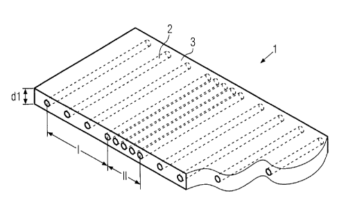
Figure 1A shows a view of an embodiment of a mat 1 for the transport of at
least one object.
The depicted mat 1 possesses a cuboid shape with a thickness dl and comprises
reinforce-
ments 2 that are at least partially enclosed by an elastic material 3. The
reinforcements 2 are
enclosed by the elastic material 3 along their longitudinal direction. On the
front sides, the rein-
forcements 2 end in the area of side surfaces of the mat 1 and are there not
enclosed by the
elastic material 3. It can also be provided, however, that the reinforcements
2 end within the
mat 1 and consequently within the elastic material 3, so that the
reinforcements 2 are also
enclosed by the elastic material 3 on their front sides. This can be
advantageous if the mat 1 is
subject to lateral guidance, for example, during the forward movement on a
roller conveyor,
because then the same and not changing material comes into contact with the
lateral guide.
The reinforcements 2 are aligned parallel to one another and possess a centre-
to-centre dis-
tance apart from one another that can be selected in a ratio to the diameter
of the reinfo-
cements 2 and / or the thickness dl of the mat 1 and / or to the at least one
object that is to be
transported. In the shown embodiment, the mat 1 comprises two areas I, II in
which adjacent
reinforcements 1 possess different centre-to-centre distances. The centre-to-
centre distance is
greater in the first area I than in the second area II.
The centre-to-centre distance between the individual reinforcements 2 can be
selected accord-
ing to the objects to be transported. A larger or smaller centre-to-centre
distance between the
reinforcements 2 can be required, depending on the mass per surface unit that
an object ex-
erts. The stability of the reinforcements 2 can also be correspondingly
influenced by their
thickness or their structure.
Figure 1 B shows a second embodiment of a mat 4 with a thickness d2 for the
transport of at
least one object. In addition to the reinforcements 2, the mat 4 hereby also
comprises ele-
ments 5 that are located in a plane between the reinforcements 2 and the top
surface of the
mat 4. These elements 5 are also at least partially enclosed by the elastic
material 3. These
elements 5 are likewise aligned parallel to one another, whereby the centre-to-
centre distance
between the elements 5 or the size of the elements 5 is selected in such a way
that the dis-
tance between the elements 5 can be less than the distance between the
reinforcements 2. In
the depiction, the elements 5 possess a cuboid structure; other suitable
structures are also
CA 02770102 2012-03-02
possible, however. The elements 5 can comprise the same material as the
reinforcements 2 or
instead also other materials.
As a result of the additional elements 5, the reinforcements 2, the elastic
material 3 and the
additional elements 5 interact in such a way that the mat 4 can be flexed at a
different force in
a plane that runs perpendicular to the longitudinal direction (y-axis) of the
reinforcements 2
and, e.g., parallel to the mat top surface. If the x-y plane of a Cartesian
coordinate system is
set for example by the longitudinal direction (y-axis) of the reinforcements 2
and the z-axis is
aligned perpendicular to the mat top surface in the area of the mat that
comprises the ele-
ments 5, an arc of curvature can be produced in the negative z-direction
(curvature with the
concave side down) with less force than an arc of curvature in the positive z-
direction (curva-
ture with the concave side up) because the elements 5 hinder a compression of
the mat (i.e.,
of the elastic material in this area) above the reinforcements 2. According to
an embodiment,
the mat can possess different flexural stiffness levels during a curvature of
the mat in opposite
directions.
Figure 2A depicts a mat 1 of the first embodiment that is flexed with a first
arc of curvature in
an x-z plane that runs perpendicular to the longitudinal extension of the
reinforcements 2 (y-
axis). Figures 2B and 2C show the view of the mat in a sectional view in the x-
z plane and in a
sectional view in the y-z plane, respectively.
In the x-z plane, a flexing of the mat 1 can result from the elastic material
3 that at least par-
tially encloses the reinforcements 2. No flexing of the mat 1 occurs in the y-
z plane.
Figure 3A depicts a mat 1 of the first embodiment that is flexed with a first
arc of curvature in a
plane that runs perpendicular to the longitudinal extension of the
reinforcements 2 (y-axis).
Figures 3B and 3C show the view of the mat in a sectional view in the x-z
plane and in a sec-
tional view in the y-z plane, respectively.
In the y-z plane, the flexing possibility of the mat 1 is restricted due to
the reinforcements 2
that it comprises, so that only a restricted flexing is possible in a
direction parallel to the longi-
tudinal direction (y-axis) of the reinforcements 2. During flexing of the mat
1 that would lead to
a deformation in the z-direction by more than &zmax, there would result a
plastic deformation of
the reinforcements 2 and consequently the mat 1 would not be in a condition
possible for use
or it would only be in a restricted condition possible for use.
CA 02770102 2012-03-02
11
No flexing of the mat 1 occurs in the x-z plane (Figure 3B).
The properties of the mat 1 that are depicted in Figures 2A to 3C reflect the
desired behaviour
of such a mat 1. In the event of the action of an external force, the mat is
easier to deform in
the x-z plane than in the y-z plane. This can be advantageous for the
transport of objects.
Figure 4 shows a view of a transfer device. A mat 1 of the first embodiment is
moved forwards
on a roller conveyor by means of rollers 61 ... 6n. The rollers 61 ... 6n can,
for example, be
mounted on a lateral limitation 7, whereby this limitation 7 can also continue
to provide lateral
guidance of the mat 1. In order to allow a return of the mat 1, the transfer
station possesses
guidance rollers 81 ... 83 that initiate a deflection of the mat 1 out of the
plane of the roller con-
veyor. By means of the guidance rollers 81 ... 83, an external force can be
exerted on the mat
1, so that the mat 1 can be flexed with an arc of curvature that runs in a
plane perpendicular to
the longitudinal direction (y-axis) of the reinforcements 2. Instead of
guidance rollers 8, other
guidance means, such as motion links or belts, can also be provided. After the
mat 1 has been
flexed out of the plane of the roller conveyor, the mat 1 can be transported
forward by using
additional rollers and consequently, for example, to a location at which the
mat 1 can be used
again for the transport of at least one object.
The guidance rollers 81 ... 83 can possess a diameter that is greater than or
equal to or less
than that of the rollers 6. The length (measured in the axial direction) of
the guidance rollers 81
... 83 is shorter than that of the rollers 6, because these extend across the
conveyor width,
while the guidance rollers 81 ... 83 are provided only on the sides. Fig. 4
depicts only the guid-
ance rollers 81 ... 83 on a back side of the conveyor in Fig. 4. Corresponding
guidance rollers
are also provided on the front side, but these are not depicted here for the
sake of clarity.
The following shows how a transfer of a container from a mat 1 to a conveyor
belt 10 can take
place on the basis of Figures 5A to 5D.
Figures 5A to 5D show how a container 9 can be transported along a roller
conveyor with roll-
ers 61... 6n and a lateral limitation 7 by means of a mat 1. In the figures,
only the lateral limita-
tion 7 is shown that is located in the picture plane behind the mat 1 and the
container 9; the
lateral limitation that is located in the picture plane in front of the mat 1
and the container 9
was left out for the sake of clarity. Due to the rotation of the rollers 61
... 6n, the mat 1 is moved
CA 02770102 2012-03-02
12
forward in the direction of a transport direction and the mat 1 is moved
together with the con-
tainer 9 relative to the roller conveyor (in the depiction, the transport of
the container 9 takes
place from left to right).
While here a mat such as it was described above can be used, it is also
possible to use sim-
pler mats that, although they comprise elastic material, do not comprise any
reinforcements.
The flexural behaviour of the material of such mats is the same in two
different planes, for ex-
ample.
Figure 5A shows how the mat is moved on to the transfer station by means of
the roller con-
veyor by rotating the rollers 61 ... 6, A container 9 located on the top
surface of the mat 1 is
correspondingly moved forwards together with the mat. When the mat 1 reaches
an end of the
roller conveyor, the mat 1 can be moved out of a transport plane by using the
guidance rollers
81 ... 83 that exert an external force on the mat 1.
In the depicted case, the transport plane runs parallel to the longitudinal
extension of the roll-
ers 61...6, or also parallel to the longitudinal extension of the
reinforcements 2 (i.e., perpen-
dicular to the drawing plane) and through the centre plane of the mat 1.
As a result of the force transmission of the guidance rollers 81 ... 83, the
mat 1 can, as depicted
in Figure 5B, be curved away downwards, so that a transfer of the container 9
to a conveyor
belt 10 that can be moved forwards by means of a roller 11 can take place. The
guidance roll-
ers 81 ... 83 are hereby (as depicted in Figure 4) formed in such a way that
they possess a lim-
ited length and do not extend across the entire width of the roller conveyor.
The transport of
the container 9 is consequently not hindered by the guidance rollers 81 ... 83
and the container
9 can therefore be moved to the lateral limitation 7 unhindered between the
guidance rollers 81
... 83, each of which is mounted on opposite sides of the roller conveyor.
Because the mat 1 comprises reinforcements 2 that are aligned perpendicular to
the transport
direction, it is possible, as mentioned above, to transfer a force to the mat
1 by means of these
guidance rollers 81 ... 83 in an edge area of the top surface of the mat 1. A
bulging of the mat 1
in an area between the guidance rollers 81 ... 83 is prevented by the
reinforcements 2. If there
were no reinforcements, a mat, if it consisted of elastic materials, could
bulge because no
force is transferred from above onto the top surface of the mat in the area
between the guid-
ance rollers 81 ... 83.
CA 02770102 2012-03-02
13
As shown in Figures 5A to 5D, the guidance rollers 81 ... 83 are hereby
arranged at successive
positions in the direction of the transport direction, whereby a first
guidance roller 81 acts on
the top surface of the mat 1 and consequently transfers a force while the
entire mat 1 is still
located in the transport plane. A second guidance roller 82 is arranged to the
right of the first
guidance roller 81 and is located below the first guidance roller 81, so that
this second guid-
ance roller 82 exerts a force from above on to the top surface of the mat 1,
as a result of which
the mat 1 is curved downwards away from the transport plane. A third guidance
roller 83 is
arranged to the right of the second guidance roller 82 and is located below
the second guid-
ance roller 82. Consequently, on the top surface of the mat 1 that has already
been curved
downwards a further force can be exerted which further curves the mat 1
downwards.
The mat 1 that has been curved downwards can be transported back, for example,
to a start-
ing point at which mats 1 that are not in use can be stored, by means of
rollers 61 ... 6n in a
plane below the transport plane. The rollers 6 that connect to the guidance
rollers 8 can again
extend across the entire width of the conveyor.
In order to transfer the container on to the conveyer belt 10 after the
descent of the mat 1, a
slide 14 with a movable arm 13 is provided that slides the container 9 from
the mat 1 on to the
conveyor belt 10. It can also be provided that the slide 14 supports the
container 9 in that the
slide 14 follows the container 9 by means of the movable arm 13 during the
forward movement
of the container 9 on the mat 1. In order to bridge a distance that may exist
between the area
of the descending mat 1 and the conveyor belt 10, a support structure 12 can
be provided that,
for example, prevents a container from becoming wedged in this area. In order
for the con-
tainer 9 to be able to pass this support structure 12 without problems, the
slide 14 can now
slide the container 9 in the direction of and on to the conveyor belt 10, in
addition to having its
support function.
The mat 1 and the conveyor belt 10 advantageously have the same speed so that
during a
transfer of the container there is no acceleration or deceleration of the
container 9 which could
lead to an instable position of the container 9. The mat 1 and the conveyor
belt 10 can also,
however, possess different speeds because the slide 14 can give the container
stability during
the transfer if the slide 14 possesses, for example, such a shape and size
that the container 9
can, for example, be supported on a lateral surface.
CA 02770102 2012-03-02
14
After the conclusion of the transfer of the container 9 to the conveyor belt
10 (Figure 5D), i.e.,
the container 9 is then located with its base completely on the conveyor belt
10, the transfer of
the container 9 by means of the slide 14 ends.
It is also possible that the container 9 is transferred to a pallet or another
device (instead of on
to a conveyor belt 10), whereby the pallet (or another device) can be at rest.
The container 9
can likewise be transferred to another roller conveyor or also to another mat
1, 4.
Fig. 6 shows a transfer device for transferring an object on to a mat. The mat
can be an
above-described mat (with reinforcements) or also a simpler mat, meaning one
without rein-
forcements.
The transfer device comprises rollers 20, to 20r, with which a mat can be
guided or moved. At
least some of the rollers can be driven, so that consequently the mat can be
moved. The mat
can be guided between groups of rollers 20, to 20, and 21, to 21m that are
located on opposite
sides of the track of a mat and can act on opposite sides of a mat. In this
way, a mat can be
guided or conveyed in a stable manner, even if the mat is guided in a vertical
position or is
turned (top side down and bottom side up). Rollers on opposite sides of the
track of the mat
can also form roller pairs, of which at least one, preferably both, are driven
in order to convey
the mat. The mat can be clamped between two rollers of a roller pair and be
guided or con-
veyed under the pressure that is produced in this way.
The transfer device comprises an area 27 in which the mat is curved.
Rollers 22, to 22, are furthermore provided that define a transport plane in
which the mat can
be transported in a flat (not curved) position.
A support structure 25 can be provided between a feeding conveyor 23 and the
rollers 20,
21, 22, whereby this support structure 25 bridges the area between the feeding
conveyor
and the rollers.
According to Fig. 6A, a mat is fed below the transport plane. The front area
of the mat is al-
ready curved upwards and moved upwards in the area 27. An object 9 arrives on
the feeding
conveyor 23, whereby this object 9 is to be transferred to a position on the
mat.
CA 02770102 2012-03-02
Fig. 6B shows how the mat has already been further conveyed upwards and turned
in this
process. The front end of the mat is already located in the transport plane
and is flat. The
object 9 is put on to what is then the top side of the mat, for example, by
means of a slide
24. The rear portion of the mat is still curved in the area 27. It arrives in
the transport plane
below the object 9.
Fig. 6C depicts how the mat as a whole has been brought into the transport
plane and now
is transported in a flat position. The transferred object 9 is located on the
mat.
Fig. 6B shows a roller 26 that, for example, can be provided on the edge of
the conveyor
belt. Two such rollers 26 can be provided on the left and right sides of the
track of the mats,
viewed in the conveying direction of the mats, and can help to move the mat
out of the area
27, in which the mat is curved, into the transport plane in a flat position.
The rollers 26
thereby press the mat downwards, so that it comes into the transport plane
flat instead of in
a bunched up position. The rollers 26 thereby act on the top side of the mats.
A plurality of
roller pairs 26 (in each case, a roller of the pair 26 to the right and left)
can be provided
along the track of the mats in order to achieve better guidance of the mats.
The objects 9
can run through between two rollers 26, one of which is provided on the right
and one of
which is provided on the left side of the track of the mats.
Instead of or in addition to a slide 24, the support structure 25 can also be
formed in a tilted manner.
It can also possess rollers itself, on which the object 9 slides downwards due
to gravity.