Note: Descriptions are shown in the official language in which they were submitted.
CA 02770163 2012-02-24
SECONDARY CONTAINMENT SYSTEM USING MODULAR PANELS,'
FIELD OF THE INVENTION
The present invention relates generally to a secondary containment
system using modular panels for connection to one another to form a defined
perimeter around liquid storage tanks or the like, and more particularly the
present
invention relates to modular panels including ground support gussets which are
hinged on an external side thereof.
BACKGROUND
Often with large liquid storage tanks, such as used by petroleum
companies in oil fields, etc., there is a need to provide a secondary
containment wall
around the liquid storage tank to prevent the liquid from being substantially
lost if
failure were to occur to the liquid storage tank. Generally, secondary
containment
walls are constructed using modular sections requiring extensive assembly and
dismantling during setup and removal processes.
US Patent Application Publication No. US2011/0265405 by Ksenych et
al discloses a modular containment system for forming a defined perimeter
around
liquid storage tanks or the like, The containment system generally includes a
plurality
of wall panels and support units associated with each panel in which the
support unit
is comprised of a gusset and anchor pad for supporting the wall panels along a
straight line. A liner is generally secured along an interior of the wall
panels via a
retaining cap. The support units retained on the panels by a bottom hook
structure at
a bottom end and by use of fasteners at the top end. The support units can
therefore
be inadequately secured if the bottom hook structure becomes bent or deformed
after
repeated use. Furthermore, the fasteners of the support units require time
consuming
disassembly and reassembly between uses at different sites as the support
units must
CA 02770163 2012-02-24
2
be removed from the panels for efficient transport between the different
sites.
SUMMARY OF THE INVENTION
According to one aspect of the invention there is provided a modular
containment wall system for use with a barrier member to provide secondary
containment around one or more liquid storage tanks in a storage area, the
wall
system comprising:
a plurality of panel members arranged to be connected in series with
one another to form a perimeter about the storage area, each panel member
comprising:
a main wall portion spanning vertically between a top and a
bottom of the panel member and spanning longitudinally between opposing ends
which are arranged for fastening to the ends of adjacent ones of the panel
members
in the perimeter about the storage area; and
a brace comprising a triangular gusset panel having a first edge
16 which is coupled by a hinge to the main wall portion for relative
pivotal movement
about a hinge axis which extends vertically between the top and bottom edges
of the
panel member between a working position in which the gusset panel is
substantially
perpendicular to the main wall portion and a storage position in which the
gusset
panel is substantially parallel to the main wall portion.
The use of gusset panels which are hinged on an external side of the
panels provides both ready collapsibility for transport and a strong mounting
connection which is readily erected when placed in a working position on site
within a
containment wall system.
Preferably the hinge spans a full height of the first edge of the gusset
panel.
CA 02770163 2012-02-24
3
Preferably the hinge is coupled to the main wall portion at an
intermediate location spaced inwardly from both ends of the main wall portion
so as to
be substantially centered between the opposing ends.
Preferably the gusset panel includes a second edge which is
perpendicular to the first edge so as to be substantially in a common plane
with a
bottom of the main wall portion.
Preferably a locking member is arranged to be coupled to the brace so
as to selectively retain the brace in the working position.
Preferably the locking member is movable between a locked position in
which the brace is retained in the working position and a released position in
which
the brace is freely pivotal from the working position to the storage position
and
wherein there is provided a spring biasing the locking member into the locked
position.
The locking member may be slidably mounted on the main wall portion
for substantially vertical movement between the locked position in which the
locking
member engages the brace and the released position in which the locking member
is
disengaged from the brace.
Preferably the brace includes a foot panel mounted along a second
edge of the gusset panel so as to be substantially perpendicular to the main
wall
portion adjacent the bottom end of the panel member in which the foot panel is
pivotal
with the gusset panel relative to the main wall portion between the working
position
and the storage position.
Preferably the foot panel is arranged to be received below a bottom of
the main wall portion in the storage position.
Preferably the locking member is slidably mounted on the main wall
CA 02770163 2012-02-24
4
portion for engaging the foot panel of the brace in the locked position.
When the gusset panel includes opposing first and second sides and the
hinge is coupled to the first side, preferably the foot panel is offset
relative to the
gusset panel in a longitudinal direction of the main wall portion in the
working position
such that the foot panel projects longitudinally outward from the first side
of the gusset
panel greater than the second side of the gusset panel.
The panel members may further comprise a pair of mounting flanges
respectively supported on the opposing ends of the main wall portion, in which
the
mounting flanges span between the top and bottom of the panel member
perpendicular to the main wall portion and in which the mounting flanges
include
mounting apertures. The mounting apertures receive threaded fasteners
therethrough which are mounted through the mounting apertures of the mounting
flanges of adjacent panel members of like configuration.
One embodiment of the invention will now be described in conjunction
with the accompanying drawings in which:
BRIEF DESCRIPTION OF THE DRAWINGS
Figure 1 is a perspective view of one of the panel members of the
modular containment wall system;
Figure 2 is a perspective view of the hinge coupling the brace to the
main wall portion of the panel member of Figure 1;
Figure 3 is a top plan view of one of the panel member of Figure 1;
Figure 4 is a front elevational view of the brace coupled to the panel
member of Figure 1;
Figure 5 is a front elevational view of the connected ends of two
adjacent panel members of an assembled modular containment wall system;
CA 02770163 2012-02-24
Figure 6 is a side elevational view of the locking member in the locked
position; and
Figure 7 is a side elevational view of the locking member in the released
position.
5 In the
drawings like characters of reference indicate corresponding parts
in the different figures.
DETAILED DESCRIPTION
Referring to the accompanying figures, there is illustrated a modular
panel member generally indicated by reference numeral 10. The panel member 10
is
suited for use in forming a containment wall system for secondary containment
about
one or more liquid storage tanks within a storage area.
The panel members 10 are arranged to be connected end to end in
series with one another to form a perimeter wall of the wall system about the
storage
area. The secondary containment system further includes a barrier member (not
shown) in the form of a flexible and liquid impervious sheet which is joined
to the top
edge of the perimeter wall to fully span the storage area.
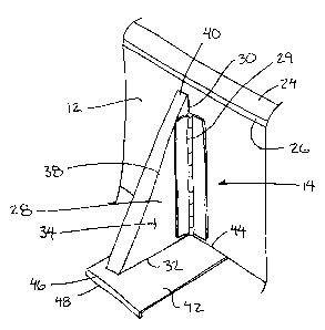
Each panel member 10 includes a main wall portion 12 and a brace 14
which is pivotally coupled to an exterior side of the main wall portion for
pivotal
movement between a working position protruding externally outward from the
wall
portion and a storage position extending generally alongside the wall portion.
The main wall portion 12 is a flat rectangular rigid sheet of metal
spanning vertically a full height between top and bottom ends of the panel
member.
The main wall portion is also elongate in a longitudinal direction between two
opposed
ends 16.
A mounting flange 18 is formed integrally at each of the ends 16 to also
CA 02770163 2012-02-24
6
span the full height while being oriented perpendicularly to the longitudinal
direction to
project externally outward from the exterior side of the main wall portion.
Slotted
apertures 20 are formed in each mounting flange at vertically spaced positions
for
aligning with the mounting apertures of corresponding mounting flanges of
adjacent
panel members when connected in series to form the perimeter wall. Bolts 22
are
fastened through each cooperating pair of apertures between two adjacent
panels for
secure fastening at vertically spaced apart positions at each end to end
connection of
adjacent panels.
Each panel member further includes a cap portion 24 integrally formed
along the top edge of the main wall portion to project horizontally and
externally
outward from the main wall portion to a depending edge flange 26. The cap
portion
thus forms a generally inverted U-shape with the main wall portion.
The interior side of each panel member remains flat and smooth to
permit the barrier member to be readily draped over the inner surface and
secured at
its edge overtop of the cap portion 24. A cap member (not shown) may
additionally
be provided for retaining the barrier member draped over the cap portion.
Each brace 14 is coupled intermediately at a central location between
opposing ends of the main wall portion of each panel member so as to be spaced
inwardly from both ends.
Each brace 14 includes a gusset panel 28 which is generally triangular
in shape. The gusset panel 28 includes a first edge 30 which is joined by the
hinge
29 substantially along the full height thereof to the exterior side of the
panel member
to define a vertical pivot axis of the pivotal movement of the brace relative
to the main
wall portion. The pivot axis is oriented to extend vertically between top and
bottom
ends of the panel parallel to the mounting flanges at opposing ends of the
main wall
CA 02770163 2012-02-24
7
portion.
Each gusset panel 28 further includes a second edge 32 along the
bottom side which is in alignment with the bottom of the main wall portion so
as to lie
in a substantially common horizontal plane therewith. The second edge 32 is
thus
oriented substantially perpendicularly to the first edge.
The gusset panel 28 also includes a first side surface 34 and an
opposing second side surface 36 in which the hinge couples between the first
side
surface and the exterior side of the main wall portion. The gusset panel 28 is
thus
pivotal between the working position in which the side surfaces of the panel
are
oriented perpendicularly to the main wall portion and the storage position in
which the
side surfaces are substantially parallel to the main wall portion. By coupling
the hinge
29 to the first side surface, the first side surface lays substantially flat
against the
exterior side of the main wall portion in the storage position while the
opposing
second side surface faces outwardly.
The gusset panel 28 further includes a third edge 38 which extends at a
downward and outward incline from the top of the first edge to the outer end
of the
second edge in the working position. A stiffener flange 40 is integrally
formed along
the third edge of the gusset panel to project outward from the second side
surface 36
substantially perpendicularly to the side surfaces.
The brace further includes a foot panel 42 in the form of a rigid
rectangular sheet fixed to the second edge 32 at the bottom of the gusset
panel so as
to be pivotal therewith relative to the main wall portion. The foot panel is
fixed
perpendicularly to the gusset panel so as to lie in a substantially horizontal
plane
which is also perpendicular to the main wall portion and the vertical pivot
axis. The
foot panel thus remains perpendicular to the main wall portion throughout the
pivoting
CA 02770163 2012-02-24
8
movement between the working and storage positions.
In the working position an inner edge 44 of the rectangular panel is
parallel and alongside the bottom edge of the main wall portion while the
outer edge
46 is spaced externally outward from the main wall portion beyond the end of
the
second edge of the gusset panel 28. A depending flange 48 is formed at the
outer
edge 46 of the foot panel to bite downward into the ground in the working
position.
Furthermore in the working position the foot panel 42 is offset in the
longitudinal direction of the main wall portion in relation to the gusset
panel 28 such
that the foot panel projects in the longitudinal direction of the main wall
portion a
greater distance from the first side surface 34 than in the opposing direction
from the
second side surface 36. In this arrangement in the storage position, the
larger offset
from the first side of the gusset panel locating the hinge thereon projects
below the
bottom of the main wall portion forming a compact storage position even when
the
foot panel remains fixed perpendicularly to the gusset panel and the gusset
panel is
hinged on the main wall portion during storage. The foot panel is slidable
below the
bottom edge of the main wall portion as the brace is pivoted between the
working and
storage positions.
A locking member 50 is provided in the form of a vertical pin mounted on
the exterior surface of the main wall portion for vertical sliding movement
between a
locked position and a released position. The locking member is supported on
the
main wall portion adjacent the bottom end thereof for selective engagement
with the
foot panel 42 of the brace adjacent to the second side surface of the gusset
panel.
The locking member is vertically slidable downward into the locked position
from the
released position such that in the locked position the bottom end of the
locking
member extends below the bottom edge of the main wall portion for cooperation
with
CA 02770163 2012-02-24
9
a locking aperture 52 in the foot panel 42 when the foot panel is in the
working
position. In this instance the locking member retains the brace in the working
position
and prevents pivotal movement into the storage position.
Two mounting flanges 54 are horizontally oriented and supported in
vertical alignment with one another so as to be vertically spaced apart on the
exterior
surface of the main wall portion. Apertures 56 in the two mounting flanges 54
receive
the locking member extending vertically slidably therethrough. A spring 58 is
mounted between the uppermost one of the mounting flanges 54 and a protrusion
60
located at an intermediate location along the body of the locking member such
that
compression of the spring biases the protrusion 60 and the locking member 50
upon
which is formed downwardly into the locked position.
Sliding the locking member upwardly from the locked position against
the force of the spring 58 by compressing the spring causes the bottom end of
the
locking member to be raised above the bottom of the main wall portion and thus
be
disengaged from the foot panel. Accordingly in the released position, the
brace is
freely pivotal from the working position to the storage position while the
locking
member 50 remains retained on the exterior side of the main wall portion.
Since various modifications can be made in my invention as herein
above described, and many apparently widely different embodiments of same made
within the spirit and scope of the claims without department from such spirit
and
scope, it is intended that all matter contained in the accompanying
specification shall
be interpreted as illustrative only and not in a limiting sense.