Language selection

Search

Patent 2770273 Summary

Third-party information liability

Some of the information on this Web page has been provided by external sources. The Government of Canada is not responsible for the accuracy, reliability or currency of the information supplied by external sources. Users wishing to rely upon this information should consult directly with the source of the information. Content provided by external sources is not subject to official languages, privacy and accessibility requirements.

Claims and Abstract availability

Any discrepancies in the text and image of the Claims and Abstract are due to differing posting times. Text of the Claims and Abstract are posted:

  • At the time the application is open to public inspection;
  • At the time of issue of the patent (grant).
(12) Patent Application: (11) CA 2770273
(54) English Title: M - VC/S CAM VARIABLE CYCLE/VARIABLE STROKE CAM INTERNAL COMBUSTION ENGINE
(54) French Title: MOTEUR A COMBUSTION INTERNE A CAME A COURSE VARIABLE ET CYCLE VARIABLE (M - VC/S CAM)
Status: Deemed Abandoned and Beyond the Period of Reinstatement - Pending Response to Notice of Disregarded Communication
Bibliographic Data
Abstracts

English Abstract


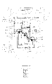
A variable cycle / variable stroke profiled circular cam attached to a drive
shaft motivated by
multiple pistons reciprocating within annularly displaced stationary cylinders
. The engine is
designed to require a minimum of engine components to operate thus achieving a
reduction in
manufacturing time, cost, and energy requirements. Due to the low engine
parts, operating
efficiencies will result in lower fuel consumption and lower exhaust
temperatures compared to
existing engines of equivalent horsepower. Of importance is the function of
the variable
cycle/stroke feature profiled on the operating cam attached to the main drive
shaft. The
profiled cam ensures that the intake and compression strokes operate at one
half the piston
travel distance as that of the power and exhaust strokes. The pistons operate
independently
thus allowing for the profiled cam to be configured for a variable four
cycle/stroke operation.
This engine design can use many existing modified components in the
manufacturing process
thus reducing the need for re-tooling requirements. The engine can be a direct
replacement for
all existing engine applications including automotive, aviation, marine and
power tools. The
engine design is capable of expanding from 1 cylinder to a multiple of
cylinders depending on
operational requirements.


Claims

Note: Claims are shown in the official language in which they were submitted.


CLAIMS
The embodiments of the invention in which an exclusive property or privilege
is claimed are
defined as follows:
1. An internal combustion engine designed to operate consisting of a variable
cycle and a
variable stroke profiled cam to power an output drive shaft, it's rotation
motivated by multiple
pistons operating in stationary annularly distributed cylinders.
2. A circular variable cycle/variable stroke profiled operating cam
3. Pistons with wristpins powering and rolling on a variable cycle/variable
stroke profiled
operating cam attached to a power output drive shaft.
4. Secondary rollers and operating mechanism attached to piston wrist pin and
in contact with
the underside of the operating cam lip .
5. A circular rotating manifold inside a cylinder manifold cover containing
both intake and
exhaust passages to provide the necessary intake and exhaust functions and
attached to the
power output drive shaft.
6. Integrated power output shaft, manifold connecting rod and manifold
rotating structure.
7. Grooved cylinder liners.
3

Description

Note: Descriptions are shown in the official language in which they were submitted.


CA 02770273 2012-02-28
, t
M - VC/S CAM
Variable Cycle / Variable Stroke
Cam
Internal Combustion Engine

CA 02770273 2012-02-28
a
Description.
The engine's main design feature is the variable cycle and variable stroke (1
)Figure 1 and the
cycle profiled operating cam (2) Figure 2 attached to a drive shaft (7). The
engine design is
simpler in construction and operation than existing similar designs.
The variable cycle/stroke profiled cam is designed as a new approach to
internal combustion
engine technology so that the intake and compression strokes are at least half
the length of the
power and exhaust strokes and the cam's circular variable cycle feature is
designed so that the
intake cycle Figure 1 (3) is 60 degrees, compression cycle (4) is 80 degrees,
the power cycle (5)
is 130 degrees, the exhaust cycle (6) is 90 degrees. The cycle spacing ensures
that in a 4 or
more cylinder configuration, there will always be two or more pistons on the
power
cycle/stroke. The power cycle/stroke allows the pistons to utilize the
combustion force for the
full linear length of the power cycle/stroke.
A counter clockwise or clockwise rotating power drive shaft (7) Figure 4 with
specially
cycle/stroke profiled operating cam (2) with an intake/exhaust manifold (8)
connected directly
to the drive shaft (7) via connecting shaft (9) secured with an end plate (29)
and with provision
for strategically located thrust bearings (28) strategicaly installed along
the drive shaft and the
engine housing (25). Main variable cycle/variable stroke profiled cam (2) is
attached to the
drive shaft either directly or machined to allow position adjustments and
attached with bolts.
The cam is circular with the top portion wider (10) than the cam structure to
allow piston wrist
pins (12) to roll on top of the cam profile and rollers (13) to roll on the
bottom of the cam lip
(11).
Intake/exhaust steel plate (15) is also adjustable and directly attached to
the intake/exhaust
manifold (8) via a connecting rod (9) to the drive shaft (7). The
intake/exhaust manifold plate is
set to rotate sealed and flush with the top of the cylinder head (31). The
plate has compatible
strategically positioned intake opening (16) Figure 7 and exhaust opening (17)
to match those in
the cylinders' intake (18) and exhaust (19) requirement for intake and exhaust
functions and
timed to perform their functions at the appropriate cycle.
1

CA 02770273 2012-02-28
e
The manifold (8) is grooved and sealed so that air/fuel from the carburetor or
fuel injector(22)
opening is continually available to inject into each cylinder intake port as
the plate opening (16)
passes over the cylinder head cover (33) opening (18) thus completing the
intake cycle. Fuel can
be injected directly into the cylinders.
The exhaust manifold (20) is a circular groove in the cylinder head cover(33)
and the manifold
(8) allowing continuous exhaust flow access to the exhaust manifold and also
sealed from the
air/fuel groove and is designed to accept the exhaust from the cylinders when
the ports overlap
and direct to the exhaust manifold exit (21). The intake groove (22) Figure 7
is set on the inner
portion of the manifold (8) and the exhaust groove (20) on the outer portion
of the manifold.
The pistons (23) Figure 5 operating inside cylinders (24) figures 6 and 7 are
equally spaced in a
circle (4 cylinders shown) with the cycle/stroke cam rotating through the
middle of the
cylinders. The cam's rotation is motivated by the powered pistons via wrist
pins (12) Figure 5
rolling on top of the profiled cam and rollers (13) also attached to the
pistons and roll on the
underside of the cam lip attached to the wrist pin with a movable plate to
allow the bottom
roller flexibility to remain attached to the cam lip. This eliminates the
requirement for
connecting rods between the pistons and the cam. The stationary cylinder walls
(24) Figure 6
have preset openings (30) to allow unobstructed cam rotation. An aluminum
cylinder head (31)
Figure 4 provides an interface between the cylinders and the intake 22 and
exhaust groove (20)
and steel plate (15) on the manifold (8) and the cylinder manifold cover (33).
ignition is
provided utilizing electronic or standard spark plugs for each cylinder.
The engine casing (25) is indicated for simplicity and can be air or liquid
cooled and contains
provisions for engine oil lubrication and ancillary engine accessory
equipment. Long mounting
bolts (26) Figure 7 secure top and bottom sections of engine and short
mounting bolts (27)
secure the top and the same bolts secure the bottom sections. This alternating
bolt spacing, ie;
26, 27, 26 etc; around the engine provide for the necessary engine security.
Exhaust gases
exiting (21) Figure 4 will be at a reduced temperature due to the length of
the power cycle/
stroke (5) Figure 1. The engine is mounted to the end product at 4 engine
mounting locations
(32) Figure 7.
2

CA 02770273 2012-02-28
Drawings
Sheet 1: Figure 1 - cycle/stroke profile
Figure 2 - cam/power shaft diagram
Figure 3 - top view of cam
Sheet 2: Figure 4 - side view of engine with selected components outlined
Sheet 3: Figure 5 - piston cam interface
Sheet 4: Figure 6- cylinder liner location and relationship to cam
Sheet 5: Figure 7 - top view of cam/piston/wristpin interface
Sheet 6: Figure 8 - top view of manifold with intake/exhaust ports and
openings
Sheet 7: Figure 9 - exploded view of cylinder head/plate/manifold/cylinder
manifold cover
Sheet 8: Figure 10- cylinder head
Sheet 9: Figure 11 - manifold steel plate with intake/exhaust openings
Sheet 10: Figure 12 - manifold
Sheet 11: Figure 13 - cylinder manifold cover
4

Representative Drawing
A single figure which represents the drawing illustrating the invention.
Administrative Status

2024-08-01:As part of the Next Generation Patents (NGP) transition, the Canadian Patents Database (CPD) now contains a more detailed Event History, which replicates the Event Log of our new back-office solution.

Please note that "Inactive:" events refers to events no longer in use in our new back-office solution.

For a clearer understanding of the status of the application/patent presented on this page, the site Disclaimer , as well as the definitions for Patent , Event History , Maintenance Fee  and Payment History  should be consulted.

Event History

Description Date
Application Not Reinstated by Deadline 2016-03-02
Time Limit for Reversal Expired 2016-03-02
Deemed Abandoned - Failure to Respond to Maintenance Fee Notice 2015-03-02
Maintenance Request Received 2014-02-28
Application Published (Open to Public Inspection) 2013-08-28
Inactive: Cover page published 2013-08-27
Inactive: IPC assigned 2012-04-11
Inactive: First IPC assigned 2012-04-11
Inactive: Correspondence - PCT 2012-03-27
Inactive: IPC assigned 2012-03-23
Inactive: Filing certificate - No RFE (English) 2012-03-16
Inactive: Office letter 2012-03-16
Application Received - Regular National 2012-03-16
Inactive: Office letter 2012-03-16
Small Entity Declaration Determined Compliant 2012-02-28

Abandonment History

Abandonment Date Reason Reinstatement Date
2015-03-02

Maintenance Fee

The last payment was received on 2014-02-28

Note : If the full payment has not been received on or before the date indicated, a further fee may be required which may be one of the following

  • the reinstatement fee;
  • the late payment fee; or
  • additional fee to reverse deemed expiry.

Patent fees are adjusted on the 1st of January every year. The amounts above are the current amounts if received by December 31 of the current year.
Please refer to the CIPO Patent Fees web page to see all current fee amounts.

Fee History

Fee Type Anniversary Year Due Date Paid Date
Application fee - small 2012-02-28
MF (application, 2nd anniv.) - small 02 2014-02-28 2014-02-28
Owners on Record

Note: Records showing the ownership history in alphabetical order.

Current Owners on Record
ANDRE JOHN MEUSE
Past Owners on Record
None
Past Owners that do not appear in the "Owners on Record" listing will appear in other documentation within the application.
Documents

To view selected files, please enter reCAPTCHA code :


To view images, click a link in the Document Description column. To download the documents, select one or more checkboxes in the first column and then click the "Download Selected in PDF format (Zip Archive)" or the "Download Selected as Single PDF" button.

List of published and non-published patent-specific documents on the CPD .

If you have any difficulty accessing content, you can call the Client Service Centre at 1-866-997-1936 or send them an e-mail at CIPO Client Service Centre.


Document
Description 
Date
(yyyy-mm-dd) 
Number of pages   Size of Image (KB) 
Claims 2012-02-27 1 23
Description 2012-02-27 4 119
Abstract 2012-02-27 1 31
Drawings 2012-02-27 11 217
Representative drawing 2012-04-26 1 10
Filing Certificate (English) 2012-03-15 1 156
Notice: Maintenance Fee Reminder 2013-12-01 1 120
Notice: Maintenance Fee Reminder 2014-11-30 1 120
Courtesy - Abandonment Letter (Maintenance Fee) 2015-04-26 1 171
Second Notice: Maintenance Fee Reminder 2015-08-30 1 119
Notice: Maintenance Fee Reminder 2015-11-30 1 128
Correspondence 2012-03-15 1 27
Correspondence 2012-03-15 1 21
Correspondence 2012-03-26 1 20
Fees 2014-02-27 2 63