Sélection de la langue

Search

Sommaire du brevet 2770273 

Énoncé de désistement de responsabilité concernant l'information provenant de tiers

Une partie des informations de ce site Web a été fournie par des sources externes. Le gouvernement du Canada n'assume aucune responsabilité concernant la précision, l'actualité ou la fiabilité des informations fournies par les sources externes. Les utilisateurs qui désirent employer cette information devraient consulter directement la source des informations. Le contenu fourni par les sources externes n'est pas assujetti aux exigences sur les langues officielles, la protection des renseignements personnels et l'accessibilité.

Disponibilité de l'Abrégé et des Revendications

L'apparition de différences dans le texte et l'image des Revendications et de l'Abrégé dépend du moment auquel le document est publié. Les textes des Revendications et de l'Abrégé sont affichés :

  • lorsque la demande peut être examinée par le public;
  • lorsque le brevet est émis (délivrance).
(12) Demande de brevet: (11) CA 2770273
(54) Titre français: MOTEUR A COMBUSTION INTERNE A CAME A COURSE VARIABLE ET CYCLE VARIABLE (M - VC/S CAM)
(54) Titre anglais: M - VC/S CAM VARIABLE CYCLE/VARIABLE STROKE CAM INTERNAL COMBUSTION ENGINE
Statut: Réputée abandonnée et au-delà du délai pour le rétablissement - en attente de la réponse à l’avis de communication rejetée
Données bibliographiques
Abrégés

Abrégé anglais


A variable cycle / variable stroke profiled circular cam attached to a drive
shaft motivated by
multiple pistons reciprocating within annularly displaced stationary cylinders
. The engine is
designed to require a minimum of engine components to operate thus achieving a
reduction in
manufacturing time, cost, and energy requirements. Due to the low engine
parts, operating
efficiencies will result in lower fuel consumption and lower exhaust
temperatures compared to
existing engines of equivalent horsepower. Of importance is the function of
the variable
cycle/stroke feature profiled on the operating cam attached to the main drive
shaft. The
profiled cam ensures that the intake and compression strokes operate at one
half the piston
travel distance as that of the power and exhaust strokes. The pistons operate
independently
thus allowing for the profiled cam to be configured for a variable four
cycle/stroke operation.
This engine design can use many existing modified components in the
manufacturing process
thus reducing the need for re-tooling requirements. The engine can be a direct
replacement for
all existing engine applications including automotive, aviation, marine and
power tools. The
engine design is capable of expanding from 1 cylinder to a multiple of
cylinders depending on
operational requirements.

Revendications

Note : Les revendications sont présentées dans la langue officielle dans laquelle elles ont été soumises.


CLAIMS
The embodiments of the invention in which an exclusive property or privilege
is claimed are
defined as follows:
1. An internal combustion engine designed to operate consisting of a variable
cycle and a
variable stroke profiled cam to power an output drive shaft, it's rotation
motivated by multiple
pistons operating in stationary annularly distributed cylinders.
2. A circular variable cycle/variable stroke profiled operating cam
3. Pistons with wristpins powering and rolling on a variable cycle/variable
stroke profiled
operating cam attached to a power output drive shaft.
4. Secondary rollers and operating mechanism attached to piston wrist pin and
in contact with
the underside of the operating cam lip .
5. A circular rotating manifold inside a cylinder manifold cover containing
both intake and
exhaust passages to provide the necessary intake and exhaust functions and
attached to the
power output drive shaft.
6. Integrated power output shaft, manifold connecting rod and manifold
rotating structure.
7. Grooved cylinder liners.
3

Description

Note : Les descriptions sont présentées dans la langue officielle dans laquelle elles ont été soumises.

CA 02770273 2012-02-28
, t
M - VC/S CAM
Variable Cycle / Variable Stroke
Cam
Internal Combustion Engine

CA 02770273 2012-02-28
a
Description.
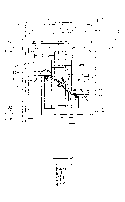
The engine's main design feature is the variable cycle and variable stroke (1
)Figure 1 and the
cycle profiled operating cam (2) Figure 2 attached to a drive shaft (7). The
engine design is
simpler in construction and operation than existing similar designs.
The variable cycle/stroke profiled cam is designed as a new approach to
internal combustion
engine technology so that the intake and compression strokes are at least half
the length of the
power and exhaust strokes and the cam's circular variable cycle feature is
designed so that the
intake cycle Figure 1 (3) is 60 degrees, compression cycle (4) is 80 degrees,
the power cycle (5)
is 130 degrees, the exhaust cycle (6) is 90 degrees. The cycle spacing ensures
that in a 4 or
more cylinder configuration, there will always be two or more pistons on the
power
cycle/stroke. The power cycle/stroke allows the pistons to utilize the
combustion force for the
full linear length of the power cycle/stroke.
A counter clockwise or clockwise rotating power drive shaft (7) Figure 4 with
specially
cycle/stroke profiled operating cam (2) with an intake/exhaust manifold (8)
connected directly
to the drive shaft (7) via connecting shaft (9) secured with an end plate (29)
and with provision
for strategically located thrust bearings (28) strategicaly installed along
the drive shaft and the
engine housing (25). Main variable cycle/variable stroke profiled cam (2) is
attached to the
drive shaft either directly or machined to allow position adjustments and
attached with bolts.
The cam is circular with the top portion wider (10) than the cam structure to
allow piston wrist
pins (12) to roll on top of the cam profile and rollers (13) to roll on the
bottom of the cam lip
(11).
Intake/exhaust steel plate (15) is also adjustable and directly attached to
the intake/exhaust
manifold (8) via a connecting rod (9) to the drive shaft (7). The
intake/exhaust manifold plate is
set to rotate sealed and flush with the top of the cylinder head (31). The
plate has compatible
strategically positioned intake opening (16) Figure 7 and exhaust opening (17)
to match those in
the cylinders' intake (18) and exhaust (19) requirement for intake and exhaust
functions and
timed to perform their functions at the appropriate cycle.
1

CA 02770273 2012-02-28
e
The manifold (8) is grooved and sealed so that air/fuel from the carburetor or
fuel injector(22)
opening is continually available to inject into each cylinder intake port as
the plate opening (16)
passes over the cylinder head cover (33) opening (18) thus completing the
intake cycle. Fuel can
be injected directly into the cylinders.
The exhaust manifold (20) is a circular groove in the cylinder head cover(33)
and the manifold
(8) allowing continuous exhaust flow access to the exhaust manifold and also
sealed from the
air/fuel groove and is designed to accept the exhaust from the cylinders when
the ports overlap
and direct to the exhaust manifold exit (21). The intake groove (22) Figure 7
is set on the inner
portion of the manifold (8) and the exhaust groove (20) on the outer portion
of the manifold.
The pistons (23) Figure 5 operating inside cylinders (24) figures 6 and 7 are
equally spaced in a
circle (4 cylinders shown) with the cycle/stroke cam rotating through the
middle of the
cylinders. The cam's rotation is motivated by the powered pistons via wrist
pins (12) Figure 5
rolling on top of the profiled cam and rollers (13) also attached to the
pistons and roll on the
underside of the cam lip attached to the wrist pin with a movable plate to
allow the bottom
roller flexibility to remain attached to the cam lip. This eliminates the
requirement for
connecting rods between the pistons and the cam. The stationary cylinder walls
(24) Figure 6
have preset openings (30) to allow unobstructed cam rotation. An aluminum
cylinder head (31)
Figure 4 provides an interface between the cylinders and the intake 22 and
exhaust groove (20)
and steel plate (15) on the manifold (8) and the cylinder manifold cover (33).
ignition is
provided utilizing electronic or standard spark plugs for each cylinder.
The engine casing (25) is indicated for simplicity and can be air or liquid
cooled and contains
provisions for engine oil lubrication and ancillary engine accessory
equipment. Long mounting
bolts (26) Figure 7 secure top and bottom sections of engine and short
mounting bolts (27)
secure the top and the same bolts secure the bottom sections. This alternating
bolt spacing, ie;
26, 27, 26 etc; around the engine provide for the necessary engine security.
Exhaust gases
exiting (21) Figure 4 will be at a reduced temperature due to the length of
the power cycle/
stroke (5) Figure 1. The engine is mounted to the end product at 4 engine
mounting locations
(32) Figure 7.
2

CA 02770273 2012-02-28
Drawings
Sheet 1: Figure 1 - cycle/stroke profile
Figure 2 - cam/power shaft diagram
Figure 3 - top view of cam
Sheet 2: Figure 4 - side view of engine with selected components outlined
Sheet 3: Figure 5 - piston cam interface
Sheet 4: Figure 6- cylinder liner location and relationship to cam
Sheet 5: Figure 7 - top view of cam/piston/wristpin interface
Sheet 6: Figure 8 - top view of manifold with intake/exhaust ports and
openings
Sheet 7: Figure 9 - exploded view of cylinder head/plate/manifold/cylinder
manifold cover
Sheet 8: Figure 10- cylinder head
Sheet 9: Figure 11 - manifold steel plate with intake/exhaust openings
Sheet 10: Figure 12 - manifold
Sheet 11: Figure 13 - cylinder manifold cover
4

Dessin représentatif
Une figure unique qui représente un dessin illustrant l'invention.
États administratifs

2024-08-01 : Dans le cadre de la transition vers les Brevets de nouvelle génération (BNG), la base de données sur les brevets canadiens (BDBC) contient désormais un Historique d'événement plus détaillé, qui reproduit le Journal des événements de notre nouvelle solution interne.

Veuillez noter que les événements débutant par « Inactive : » se réfèrent à des événements qui ne sont plus utilisés dans notre nouvelle solution interne.

Pour une meilleure compréhension de l'état de la demande ou brevet qui figure sur cette page, la rubrique Mise en garde , et les descriptions de Brevet , Historique d'événement , Taxes périodiques et Historique des paiements devraient être consultées.

Historique d'événement

Description Date
Demande non rétablie avant l'échéance 2016-03-02
Le délai pour l'annulation est expiré 2016-03-02
Réputée abandonnée - omission de répondre à un avis sur les taxes pour le maintien en état 2015-03-02
Requête visant le maintien en état reçue 2014-02-28
Demande publiée (accessible au public) 2013-08-28
Inactive : Page couverture publiée 2013-08-27
Inactive : CIB attribuée 2012-04-11
Inactive : CIB en 1re position 2012-04-11
Inactive : Correspondance - PCT 2012-03-27
Inactive : CIB attribuée 2012-03-23
Inactive : Certificat de dépôt - Sans RE (Anglais) 2012-03-16
Inactive : Lettre officielle 2012-03-16
Demande reçue - nationale ordinaire 2012-03-16
Inactive : Lettre officielle 2012-03-16
Déclaration du statut de petite entité jugée conforme 2012-02-28

Historique d'abandonnement

Date d'abandonnement Raison Date de rétablissement
2015-03-02

Taxes périodiques

Le dernier paiement a été reçu le 2014-02-28

Avis : Si le paiement en totalité n'a pas été reçu au plus tard à la date indiquée, une taxe supplémentaire peut être imposée, soit une des taxes suivantes :

  • taxe de rétablissement ;
  • taxe pour paiement en souffrance ; ou
  • taxe additionnelle pour le renversement d'une péremption réputée.

Les taxes sur les brevets sont ajustées au 1er janvier de chaque année. Les montants ci-dessus sont les montants actuels s'ils sont reçus au plus tard le 31 décembre de l'année en cours.
Veuillez vous référer à la page web des taxes sur les brevets de l'OPIC pour voir tous les montants actuels des taxes.

Historique des taxes

Type de taxes Anniversaire Échéance Date payée
Taxe pour le dépôt - petite 2012-02-28
TM (demande, 2e anniv.) - petite 02 2014-02-28 2014-02-28
Titulaires au dossier

Les titulaires actuels et antérieures au dossier sont affichés en ordre alphabétique.

Titulaires actuels au dossier
ANDRE JOHN MEUSE
Titulaires antérieures au dossier
S.O.
Les propriétaires antérieurs qui ne figurent pas dans la liste des « Propriétaires au dossier » apparaîtront dans d'autres documents au dossier.
Documents

Pour visionner les fichiers sélectionnés, entrer le code reCAPTCHA :


Pour visualiser une image, cliquer sur un lien dans la colonne description du document. Pour télécharger l'image (les images), cliquer l'une ou plusieurs cases à cocher dans la première colonne et ensuite cliquer sur le bouton "Télécharger sélection en format PDF (archive Zip)" ou le bouton "Télécharger sélection (en un fichier PDF fusionné)".

Liste des documents de brevet publiés et non publiés sur la BDBC .

Si vous avez des difficultés à accéder au contenu, veuillez communiquer avec le Centre de services à la clientèle au 1-866-997-1936, ou envoyer un courriel au Centre de service à la clientèle de l'OPIC.


Description du
Document 
Date
(aaaa-mm-jj) 
Nombre de pages   Taille de l'image (Ko) 
Revendications 2012-02-27 1 23
Description 2012-02-27 4 119
Abrégé 2012-02-27 1 31
Dessins 2012-02-27 11 217
Dessin représentatif 2012-04-26 1 10
Certificat de dépôt (anglais) 2012-03-15 1 156
Avis de rappel: Taxes de maintien 2013-12-01 1 120
Avis de rappel: Taxes de maintien 2014-11-30 1 120
Courtoisie - Lettre d'abandon (taxe de maintien en état) 2015-04-26 1 171
Deuxième avis de rappel: taxes de maintien 2015-08-30 1 119
Avis de rappel: Taxes de maintien 2015-11-30 1 128
Correspondance 2012-03-15 1 27
Correspondance 2012-03-15 1 21
Correspondance 2012-03-26 1 20
Taxes 2014-02-27 2 63