Note: Descriptions are shown in the official language in which they were submitted.
CA 02770416 2017-02-23
Reciprocating pump drive apparatus for operating a downhole pump via a rod
string
FIELD OF THE INVENTION
The invention relates generally to a mechanism transforming rotary
motion to vertical motion, and more particularly to an apparatus producing
reciprocating pump motion to assist production of fluids from a well.
BACKGROUND OF THE INVENTION
Production of fluids from a well is often assisted or achieved by
operation of a downhole pump that forces fluids up toward the surface.
Reciprocal
drive downhole pumps are operated via a string of rods (sucker rods) that
depend
down into the well from the surface, where the string is reciprocated up and
down
along the axis of the wellbore by above-surface drive equipment. The most
common
conventional downhole reciprocal pump drive equipment configuration is the
walking
beam pump jack, which is often installed atop a concrete pad and may be
further
supported by piles, thus requiring significant preparation and resulting in
notable
ground disturbance.
Other prior art alternatives include hydraulic pump jacks that employ
hydraulic cylinders bolted onto the wellhead to perform the required
reciprocation of
the pump rod string. However, shortcomings of such configurations may include
lack of a smooth transition to the rod string between the up and down strokes,
leaking fluids, and the potential of the hydraulic cylinders to rust because
of
oxidization and exposure to the elements.
CA 02770416 2017-02-23
2
Accordingly, there is a desire for a more efficient method to pump fluid
without involving electrical/mechanical switches to change stroke direction or
maintain stuffing box alignments. Such a solution would likely reduce
premature
stuffing box wear and hydraulic cylinder bearing wear as well as
electrical/mechanical shut downs.
SUMMARY OF THE INVENTION
According to one aspect of the invention there is provided a
reciprocating pump drive apparatus for operating a downhole pump via a rod
string,
the apparatus comprising:
a frame comprising a base portion arranged for coupling to a wellhead
to mount the apparatus thereon and an upright portion extending upwardly away
from the base portion;
a first guide slot formed in the upright portion of the frame and
extending upwardly away from the base portion of the frame;
a crank rotatably carried on the frame and horizontally spaced from the
guide slot in the upright portion of the frame;
a carrier device movably engaged in the first guide slot for movement
therealong and arranged to carry a pump rod in a position depending downward
from the carrier device;
a carrier support device comprising a second guide slot that is
maintained perpendicular to the first guide slot and in which the carrier
device is also
movably engaged for movement along the second guide slot;
CA 02770416 2017-02-23
3
a drive arm device having a pivotal connection to the frame at position
between a rotational axis of the crank and the guide slot in the upright
portion of the
frame, the drive arm device being pivotally connected to the carrier support
device at
a location between a first side end of the drive arm and the pivotal
connection to the
frame and having a longitudinal slot located between a second end of the drive
arm
device and the pivotal connection to the frame, the crank and the pivotal
connection
of the drive arm having pivot axes that lie in a common plane perpendicular to
a
length of the first guide slot;
a crank pin projection carried on the crank for revolution about the
rotational axis thereof under rotation of the crank and projecting laterally
away from
the crank into the longitudinal slot in the drive arm device at a lesser
radial distance
from the rotational axis than the pivotal connection of the drive arm to the
frame, the
crank pin projection being movably engaged in said longitudinal slot for
movement
therealong;
whereby rotation of the crank raises and lowers the second end of the
drive arm, which in turn raises and lowers the first end of the drive arm in
opposition
to the raising and lowering of the second end of the drive arm, thereby moving
the
carrier support upward and downward to reciprocate the carrier and the pump
rod
upward and downward along the first guide slot.
Preferably the upright portion of the frame comprises two side wall
portions and the first guide slot is defined by a first pair of parallel guide
slots
disposed respectively in the two side wall portions, the carrier device
spanning
between the two side wall portions.
CA 02770416 2017-02-23
4
Preferably the carrier support device comprises two supports disposed
respectively adjacent the two side wall portions of the frame and the second
guide
slot is defined by a second pair of parallel guide slots disposed respectively
in the
two carrier supports, the carrier device spanning between the two carrier
supports.
Preferably the drive arm device comprises a pair of drive arms that are
disposed on opposite sides of the crank and each comprise a respective
longitudinal
slot into which extends a respective crank pin projection.
Preferably the base of the frame comprises a mounting plate disposed
at a bottom end of the upright portion, the first longitudinal slot extending
perpendicular to the mounting plate.
Preferably the base of the frame underlies the carrier device and
comprises an opening therein for passage of the pump rod through said opening.
Preferably the base comprises bolt holes disposed around said
opening for receipt of fasteners through said bolt holes to secure the base to
a
stuffing box or pedestal stand attached to the wellhead.
Preferably there is provided a second arm device extending parallel to
the drive arm device to cooperate with the drive arm device, the frame and the
carrier support device to form a parallelogram linkage that maintains a
consistent
orientation of the carrier support device throughout motion of the linkage
under
rotation of the crank to keep the second guide slot perpendicular to the first
guide
slot.
Preferably axes about which the drive arm and second arm devices
respectively pivot relative to the frame are spaced apart only vertically to
maintain a
CA 02770416 2017-02-23
vertical orientation of the carrier support device between pivotal connections
of said
carrier support device to said arm devices.
Preferably there is provided a drive source coupled to the crank and
operable to drive rotation thereof, the drive source being mounted to the
frame
5 below the drive arm device and between the crank and the upright portion of
the
frame.
Preferably the drive source is coupled to the crank via a drive belt.
Preferably there is provided at least one lifting ring formed on the
frame, by which the apparatus is suspendable for lowering onto a wellhead for
installation.
Preferably there is provided a splash guard mounted to the frame at
the upright portion thereof.
Preferably the crank pin projection comprises a cam follower rollably
engaged in said longitudinal slot.
Preferably the carrier device comprises a first cam follower rollably
engaged in said first guide slot.
Preferably the carrier device comprises a second cam follower rollably
engaged in said second guide slot.
According to another aspect of the invention there is provided a
reciprocating pump drive apparatus for operating a down hole pump via a rod
string,
the apparatus comprising:
a frame comprising a base portion arranged for coupling to a wellhead
to mount the apparatus thereon and an upright portion extending upwardly away
CA 02770416 2017-02-23
6
from the base portion, the upright portion of the frame comprising two side
wall
portions;
a first pair of parallel guide slots respectively formed in the two side
wall portions of the upright portion of the frame and extending upwardly away
from
the base portion of the frame;
a crank supported on the frame for rotation about a rotational axis of
the crank;
a carrier device movably engaged in the first pair of parallel guide slots
for movement therealong and arranged to carry a pump rod in a position
depending
downward from the carrier device;
a drive arm device coupled to the carrier device adjacent a first end of
the drive arm device, coupled to the crank adjacent second ends of the drive
arm
devices, and being arranged to convert rotational motion of the crank into
reciprocating linear motion of the carrier device along the first pair of
parallel slots in
the upright portion of the frame to drive reciprocation of the pump rod.
The rotational axis of the crank may be positioned overhead of the
carrier device and the drive arm devices depends downward from the crank to
connect to the carrier device.
The drive source may be coupled to the crank through a beltless gear
train.
Preferably the drive arm device connects to the carrier device on both
sides of where the carrier device connects to the pump rod.
CA 02770416 2017-02-23
7
Preferably the drive arm device comprises two separate drive arms
each connecting on respective side of where the carrier device connects to the
pump rod.
According to yet another aspect of the invention, there is provided a
reciprocating pump drive apparatus for operating a downhole pump via a rod
string,
the apparatus comprising:
a frame comprising a base plate having an opening therein to
accommodate passage of the rod string through said base plate, and two
parallel
side walls standing vertically upright from the base plate at opposing sides
thereof,
said base plate having a plurality of bolt holes disposed around said opening
for
bolting of said frame to a wellhead in a mounted position thereon;
a pair of parallel vertical guide slots opening through the two side walls
of the frame and extending upwardly away from the base plate of the frame;
a crank supported by at least one of the side walls for rotation about a
rotational axis of the crank at a position between said side walls;
a carrier device comprising a carrier bar and a pair of guide followers
rotatably carried on the carrier bar adjacent opposing ends thereof and each
movably engaged in a respective one of the pair of parallel vertical guide
slots for
movement therealong, the carrier bar being arranged to carry a pump rod in a
position depending downward therefrom through the opening in the base plate;
a drive arm device coupled to the carrier bar adjacent a first end of the
drive arm device, coupled to the crank adjacent a second end of the drive arm
device, and being arranged to convert rotational motion of the crank into
CA 02770416 2017-02-23
8
reciprocating linear motion of the carrier device along the first pair of
parallel slots in
the side walls of the frame to drive reciprocation of the pump rod; and
a drive source mounted to at least one of the side walls and coupled to
the crank to drive rotation thereof;
wherein the rotational axis of the crank is situated directly overhead of
the carrier bar in a position spaced only vertically, and not horizontally,
therefrom
such that the carrier bar and the rotational axis of the crank reside in a
same vertical
plane that crosses perpendicularly through the side walls of the frame.
BRIEF DESCRIPTION OF THE DRAWINGS
In the accompanying drawings, which illustrate exemplary
embodiments of the present invention:
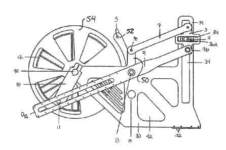
Figure 1 is a partial perspective view of a first embodiment pump jack
apparatus of the present invention for driving a downhole pump via a sucker
rod
string, frame side walls and one drive arm having been omitted for
illustrative
purposes.
Figure 2 is a partial side elevational view of a second embodiment
pump jack apparatus of the present invention, which is similar to that of
Figure 1, this
partial view including the missing side walls and drive arm of Figure 1 while
omitting
some drive system components present in Figure 1.
Figure 3 is a cross-sectional view of the pump jack apparatus of Figure
2 as taken along line A ¨ A thereof.
CA 02770416 2017-02-23
=
9
Figure 4 is an elevational view of a polish rod of the pump jack
apparatus of Figure 1 or 2, illustrating installation of a clamp on the polish
rod for use
in securing the polish rod to a carrier bar of the apparatus.
Figure 5 is a side elevational view of the pump jack apparatus of
Figure 2 at another point in its pump rod reciprocation cycle.
Figure 6 is a schematic front elevational view of a third embodiment
pump jack apparatus.
Figure 7 is a first side elevational view of the third embodiment pump
jack apparatus, but with the drive crank thereof in a different rotational
position.
Figure 8 is a second side elevational view of the pump jack apparatus
of Figure 7 from the opposing side thereof, with a motor and gearbox thereof
omitted.
Figure 9 is a schematic elevational view of a carrier bar support
arrangement of the pump jack apparatus of Figures 6 to 8.
DETAILED DESCRIPTION
The mechanical pump jacks shown in the drawings are each
configured to be fastened onto a wellhead flange by way of a conventional
stuffing
box flange or pedestal stand that is mounted on the wellhead flange to present
a
base plate for supporting the apparatus above the stuffing box. Base plate 2
of the
pump jack apparatus is bolted to the top of the pedestal stand or stuffing
box. The
polish rod 1 extends upwardly through the stuffing box of the wellhead to the
pump
jack apparatus, where it continues through an opening in the base plate 2 and
then
upwardly through a carrier bar 21. Polish rod 1 is secured to the carrier bar
21 for
CA 02770416 2017-02-23
reciprocal up and down movement therewith through a combination of gravity and
a
clamp 19 (Fig. 4) fastened to the polish rod 1 above the carrier bar 21. As a
motor
16 of the apparatus (which may be hydraulic or electric) rotates, its output
shaft
drives the input of a planetary gearbox 17, the output shaft of which has a
sheave 20
5 on its end for driving a belt 15. The planetary gearbox 17 is bolted on a
planetary
support bracket 18. The belt 15 wraps around the planetary sheave 20. The belt
15
then is wrapped around a crank sheave 12. A belt tensioner 14 is used to keep
sufficient pull on the belt 15 as it rotates around the crank sheave 12. The
motor and
the planetary gearbox 17 will rotate the sheave 20, which moves the belt 15
that
10 drives the crank sheave 12. The crank sheave 12 will rotate the same
direction as
the sheave 20. As the crank sheave 12 rotates, a respective cam follower 11
carried
on each side of the crank sheave 12 to revolve about the crank sheave axis
under
rotation of the sheave moves along a recessed or cut-out slot 22 in a
respective
pitman drive arm 9 on the same side of the sheave. A pivot shaft 13 which
pivotally
carries the pitman arms 9 on side walls of the apparatus frame allows the
pitman
arms 9 to rise at one end while lowering at the other, and vise versa. As the
geometry of the crank sheave 12 and attached cranks 10 rotate to pivot the
parallel
pitman drive arms 9, it lowers the rear end of the pitman arms at the crank
wheel
and raises the carrier bar at the front end of the pitman arms upwards, and
vise
versa.
As the front end of pitman arms 9 is rising, carrier bar supports 3 (each
fastened to a respective one of the pitman arms) rise. The carrier bar 21 has
a cam
follower 4 attached to it on each end. The cam follower 4 experiences
horizontal
CA 02770416 2017-02-23
11
motion relative to the carrier support 3 within a carrier support slot 3a
therein to
accommodate the change or orientation of the pitman arm without straining the
polish rod 1. On each side of the apparatus, a carrier bar support arm 7 keeps
the
carrier support 3 vertical to maintain the horizontal orientation of its slot
3a. When
the cam follower 11 reaches its turning (i.e. direction reversing) point in
the cut out
slot 22 on the pitman arm 9, the polish rod 1 begins to go downward. When the
polish rod 1 is going downward the clamp 19 (fastened above the carrier bar
21)
travels down with the carrier bar 21, as the weight of the polish rod and
clamp act to
keep the clamp seated atop the carrier bar 21. Thus, as the front end of the
pitman
arms 9 lower, the polish rod 1 lowers. Once this happens, the process happens
all
over again.
Referring to Figure 1, a lifting support bracket 8 has a lifting ring 5
which is used to lift the machine when attaching to the wellhead. A splash pan
6 is
used to prevent residue from collecting on the rest of the machine. Typically
this is
caused by a stuffing box or a Polish rod scoring. Although described above as
employing belts and sheaves to transfer output from the motor to a drive
crank, this
machine may alternatively employ a gear train, for example housed in a hollow
metal
gearbox, instead of belts and sheaves to complete this rotational coupling
between
the motor and crank.
Further detail of the pumpjack apparatus will now be described with
reference to the drawings.
In addition to the base plate 2 and planetary bracket 18 of Figure 1, the
frame of the apparatus features a pair of identical planar vertical side walls
30, which
CA 02770416 2017-02-23
12
are shown in Figures 2 and 3 and are parallel and aligned with one another in
respective vertical planes. At a front end of the side walls, the base plate 2
spans
horizontally between, and is fixed to, the side walls 30 at their bottom ends,
for
example by bolts fastened into threaded holes 2a in side edges of the base
plate 2
through bolt holes 32 in the side walls 30. Each side wall 30 has a vertically
upright
portion 33 projecting upward from the base plate 2, as shown in Figure 2, and
each
such upright portion 33 features a vertically extending longitudinal guide
slot 34 cut
through it. A respective one of the two carrier supports 3 resides adjacent
the outer
face of each side wall 30 a short distance therefrom, with a portion of the
horizontal
guide slot 3a of the carrier support 3 overlapping the vertical guide slot 34
at any
given time.
In the first two illustrated embodiments, each carrier support 3 is a
cross-shaped metal plate having pivotal connections to the front ends of the
drive
arm 9 and carrier support arm 7 at the bottom and top ends, respectively, of
its
vertically crossing portion, and having its guide slot 3a formed in the
horizontal
crossing portion. The two arms 7, 9 are disposed to the outer side of the
carrier
support, i.e. on the side thereof opposite the respective side wall 30 of the
apparatus
frame. As best shown in Figures 1 and 3, the carrier bar 21 extends
horizontally
between the two side walls 30 of the frame, extending its ends outwardly
through the
vertical guide slots 34 therein. At each of these ends of the carrier bar 21
outside
the frame side walls 30, a respective cam follower 4 is rotatably journaled in
the end
of the carrier bar and disposed within the horiziontal guide slot 3a of the
respective
CA 02770416 2017-02-23
13
carrier support 3 to roll back and forth in the guide slot 3a against the
different
horizontal edge boundaries thereof during operation of the machine.
Where the carrier bar 21 passes through each vertical guide slot 34 in
the upright portion 33 of the respective side wall 30 of the frame, a larger
follower 36
is rotatably journaled around the carrier bar 21 to likewise rollingly ride up
and down
the vertical guide slot 34 against the different vertical boundary edges
thereof during
operation of the machine. As shown in Figures 2 and 3, an outer end of each
vertical slot follower 36 features an outwardly extending flange 36a having an
outer
diameter exceeding that of the rest of the follower and being larger than the
width of
the vertical guide slot 34. The flanges of the two vertical followers 36 thus
define
stops projecting outward from the carrier bar 21 at locations outward from the
side
walls 30 to limit lateral sliding of the carrier bar 21 in either direction
and thereby
block withdrawal of the carrier bar 21 from either vertical slot 34.
The pivot shaft 13 of the drive arm 9 is rotatably journaled in the two
side walls 30 at a position spaced horizontally therealong from the vertical
guide slot
34 therein. The pivot shaft 13 spans between the sidewalls and projects
laterally
outward therebeyond on each side, where it is then fixed to the respective one
of the
drive arms 9 to pivotally carry the drive arms on the frame for pivotal motion
within
respective parallel vertical planes on opposite sides of the frame. The pivot
shaft is
located at an elevation between the upper and lower ends of the vertical guide
slot
34, and in the illustrated first and second embodiments, at a short distance
below
the halfway point of the vertical slot length. Another pivot shaft 38 is
likewise
rotatably mounted on the two side walls to project laterally outward from each
and
CA 02770416 2017-02-23
14
pivotally support the respective one of the two carrier support arms 7 for
pivotal
motion parallel to the respective drive arm 9 along the same vertical plane
thereas.
This support arm pivot shaft 38 is positioned at higher elevation than the
drive arm
pivot shaft 9 at a position directly overhead thereof (i.e. vertically, but
not horizontally
spaced, from the drive arm shaft 13 along the plane of the side wall).
With the two pivot shafts 13, 38 spaced apart only vertically, and the
pivotal connections between each carrier support 3 and the two respective arms
7, 9
likewise being only vertically separated, the parallel arms 7, 9 on each side
of the
frame cooperate with the frame and the respective carrier support 3 to form a
four
bar parallel linkage: one bar defined by the drive arm 9 between it's pivotal
connections to the carrier support 3 and the frame's side wall, a second bar
defined
parallel to the first by the carrier support arm 7 between its pivotal
connections to the
carrier support 3 and the frame's side wall, a third vertical bar defined by
the frame's
side wall 30 between its pivotal connections to the two arms 7, 9, and a
fourth
vertical bar defined parallel to the third by the carrier support's vertical
span between
its pivotal connections to the two arms 7, 9. By way of this parallelogram
linkage,
the carrier support 3 is maintained in a constant vertical orientation, which
positions
its guide slot 3a in a constant horizontal orientation, throughout any pivotal
motion of
the arms 7, 9. The carrier support's slot 3a accommodates the relative
horizontal
displacement necessary between the carrier bar 21 and the carrier support 3 to
allow the drive arm's arcuate motion about its pivot shaft to displace the
carrier bar
21 along the linear vertical constraint defined by the engagement of the
carrier bar
followers 36 in the vertical guide slot 34.
CA 02770416 2017-02-23
The side walls 30 of the frame extend away from the vertical guide slot
34 past the pivot shafts 13, 38 of the arms 9, 7, where near a rear end of the
side
walls distal to the vertical guide slot 34, the crank sheave 12 is mounted on
a
horizontal shaft 40 rotatably journaled in the two side walls 30. The crank
sheave 12
5 is disposed between the side walls, and its shaft 40 projects laterally
outward past
the side walls 30 where it carries a respective crank plate 10 that is fixed
on the
shaft 40 for rotation therewith in a plane perpendicular thereto. At a
distance radially
outward from the shaft 40, the crank plate 10 features a crank pin projecting
laterally
outward therefrom in a direction perpendicular to the crank plate to rotatably
carry
10 the cam follower 11 that is rollably engaged in the drive arm's
longitudinal slot 22
that extends from near a rear end of the drive arm 9a to near the pivot shaft
13
thereof. The drive arm's pivot shaft 13 is located between the crank sheave
and the
vertical guide slot 34 along the side walls of the frame at a distance further
radially
outward from the crank shaft axis than the crank pin follower 11. The slot 22
in the
15 drive arm 9 is long enough to accommodate travel of the crank pin follower
11
through full 360-degree rotation of the crank shaft 40 and attached crank
sheave 12
and crank plate 10 (i.e. through full 360-degree revolution of the crank pin
and crank
pin follower around the crank shaft axis).
Comparing Figures 1 and 2, at least one of the side walls features an
opening 42 located therein below the parallelogram linkage near the bottom of
the
side wall at a location between the vertical guide slot and the crank assembly
to
accommodate connection between the motor driven gearbox 17, located outward
from one of the side walls, to the sheave 20 that is disposed between the two
side
CA 02770416 2017-02-23
16
walls 30 and aligns with the crank sheave suspended between the side walls at
the
rear of the machine. The gearbox support bracket 18 is bolted or otherwise
fixed to
the side walls to rotatably carry the sheave 22 between the side walls and
mount the
gearbox housing in a position extending laterally outward through the opening
42 in
the side wall to the motor 16 coupled at the input end of the gearbox. Between
the
crank sheave 12 and this opening 42 for the drive source components, an
additional
mounting hole is provided in each side wall to accommodate support of the belt
tensioner 14.
Figure 2 shows the parallelogram linkage and crank assembly in
neutral positions situating the carrier bar 21 at a neutral midpoint of its
reciprocating
stroke along the vertical guide slot 34. Here, the crank pin follower 11 is
horizontally
inline with the equal-elevation crank shaft 40 and drive arm pivot shaft 13,
thus
positioning the drive arm 9 and parallel support arm 7 in horizontal
orientations. The
motor 16 is driven in a predetermined direction, and the gearbox output sheave
20
and the crank sheave 12 (and thus the crank shaft 40 and attached crank plate
10)
are driven in the same direction. For example, with reference to Figure 2,
clockwise
driven rotation of the sheaves would initially raise the crank pin follower 11
from its
illustrated position rearward of the crank shaft 40, thus lifting the rear end
9a of the
drive arm 9 and lowering the front end 9b of the drive arm, thereby driving
the carrier
assembly (carrier support, carrier bar and attached followers) near this front
end 9b
downward along the vertical guide slot 34 from the neutral position. As the
crank pin
follower 11 moves arcuately past its uppermost point in its revolution and
begins
moving downward, it reaches a point where its rolling engagement in the drive
arm
CA 02770416 2017-02-23
17
slot 22 begins pulling the rear end 9a of the drive arm downward. Figure 1
shows
the machine in an operation condition near this transition point, where the
carrier
assembly is at the lowermost extent of its travel along the vertical guide
slot 34.
From here, the lowering of the rear end of the drive arm under the effect of
the crank
pin follower lifts the front end of the drive arm 9, and thus also the carrier
assembly,
back up to their neutral positions with the crank pin follower 11 horizontally
inline
with (i.e. at equal elevation to) the crank shaft and drive arm pivot shaft.
As the
crank pin follower 11 passes downward through this neutral position, and
continues
to pull the rear end 9a of the drive arm 9 downward with it, the front end 9a
of the
drive arm and the carrier assembly continue to rise. As the crank pin follower
11
moves arcuately past its lowermost point in its revolution and begins moving
upward,
it reaches a point shown in Figure 5 where its rolling engagement in the drive
arm
slot 22 begins pushing the rear end 9a of the drive arm upward, thereby
lowering the
drive arm front end 9b and carrier assembly from this uppermost point of their
stroke
back to the neutral position of Figure 2. Continued rotation repeatedly drives
this
cycle, thus reciprocating the carrier assembly and attached polish rod through
upward and downward strokes along the vertical guide slot 34.
The polish rod 1 extends through the carrier bar 21 at a through-hole
21a centrally positioned therealong, as shown in Figure 3. Figure 4 shows the
clamp 19 fastened on the polish rod 1, which can be used at a position above
the
carrier bar 21 to block sliding of this clamped position of the polish rod 1
downward
through the carrier bar, as the span of the clamp 19 outward from the polish
rod
exceeds the clearance between the polish rod circumference and the boundary of
CA 02770416 2017-02-23
18
the carrier bar's through-hole 21a. In other words, the diameter of the clamp
across
the polish rod exceeds the diameter of the through-hole 21a. The illustrated
clamp
19 features two halves that are hinged together and that feature channels of
arcuate
cross-section in sides of the halves that face together under closing of the
hinge.
The channels embrace against opposite sides of the polish rod's circumference
as
the halves are closed toward one another across the rod, and a bolt mechanism
distal to the hinged-together ends of the halves is engagable between the
halves
after positioning thereof across the rod to draw the two halves closer
together,
thereby tightening the halves against the rod to clamp the rod between them.
Clamped tightly on the rod, the clamp is seated atop the carrier bar 21,
thereby
hanging the lower end of the polish rod downward from the carrier bar. Below
the
stuffing box of the wellhead, the polish rod is coupled to sucker rods beneath
it in a
conventional manner to complete the pump rod string that is reciprocated by
the
pump jack machine to operate a reciprocally driven downwhole pump.
The splash pan 6 of Figure 1 is mounted between the upright portions
33 of the frame side walls 30 of Figure behind the vertical guide slots 34
therein, i.e.
to the side of the slot nearest crank assembly at the rear of the machine. The
embodiments of Figures 1 and 2 differ only in some details of their structure,
but
operate for sucker rod string reciprocation in the same general manner. Some
of the
differences include the shape of the crank plates 10 and crank sheaves 12, the
positioning in Figure 1 of the lifting ring 5 on a lifting support bracket 8
formed by
joining together the upstanding parts 50 on the side walls that pivotally
carry the
support arms 7 instead of on a separate upright 52 in Figure 2, the presence
of a
CA 02770416 2017-02-23
19
crank sheave protective guard 54 fixed to the inside of each side wall 30 in
Figure 2,
and the difference between a through-slot vs. recessed-slot in the drive arm 9
for
receiving the crank pin follower 11. Other possible variations include, but
are not
limited to, use of slider and slot engagement versus a rolling cam follower
and slot
engagement for constrained relative movement of elements, use of vertical
versus
non-vertical obliquely sloped orientation of the linkage bars formed by the
frame and
the carrier support in the parallelogram linkage while still maintaining the
carrier
support slot in a horizontal orientation perpendicular to the frame's vertical
guide
slot, and positioning of the support arm below versus above the drive arm.
Figures 6 to 9 illustrate a third embodiment pump jack apparatus. Like
the other embodiments, the frame features two planar vertical side walls 30a,
30b
projecting upward at opposite sides of a base plate 2, but each side wall
extends
only upward from the base plate 2, and not in any horizontal direction
therefrom.
The two side walls 30a, 30b share a common overall shape, with obliquely
oriented
sides 102 that diverge from one another in an upward direction in a symmetric
manner across a vertical axis located centrally between them. The perimeter of
each side wall is completed by an arcuate upper edge 104 spanning over 180-
degrees to convexly interconnected the linearly sloped side edges. At its
central
vertical axis, each side wall 30a, 30b features a vertically extending
longitudinal
guide slot 34 cut through it, like in the preceding embodiments for the same
purpose
of guiding the cam followers 36 of the carrier bar 21. In the third
embodiment, the
outer flange 36a of each cam follower extends outward past linear guide tracks
100
CA 02770416 2017-02-23
mounted on opposing vertical sides of the vertical guide slot 34 to lie at
least partially
inward from the sides of the slot on the outside of the respective side wall.
With reference to Figure 8, one of the side walls 30a features a circular
through hole 106 that lies concentric with the radial center of the arcuate
upper edge
5 104 of the wall 30a. Referring to Figure 7, the other side wall 30b
features a larger
circular through hole concentric with that of the other wall. A slewing
bearing 108
has its annular inner race 110 fixed to the inner face of the first side wall
30a around
the circular hole 106 therein, for example through bolt holes 110a passing
axially
through the inner race 110 and matching bolt holes 112 in the side wall 30a.
In a
10 known manner, the outer annular race 114 of the slewing bearing 108
closes around
the inner race thereof, is rotatable around the inner race and has gear teeth
114a
defined at the outer circumference of the race 114.
Referring to Figure 8, a smaller hole 116 located radially outward from
the central hole 106 in the top portion of the first side wall 30a is
surrounded by bolt
15 holes 118 spaced around the circumference of this smaller hole for
mounting of a
gearbox 17 and motor 16 to the exterior face of the first side wall 30a, as
shown in
Figure 6. An output shaft of the gearbox 17 passes through the hole 116 in the
side
wall 30a and carries an output gear 118 in the space between the two side
walls
30a, 30b. This output gear 118 of the gear box engages with the teeth 114a of
the
20 outer race 114 of the slewing bearing 108. Accordingly, operation of the
motor
drives rotation of the slewing bearing's outer race.
On an annular inner face of the movable outer race 114 of the slewing
bearing, i.e. on the side of the outer race facing the second side wall 30b,
is
CA 02770416 2017-02-23
21
mounted a flat or plate-like and arcuately shaped spacer 120 having bolt holes
120a
spaced therealong for cooperation with axial bolt holes 114b circumferentially
spaced around the outer race 114 of the slewing bearing. A bolt 124 has the
threaded free end of its shaft engaged in a threaded hole in the spacer 120,
but
leaves a substantial portion of the shaft length project from the spacer in a
direction
parallel to the axis of the slew bearing at a radial distance outward
therefrom. A
sleeve or hollow block 126 is rotatable disposed on the shaft of the bolt
between the
bolt head 124a and the spacer 120.
The drive arms 9' of the third embodiment are fixed to respective ends
of the sleeve 126 to suspend the drive arms from the shaft of the bolt 124 in
a
manner pivotal thereabout. Accordingly, the outer race of the slewing bearing
defines the crank of this embodiment, with the bolt thus defining the crank
pin about
which the drive arms 9' are pivotal at one end. The rotational axis of the
slewing
bearing lies in the same vertical plane as the axis of the carrier bar 21, and
so
horizontally-slotted carrier bar support of the first two embodiments is not
needed in
the third embodiment. Accordingly, the second ends of the drive arms 9' are
pivotally coupled directly to the carrier bar, requiring only pivotal motion
of the drive
arms 9' about the axis of the carrier bar to accommodate linear motion thereof
along
the vertical guide slots in the side walls of the frame under rotation of the
slewing
bearing.
An unillustrated earlier prototype of third embodiment featured a single
drive arm structure with a single connection to the crank pin bolt 124 and a
branched
or forked lower end that split to connect to the carrier bar 21 on opposite
sides of the
CA 02770416 2017-02-23
22
polish rod 1. However, the illustrated embodiment with two entirely separate
drive
arms located entirely on respective sides of the polish rod 1, and thus
separately
connecting to the crank pin bolt 124 at spaced positions therealong, is
preferred so
as to provide maximum space above the carrier bar 21 to maximize the
accommodation of movement of the top end of the polish rod 1 above the carrier
bar
21. This prevents the polish rod from bending when it is not traveling with
the carrier
bar downwards due to waxing/sanding of the well or downhole issues. In such
situations, the polish rod is in the air and while the carrier bar moves
upwards. The
separate, spaced-apart carrier bar support/drive arms 9' allow the polish rod
to go
between the two arm supports. This prevents bending of the polish rod and
weIlhead damage. The top end of the polish rod 1 may be equipped with a
threaded
polish rod coupling, as shown in Figure 6 at 128.
The third embodiment shares the two-sided support and guidance of
the of the polish rod carrier bar 21 for optimal performance in maintaining
the
desired orientation of the polish rod, but avoids the need for the additional
horizontal
guide slots of the first two embodiments by having the rotational axis A of
the crank
located directly overhead of the carrier (i.e. by having the crank vertically,
but not
horizontally spaced from the vertical guide slots at which the carrier bar
runs up and
down the side walls of the frame). Although omitted for illustrative purposes,
it will
be appreciated that the two side walls of the frame are preferably linked by
cross-
bars, plates, grates or other members at locations along the edges of the
plates
around the components located therebetween to provide rigidity to the
structure, and
to provide protection from the moving parts therebetween. Of course, closure
CA 02770416 2017-02-23
23
panels spanning between the walls at one more locations would preferably be
removable to allow access to the internal components. The third embodiment
also
illustrates that the invention is not limited to a belt drive configuration
like the first two
embodiments. Through testing of prototypes of the different embodiments, the
belt
drive of the first two has proven less reliable than the gear driven third
embodiment.
It will be appreciated that different components from the different
embodiments may combined in arrangements not illustrated herein. For example,
a
further embodiment could employ the more horizontally-oriented design of the
first
two embodiments where the crank is horizontally spaced from the guide slot of
the
polish rod carrier, and thus may use the correspondingly slotted drive arms
pivotally
mounted on the frame, while replacing the belt-driven crank sheave with a slew-
bearing or other toothed gear structure for improved reliability and wear-life
of the
drive system. Another possible combination could employ a belt or chain driven
transmission arrangement like that of the first tow embodiments in an overhead
drive
configuration like that of the third embodiment, thereby avoiding the need for
the
slotted carrier bar supports 3 of the first two embodiments.
Since various modifications can be made in my invention as herein
above described, and many apparently widely different embodiments of same made
within the scope of the claims without departure from such scope, it is
intended that
all matter contained in the accompanying specification shall be interpreted as
illustrative only and not in a limiting sense.