Note: Descriptions are shown in the official language in which they were submitted.
CA 02770434 2012-02-07
DESCRIPTION
A process analyzer
The invention refers to a process analyzer for determining an analyte in a
liquid under analysis and is used, for example, in the form of an immersion
probe, a swimming probe, a tube probe or a laboratory analyzer.
Process analyzers quasi-continuously perform analyses for a quantitative
determination of an analyte in a liquid under analysis, such as in water, and
find application in waste water treatment or drinking water control for ex-
ample.
Since a process analyzer is generally not used in laboratories, and mainte-
nance, repair, and refilling carrier liquid and reagents are considerable ef-
forts, modular process analyzers are meanwhile available wherein low-
maintenance or maintenance-free components are arranged in a base mod-
ule and components that are delicate, exposed to wear, or sore reagents
are arranged in an exchangeable cartridge module. It is also possible to
provide a plurality of different exchangeable cartridge modules, for instance
comprising reservoir tanks and fluidic systems.
Such a modular structure of a process analyzer is known, for example, from
EP 0 706 659 131. Here, a part of the fluidic system and a dialysis mem-
brane are arranged in a cartridge module, whereas the pumps and the res-
ervoir tanks for the carrier liquid and the reagent are provided in the base
module.
It is desirable in principle to arrange the used material, i.e. the carrier
liquid
and the reagent, in the cartridge module as well. However, this requires
that only rather small volumes of carrier liquid and reagent are used. This,
CA 02770434 2012-02-07
2
in turn, can be achieved by designing the fluidic system as a so-called mi-
crofluidic system, i.e. by designing the liquid conduits with small sectional
areas, for example sectional areas of less than a few square millimeters.
However, microfluidic systems are inherently more trouble-prone than flu-
idic systems with larger sections.
It is an object of the invention to provide a process analyzer comprising a
base module and an exchangeable cartridge module, which analyzer is reli-
able and in which the reagent is stored in the cartridge module.
The object is achieved, according to the invention, with the process analyzer
having the features of claim 1.
The process analyzer of the present invention is formed by a base module
which is basically not exchangeable and an exchangeable cartridge module
that can be exchanged with little effort at regular intervals, for example
when the carrier liquid supply or the reagent supply is depleted or a compo-
nent is defect. The cartridge module includes the entire fluidic system which
preferably is of a microfluidic design, i.e. all liquid carrying elements have
very small volumes or very small sectional areas of a few square millimeters
at most, for example a maximum of 10 square millimeters, preferably of
less than five square millimeters.
The cartridge module comprises a sample taking device, preferably a dialy-
sis device, with a membrane, preferably a dialysis membrane, for obtaining
a sample, preferably a dialysate, from the liquid under analysis. In case of a
dialysis, the sample is a dialysate formed by a carrier liquid and the analyte
from the liquid under analysis, with the analyte migrating through the
membrane into the carrier liquid. A first pump mechanism is provided for
the purpose of pumping the carrier liquid from a carrier liquid reservoir tank
which preferably is arranged in the cartridge module, to the sample taking
device. A pump mechanism is to be understood as a mechanical system
that pumps a liquid. The pump mechanism is preferably designed as a dis-
CA 02770434 2012-02-07
3
placement pump. The pump mechanism is driven by an actuator system
that preferably is arranged in the base module, separately from the pump
mechanism. Thus, the cartridge module preferably includes no actuator sys-
tem. If the sample taking device is a filter for filtering a sample, no
carrier
liquid reservoir tank is provided.
The cartridge module comprises a second pump mechanism for introducing
a reagent from a reagent reservoir tank into the sample. It also applies to
the second pump mechanism that the associated actuator system is pref-
erably arranged in the base module. Further, the cartridge module com-
prises a measuring section for the quantitative determination of the analyte
in the sample or in the dialysate. Preferably, the measuring section is an
optical measuring section for the photometric quantitative determination of
an analyte.
The cartridge module further comprises a degassing device for degassing
the sample or the dialysate in the course of the liquid conduit that leads
from the sample taking device to beyond the measuring section, the de-
gassing device being arranged behind the two pump mechanisms. Thus,
seen in the flow direction, the degassing device is arranged behind the
sample taking device and behind the two pump mechanisms. By arranging
the degassing device behind the pump mechanisms it is guaranteed that
gas bubbles are removed from the sample before the same flows into the
measuring section. This is so important because gas bubbles can lead to
substantial errors during measurement, in particular in an optical measuring
section in which the analyte is quantitatively determined by photometry.
Gas bubbles may be formed in a sample when the sample in the cartridge
module becomes warmer, for example due to a warm liquid under analysis
that is present at the dialysis membrane. Further, an acid reagent in the
sample can expel carbon dioxide gas. By arranging the degassing device
behind the point where the reagent is introduced into the sample, it is guar-
anteed that the expelled carbon dioxide gas is removed from the sample as
CA 02770434 2012-02-07
4
well before the sample flows into the measuring section. Thus, the reliabil-
ity, the measuring certainty and the measuring accuracy are improved.
Preferably, both pump mechanisms are driven pneumatically by a pneu-
matic pump on the base module side. The pressure side of the pneumatic
pump maybe connected to an overpressure accumulator and the suction
side may be connected to a vacuum accumulator. The overpressure accu-
mulator and the vacuum accumulator are arranged in the base module.
The degassing device comprises a gas-permeable degassing membrane
which is connected to the pneumatic pump of the base module to generate
a vacuum on the gas side of the degassing membrane. The pump mecha-
nisms may, for example, be designed as pneumatically driven peristaltic
pumps, each having two or three pump chambers. Thus, a single pneumatic
pump can form both the actuator system of the two pump mechanisms and
generate the vacuum on the gas side of the degassing membrane. For this
purpose it is merely necessary to provide corresponding valves to control
the pump mechanisms or the peristaltic pumps, respectively. The reduction
to a single pneumatic pump for driving the pump mechanisms and for the
degassing device results in a substantial reduction in design effort and
manufacturing effort. Further, less energy is required for the operation of
the analyzer which is of great importance in particular with battery-powered
analyzers.
Preferably, the degassing device is formed by a groove-shaped degassing
channel covered by a gas-permeable degassing membrane. For example,
the degassing channel may be formed as a groove in an injection molded
base plate on which the degassing membrane is fastened in the region of
the degassing device, e.g. by gluing or welding. It is particularly preferred
for the degassing channel to extend in a meandering manner. This allows
realizing the degassing device and the degassing membrane with rather
small areas. It is particularly preferred to configure the degassing mem-
brane as a hydrophobic membrane, for example, a Teflon membrane.
CA 02770434 2012-02-07
Preferably, the volume of the degassing channel is at least as large as the
volume of the measuring section. Thereby, it is made sure that the entire
measuring section can be filled with a degassed sample volume and that
there is no part of the sample in the measuring section that is not de-
gassed.
In a preferred embodiment the volume of the degassing channel is at least
as large as the sum of the volumes of the space proximal of the membrane
of the sample taking device and the reagent introduced. In this manner, all
of the sample volume of a measuring cycle, mixed with the reagent, can be
degassed in the degassing device. Irrespective of which part of this sample
volume eventually fills the measuring section, it is thus guaranteed that the
sample volume that has reached the measuring section has been degassed.
In a preferred embodiment the degassing channel is a reaction space in
which the mixture of sample and reagent dwells for at least 10 seconds be-
fore it is pumped to the measuring section. A separate reaction chamber,
used to wait for the reaction of the reagent with the analyte in the sample,
is not needed. If the reagent is acidic and expels carbon dioxide gas from
the sample, it is thus guaranteed that the carbon dioxide gas is withdrawn
from the sample at the very site at which it is formed. Thus, a change in the
volume of the sample during the reaction with the reagent is avoided. The
sample/reagent mixture dwells in the reaction space until the reaction of
the reagent and the analyte is substantially finished. Thereby, it is made
sure that no further carbon dioxide gas is expelled from the sample after it
has lest the degassing device, which gas could impair or corrupt the subse-
quent measurement in the measuring section.
In a preferred embodiment the cartridge module comprises a carrier liquid
reservoir tank and a reagent reservoir tank. The entire fluidic system is thus
arranged in the cartridge module. The volumes of the two reservoir tanks
are designed such that the reservoir will last for the duration of the normal
CA 02770434 2012-02-07
6
mechanical functionality of the cartridge module. In this respect it is feasi-
ble to dimension the entire fluidic system as a microfluidic system. The res-
ervoir tanks may be provided on the cartridge module such that they are
exchangeable.
In a preferred embodiment, the base module comprises a photometric ana-
lyte sensor that is functionally associated to the measuring section on the
cartridge module side. Thus, the base module comprises a photometer,
wherein the measuring section of the photometer is formed by the measur-
ing section in the cartridge module when the cartridge module is placed in
the base module.
In a preferred embodiment the degassing device is arranged between the
two pump mechanisms on the one hand and the measuring section on the
other hand. Thereby, it is made sure that the dialysate is completely de-
gassed before entering the measuring section. It is particularly preferred to
arrange the degassing device or the degassing channel, respectively, imme-
diately upstream of the measuring section. As an alternative or in addition,
the degassing device may also be arranged along the measuring section
itself. In this manner, the dialysate can also be degassed during the meas-
urement in the measuring section. This is particularly feasible for a photo-
metric measuring section, since gas bubbles may corrupt photometric mea-
surement results, especially if the measuring section is a microfluidic meas-
uring section.
The following is a detailed description of an embodiment of the invention
with reference to the drawing.
In the Figures:
Figure 1 is a schematic illustration of a process analyzer formed by a
base module and an exchangeable cartridge module,
CA 02770434 2012-02-07
7
Figure 2 is a longitudinal section of a second embodiment of an analyzer,
Figure 3 is a top plan view on the cartridge module of the analyzer in
Figure 2, and
Figure 4 a further embodiment of a degassing device of an analyzer car-
tridge module.
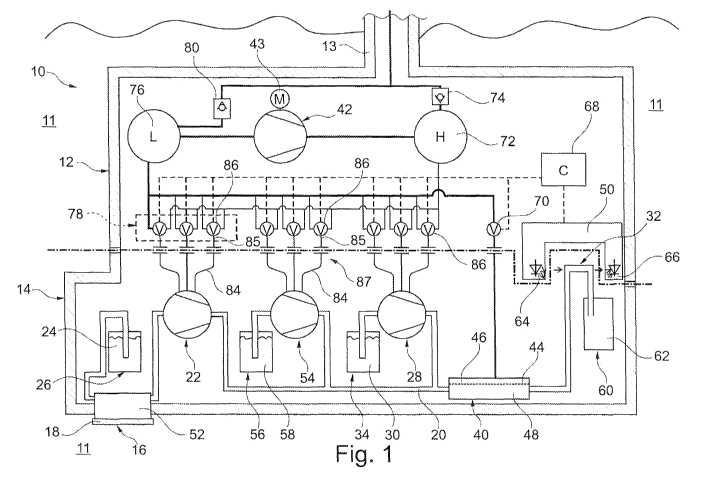
Figure 1 is a schematic illustration of a process analyzer 10 for a continuous
or quasi-continuous quantitative photometric determination of an analyte,
for example phosphate, ammonium or nitrate, in water. The analyzer 10 is
a stationary analyzer 10 and is mounted immersed in an aqueous liquid 11
under analysis, i.e. it is designed as a so-called immersion probe. The ana-
lyzer 10 comprises a base module 12 rigidly suspended from a tubing 13
and hanging in or just above the liquid 11 under analysis, and an ex-
changeable cartridge module 14 removably fastened to the base module 12
and immersed into the liquid 11 under analysis.
The entire fluidic system of the analyzer 10 is provided in the cartridge
module 14. The cartridge module 14 comprises a carrier liquid reservoir
tank 26 with a carrier liquid 24 connected to a sample taking device 16 via
a conduit, which device is a dialysis device 16 in the present case. As its
membrane 18, the dialysis device 16 has a dialysis membrane 18 that sepa-
rates the dialysis chamber 52, in which the carrier liquid dwells during the
dialysis, from the liquid 11 under analysis. The dialysis chamber 52 may, for
example, be formed by a meandering groove whose grove opening is closed
by the dialysis membrane 18. A first pump mechanism 22 is provided be-
hind the dialysis device 16, the pump mechanism pumping the sample 20 or
the dialysate from the dialysis device 16 to a degassing device 40.
The cartridge module 14 comprises a reagent reservoir tank 34 containing a
liquid reagent 40 pumped to the degassing device 40 by a second pump
mechanism 28. Further, a standard solution reservoir tank 56 containing a
CA 02770434 2012-02-07
8
standard solution 58 is provided in the cartridge module 14, wherein a third
pump mechanism 54 is provided downstream of the standard solution res-
ervoir tank 56, seen in the flow direction, which pump mechanism pumps
the standard solution to the degassing device 40, if needed
The three pump mechanisms 22, 28, 54 converge in a star-shaped manner
just before the degassing device 40, as is particularly well visible in Figure
3. The degassing device 40 is formed by a groove-shaped degassing chan-
nel 48 covered by a gas-permeable and liquid-tight degassing membrane 44
which is a hydrophobic Teflon membrane. The degassing channel extends in
a meandering manner so that a relatively long degassing channel 48 is real-
ized in a small area. On the side of the degassing membrane 44 opposite
the degassing channel 48, the gas side 46 of the degassing device is ar-
ranged whose evacuation is controlled through a degassing valve 70 on the
base module side.
The sample flows from the degassing device 40 to a photometer measuring
section 32 and from there into a waste liquid tank 60 in which the waste
liquid 62 is collected. The photometer measuring section 32 is functionally
associated to a photometer 50 on the base module side which has a light
source 64 and a receiver 66 between which a section of the dialysate con-
duit is arranged in the longitudinal direction, which section forms the pho-
tometer measuring section. In the present case, the analyte sensor 50 is
designed as a transmission photometer. Alternatively, the photometer may,
however, also be designed as a reflection photometer 50', as illustrated in
the embodiment in Fig. 2.
The pressure sources for driving the three pump mechanisms 22, 54, 28 are
an overpressure accumulator 72 and a vacuum accumulator 76 in the base
module 12. The three pump mechanisms 22, 54, 28 are designed as pneu-
matic peristaltic pumps. A respective pump actuator system 78 is associ-
ated to each pump mechanism 22, 54, 28, each actuator system being
formed by three change-over valves 86. Each pump mechanism 21, 54, 28
CA 02770434 2012-02-07
9
respectively comprises three pump chambers 80 with e respective elastic
pump membrane 82 made of rubber or an elastic plastic material.
The rear side of each pump membrane 82 is connected to a change-over
vale 86 via a pneumatic control conduit 84 on the cartridge module side, a
control conduit coupling 87 and a pneumatic control conduit 85 on the base
module side, the change-over valve selectively connecting the pump mem-
brane 82 with the overpressure accumulator 72 or the vacuum accumulator
76. In this manner, either an overpressure or a vacuum is applied to the
rear side of the pump membrane 82 so that the pump chambers 80 are
filled or emptied. By successively filling and emptying the three pump
chambers 22, 54, 28, a peristaltic pumping movement is caused.
For the purpose of generating a vacuum in the vacuum accumulator 76 and
an overpressure in the overpressure accumulator 72, a pneumatic pump 42
is provided in the base module 12, whose pump inlet is connected to the
vacuum accumulator 76 and whose pump outlet is connected with the over-
pressure accumulator 72. The pneumatic pump 42 is driven continuously by
an electric pneumatic pump motor 43. The vacuum in the vacuum accumu-
lator 76 and the overpressure in the overpressure accumulator 72 are lim-
ited, respectively, by a corresponding vacuum valve 80 or an overpressure
valve 74, each connected to atmospheric air pressure. As an alternative, the
pressure sensors may be provided in the accumulators, by means of which
the pneumatic pump is activated or deactivated when pressure falls below a
limit pressure or exceeds the same.
The degassing valve 70 controlling the vacuum in the degassing device 40
is connected to the vacuum accumulator 76.
All valves 86, 70 and the photometer 50 are controlled by a central control
68. All electric components are arranged in the base module 12.
CA 02770434 2012-02-07
Figures 2 and 3 illustrate a second embodiment of an analyzer or a car-
tridge module 14, respectively. A difference from the embodiment illus-
trated merely schematically in Figure 1 is the concrete design of the three
pump mechanisms 22', whose respective last pump chamber 80' is formed
by a single common pump chamber 80'. Another difference in Figure 2 is
the design of the analyte sensor 50' as a reflection photometer.
As is clearly visible in Figures 2 and 3, the cartridge module 14 is substan-
tially formed by a plate-shaped plastic part comprising the fluidic system
conduits, the pump chambers 80, 80', the dialysis module 16, the degassing
device 40 as well as the measuring section 32', and by the tanks 26, 34, 56,
62 set on the plate-shaped plastic part.
In Figure 4 an alternative embodiment of a degassing device 40' is illus-
trated, wherein a part of the degassing channel 48 at the same time forms
the photometer measuring section 32.
It applies to all embodiments of the degassing device 40, 40' that the vol-
ume of the entire degassing channel 48 is at least as large as the sum of
the volumes of the dialysis chamber 52 proximally of the dialysis membrane
18 and the introduced reagent 30.