Note: Descriptions are shown in the official language in which they were submitted.
CA 02770452 2016-09-26
DISPOSABLE ACOUSTIC COUPLING MEDIUM CONTAINER
FIELD OF THE INVENTION
[0003] The present invention generally relates to acoustically coupling
ultrasound devices
to a patient. More specifically, the present invention relates to acoustically
coupling ultrasound
therapy devices to a patient for treatment of tissue.
BACKGROUND OF THE INVENTION
[0004] Histotripsy and Lithotripsy are non-invasive tissue ablation
modalities that focus
pulsed ultrasound from outside the body to a target tissue inside the body.
Histotripsy
mechanically damages tissue through cavitation of microbubbles, and
Lithotripsy is typically
used to fragment urinary stones with acoustic shockwaves.
[0005] Histotripsy is the mechanical disruption via acoustic cavitation of
a target tissue
volume or tissue embedded inclusion as part of a surgical or other therapeutic
procedure.
Histotripsy works best when a whole set of acoustic and transducer scan
parameters controlling
the spatial extent of periodic cavitation events are within a rather narrow
range. Small changes
in any of the parameters can result in discontinuation of the ongoing process.
[0006] Histotripsy requires high peak intensity acoustic pulses which in
turn require large
surface area focused transducers. These transducers are often very similar to
the transducers
used for Lithotripsy and often operate in the same frequency range. The
primary difference is
in how the devices are driven electrically.
[0007] Histotripsy pulses consist of a (usually) small number of cycles
of a sinusoidal
driving voltage whereas Lithotripsy is (most usually) driven by a single high
voltage pulse with
the transducer responding at its natural frequencies. Even though the
Lithotripsy pulse is only
one cycle, its negative pressure phase length is equal to or greater than the
entire length of the
Histotripsy pulse, lasting tens of microseconds. This negative pressure phase
allows generation
and continual growth of the bubbles, resulting in bubbles of sizes up to 1 mm.
The Lithotripsy
- 1 -
CA 02770452 2016-09-26
pulses use the mechanical stress produced by a shockwave and these 1 mm
bubbles to cause
tissue damage.
[0008] In comparison, each negative and positive cycle of a Histotripsy
pulse grows and
collapses the bubbles, and the next cycle repeats the same process. The
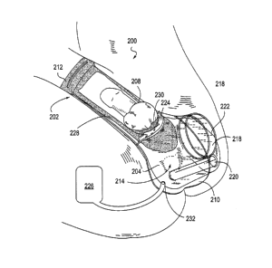
maximal sizes of
bubbles reach approximately tens to hundreds of microns. These micron size
bubbles interact
with a tissue surface to mechanically damage tissue.
[0009] In addition, Histotripsy delivers hundreds to thousands of pulses
per second, i.e.,
100-1kHz pulse repetition frequency. Lithotripsy only works well within a
narrow range of
pulse repetition frequency (usually 0.5-1Hz). Studies show that the efficacy
and efficiency of
lithotripsy decreases significantly when the pulse repetition frequency is
increased to 10-
100Hz. The reduced efficiency is likely due to the increased number of mm size
bubbles
blocking the shock waves and other energy from reaching the stone.
[00010] Histotripsy transducers have a focal point positioned a distance
from the transducer
where the cavitational bubble clouds are formed. In order to non-invasively
treat tissue inside a
patient, the transducers must be positioned away from the patient's skin so as
to locate the
cavitational focal point on the target tissue. Thus, when the transducer is
positioned away from
the patient's skin, the pulsed ultrasound of a Histotripsy ultrasound
transducer must be carried
through an aqueous coupling medium that is in intimate contact with the
ultrasound transducer
and the skin surface.
[00011] One prior solution to acoustic coupling for therapeutic ultrasound
includes a water
bath disposed in a treatment table. During therapy, the patient lies with the
body immersed in
the water bath. This coupling solution is both cumbersome and expensive as it
requires a
specialized examination table and is not versatile or portable. Additionally,
it requires a large
volume of an acoustic coupling medium (typically degassed water) which is
expensive and can
be messy.
[00012] Thus, there is a need for an inexpensive, minimal, and versatile
acoustic coupling
device for use in ultrasonic therapy applications such as Histotripsy and
Lithotripsy.
- 2 -
CA 02770452 2016-09-26
SUMMARY OF THE INVENTION
[00013] In one embodiment, the frame is sized and shaped to conform to a male
patient's
anatomy surrounding the perineum.
[00014] In some embodiments of the ultrasound therapy device, the reservoir
portion is
pliable. In other embodiments, the reservoir portion is transparent. In
another embodiment, the
reservoir portion is open so as to expose the acoustic coupling medium to air.
[00015] In some embodiments, the ultrasound transducer is coupled to the
reservoir portion
and configured to direct ultrasonic therapy through the perineum to the
patient's prostate.
[00016] In one embodiment, the ultrasound therapy device further comprises a
sling
configured to hold the patient's scrotum away from the perineum.
[00017] In many embodiments, the acoustic coupling medium comprises a degassed
water.
In other embodiments, the acoustic coupling medium comprises an acoustic gel.
[00018] In some embodiments of the ultrasound therapy device, the frame is
secured to the
patient with an adhesive. In other embodiments, the frame is secured to the
patient with a strap.
In another embodiment, the frame comprises a wearable garment. The wearable
garment can
provide a liquid seal against the patient's skin near the patient's waist and
near the patient's
legs, for example. Alternatively, the wearable garment can provide a liquid
seal against the
patient's skin around the patient's perineum.
[00019] In some embodiments, the ultrasound therapy device further comprises a
remote
reservoir configured to receive the acoustic coupling medium from the
reservoir portion when
the reservoir portion is compressed and to deliver the acoustic coupling
medium to the reservoir
portion when the reservoir portion is expanded.
[00020] In some embodiments, the ultrasonic transducer is configured to
deliver a histotripsy
pulse to the patient's prostate. In another embodiment, the ultrasonic
transducer is configured
to form cavitation bubbles in the patient's prostate. In yet another
embodiment, the ultrasonic
transducer is configured to deliver acoustic pulses that operate at a
frequency between
approximately 50 KHz and 5MHz, having a pulse intensity with a peak negative
pressure of
approximately 8-25 MPa, a peak positive pressure of more than 10 MPa, a pulse
length shorter
than 50 cycles, a duty cycle between approximately 0.1% and 5%, and a pulse
repetition
frequency of less than 5 KHz.
- 3 -
CA 02770452 2016-09-26
[00021] A method of treating a prostate of a patient is described which
comprises imaging
the prostate with an ultrasound probe, placing an acoustic medium container
over a perineum of
the patient, and applying ultrasonic therapy through the acoustic medium
container to cause
mechanical fractionation of a target portion of the prostate.
[00022] The prostate can be imaged by inserting the ultrasound probe into the
patient's
rectum to image the prostate. The ultrasound probe is inserted into a rectal
sheath to provide a
liquid seal barrier between the ultrasound probe and the patient's rectum.
[00023] The method comprises at least partially filling the acoustic medium
container with
an acoustic coupling medium, such as degassed water. The acoustic coupling
medium directly
contacts the patient's skin. In other embodiments, the acoustic coupling
medium does not
directly contact the patient's skin.
[00024] The method further comprises securing the acoustic medium container to
the patient
with an adhesive. The method comprises securing the acoustic medium container
to the patient
with a strap. The acoustic medium container can be secured to the patient to
form a liquid seal
between the container and the patient's skin.
[00025] The applying step can further comprise applying ultrasonic therapy
with an
ultrasonic therapy transducer coupled to the acoustic medium container. The
applying
ultrasonic therapy step comprises applying histotripsy to treat the patient.
The applying
ultrasonic therapy step comprises forming cavitation bubbles in the target
portion of the
prostate. The applying ultrasonic therapy step comprises applying acoustic
pulses that operate
at a frequency between approximately 50 KHz and 5MHz, having a pulse intensity
with a peak
negative pressure of approximately 8-25 MPa, a peak positive pressure of more
than 10 MPa, a
pulse length shorter than 50 cycles, a duty cycle between approximately 0.1%
and 5%, and a
pulse repetition frequency of less than 5 KHz.
[00026] The applying ultrasonic therapy step comprises applying lithotripsy or
HIFU to treat
the patient.
[00027] The method further comprises expelling a volume of the acoustic
coupling medium
into a remote reservoir from the acoustic medium container when the acoustic
medium
container is compressed, and infusing a volume of the acoustic coupling medium
into the
- 4 -
CA 02770452 2016-09-26
acoustic medium container from the remote reservoir when the acoustic medium
container is
expanded.
[00028] In an embodiment, there is described an ultrasound therapy device,
comprising: a
frame configured to conform to and provide a liquid seal against a patient's
skin, the frame
defining an open aperture; a rectal imaging probe configured to image a
patient's prostate; a
reservoir portion configured to hold an acoustic coupling medium, the
reservoir portion being
configured to provide the acoustic coupling medium in direct contact with the
patient's skin
through the open aperture, the reservoir portion further comprising a sheath
configured to
receive the rectal imaging probe; and an ultrasound transducer coupled to the
frame and in
acoustic communication with the acoustic coupling medium, wherein movement of
the
ultrasound transducer relative to the frame maintains acoustic communication
between the
ultrasound transducer and the acoustic coupling medium.
BRIEF DESCRIPTION OF THE DRAWINGS
[00039] Fig. 1 illustrates one embodiment of an ultrasound coupling
container.
[00040] Fig. 2 illustrates one embodiment of an ultrasound coupling
container attached
to a patient.
[00041] Fig. 3 illustrates another embodiment of an ultrasound
coupling container.
[00042] Fig. 4 illustrates one embodiment of an ultrasound coupling
container attached
to a patient.
[00043] Fig. 5 illustrates one embodiment of an ultrasound coupling
container in the
form of a garment worn by a patient.
[00044] Fig. 6 is an exploded view of one embodiment of an ultrasound
coupling
container.
[00045] Figs. 7-8 are additional views of the ultrasound coupling
container of Fig. 5.
[00046] Figs. 9-10 illustrate one embodiment of an ultrasound coupling
container having
a remote reservoir.
- 5 -
CA 02770452 2012-02-08
WO 2011/022411
PCT/US2010/045775
DETAILED DESCRIPTION OF THE INVENTION
[00047] In addition to imaging tissue, ultrasound technology is increasingly
being used to
treat and destroy tissue. In medical applications such as Histotripsy, where
ultrasound pulses are
used to form cavitational microbubbles in tissue to mechanically break down
and destroy tissue,
it is necessary to acoustically couple the ultrasound therapy transducer to
the patient while
allowing for movement of the therapy transducer in all directions. Particular
challenges arise in
the application of Histotripsy for the treatment of BPH and prostate cancer,
where the male
anatomy provides only a small acoustic window through the perineum to deliver
ultrasound
energy. The present invention describes several embodiments of an ultrasound
coupling
apparatus for acoustically coupling an ultrasound therapy transducer to a
patient. In particular,
the present invention provides for acoustic coupling of ultrasound therapy
transducers, such as
those used in Histotripsy, Lithotripsy, and HIFU, for the treatment of a
variety of medical
conditions including but not limited to BPH and prostate cancer.
[00048] Referring now to Fig. 1, an ultrasound coupling container 100 is
shown comprising a
frame 102 and a pliable reservoir portion 104. The ultrasound coupling
container 100 is
configured to acoustically couple an ultrasound therapy transducer to a
patient to allow for
movement of the ultrasound therapy transducer relative to the patient during
treatment while
maintaining acoustic communication between the transducer and the target
tissue undergoing
therapy.
[00049] Frame 102 can comprise a pliable material that is configured to
conform to a patient's
skin and provide a liquid seal against the patient's skin. The frame may also
include, for
example, foam or another conforming material 103 to improve the liquid seal
between the frame
to skin interface. Referring still to Fig. 1, frame 102 may comprise laterally
opposed first and
second frame portions 106 and 108, and longitudinally opposed third and fourth
frame portions
110 and 112 to define a treatment aperture 114. Frame 102 may incorporate
straps or belts (not
shown) through slits 116, and/or adhesives to help secure the frame of the
ultrasound coupling
container to the patient's skin to form a liquid seal against the patient's
skin.
[00050] As shown in Fig. 1, reservoir portion 104 can be attached to frame 102
and can
extend outward from the frame and aperture 114. Reservoir portion may include
transducer
receptacle 118 configured to hold and position an ultrasound therapy
transducer over treatment
aperture 114. The reservoir portion can comprise a flexible, pliable material
and is configured
to allow for positioning and movement of an ultrasound therapy transducer over
the treatment
aperture 114 during set-up and treatment. In some embodiments, the reservoir
portion 104
comprises a pliable, transparent plastic. The transparent plastic construction
facilitates direct
- 6 -
CA 02770452 2012-02-08
WO 2011/022411
PCT/US2010/045775
visual access to the patient and the contents of the ultrasonic medium
container, which can assist
the operator with set-up and monitoring throughout the treatment procedure. In
the embodiment
shown in Fig. 1, the reservoir portion 104 includes an opening 121, which can
be used to fill the
reservoir portion with an acoustic coupling medium such as degassed water, for
example.
Because the frame 102 defines an open aperture 114, acoustic coupling medium
is allowed to be
in direct contact with the patient's skin when the reservoir portion 104 is
filled.
[00051] The pliable nature of the reservoir portion 104 allows the transducer
receptacle 118,
and thus the ultrasound transducer inserted therein, to be moved with respect
to the patient and
the frame. In therapeutic applications such as Histotripsy, where the relative
position of the
therapy transducer with respect to the target tissue must be adjusted to align
a therapy focal point
with the target tissue, it is necessary to be able to move the therapy
transducer while maintaining
acoustic communication between the transducer and the patient. Thus, in Fig. 1
when the
reservoir portion is filled with an acoustic coupling medium and the reservoir
portion is
compressed (e.g., during positional adjustment of the therapy transducer),
then acoustic coupling
medium may be allowed to spill out of the opening 121 in response to the
change in volume of
the reservoir portion.
[00052] The reservoir portion 104 can further include a sheath 120 for
acoustically coupling a
rectal ultrasonic imaging probe (not shown) to the patient. The sheath can be
a pliable and liquid
impermeable, similar to a condom. This "condom" like sheath 120 can provide a
liquid seal
barrier for coupling the rectal ultrasonic imaging probe to the ultrasound
coupling container and
also can act as the protective barrier for inserting the rectal ultrasonic
imaging probe into the
patient's rectum, as it is typically done in urological trans-rectal imaging.
[00053] Referring now to Fig. 2, an ultrasound coupling container 200 is shown
positioned on
a male patient. As seen in Fig. 2, frame 202 can be positioned on the patient
so that first and
second frame portions 206 and 208 are sized and configured to conform to each
side of the
patient's groin. Third frame portion 210 can be sized and configured to
conform to the patient's
skin below the rectum, and fourth frame portion 212 can be sized and
configured to conform to
the patient's skin above the penis. It can be seen that frame 202 completely
surrounds the
patient's penis, testicles, perineum, and rectum.
[00054] When the ultrasound coupling container 200 is positioned as shown in
Fig. 2,
transducer receptacle 218 can be positioned directly above the patient's
perineum so as to have a
direct acoustic window towards the prostate. Sheath 220 can then be aligned
with the patient's
rectum to allow for insertion of a rectal ultrasonic imaging probe for trans-
rectal imaging of the
prostate.
- 7 -
CA 02770452 2012-02-08
WO 2011/022411
PCT/US2010/045775
[00055] The pliable nature of the reservoir portion 204 allows the transducer
receptacle 218,
and thus the ultrasound transducer inserted therein, to be moved with respect
to the patient and
the frame. In the embodiment of Fig. 2, the ultrasound coupling container 200
is shown filled
with an acoustic coupling medium 222 to provide acoustic communication between
the
transducer receptacle 218 and the patient. It can be seen that the aperture
214 defined by frame
202 allows the acoustic coupling medium 222 to directly contact the patient's
skin in the region
surrounding the perineum. Furthermore, in contrast to the embodiment of Fig. 1
which included
an opening 121 to allow spillover of acoustic coupling medium, the embodiment
of Fig. 2 can
include a seal 224 to keep the acoustic coupling medium 222 fully contained
within the device.
When reservoir portion 204 is filled with an acoustic coupling medium the
acoustic coupling
medium is allowed to be in direct contact with the patient's skin. However,
movement of the
therapy transducer can cause the volume of the reservoir portion to change, so
the ultrasound
coupling container 200 of Fig. 2 can further include a remote reservoir 226
coupled to the
reservoir portion. The remote reservoir can be configured to receive excess
acoustic coupling
medium from the reservoir portion when the reservoir portion is compressed,
and can be
configured to deliver additional acoustic coupling medium to the reservoir
portion when the
reservoir portion is expanded.
[00056] The ultrasound coupling container 200 may include ports 232 for
filling, maintaining
and removing the acoustic coupling medium. Filling and draining the reservoir
portion may be
accomplished by using a gravity feed system similar to an IV bag, as shown by
remote reservoir
226. Placing the remote reservoir on an IV pole at the correct height in
relationship to the
ultrasound coupling container can fill the reservoir portion 204 to the
desired fill level and
maintain the desired fill level throughout the therapeutic procedure. When
treatment is
complete, lowering the remote reservoir can allow for draining the ultrasound
coupling container
back to the remote reservoir for disposal.
[00057] Referring still to Fig. 2, the ultrasound coupling container 200 may
further include a
sling 228 configured to hold and support the patient's scrotum away from the
perineum. The
sling can provide a larger acoustic window to the prostate through the
perineum of the patient.
Additionally, the sling 228 may include padding 230 around the patient's penis
to increase
patient comfort.
[00058] During a Histotripsy procedure, the patient can positioned in the
extended lithotomy
position and the ultrasound coupling container 200 can be applied to the
patient's skin. With the
ultrasound coupling container secured to the patient, a rectal ultrasonic
imaging probe can be
prepared and inserted into the sheath 220 and the patient's rectum for imaging
of the prostate.
Once the rectal ultrasonic imaging probe is positioned and coupled to the
ultrasound coupling
- 8 -
CA 02770452 2012-02-08
WO 2011/022411
PCT/US2010/045775
container, an ultrasound therapy transducer can be coupled to the transducer
receptacle 218 and
be initially positioned for ultrasound therapy delivery. With the patient,
rectal ultrasonic
imaging probe, and ultrasound therapy transducer all coupled to the ultrasound
coupling
container, the container can then be filled with the acoustic coupling medium.
[00059] Fig. 3 is one embodiment of an ultrasound coupling container 300,
which is a
variation of the coupling containers described above. In Fig. 3, the
ultrasound coupling
container 300 comprises a pouch 334 that can be applied directly to the
patient's perineal region,
such as with an adhesive, to create an acoustic seal against the patient's
skin.
[00060] The pouch 334 can further include a transducer receptacle 318
configured to couple
to an ultrasound therapy transducer, thus forming a pliable reservoir pouch in
the perineal region
that allows for movement of the ultrasound therapy transducer during treatment
and set-up.
Additionally, the pouch can include a sheath 320 configured to receive a
rectal ultrasonic
imaging probe for imaging of the prostate.
[00061] The pouch 334 can be sealed and filled with an acoustic coupling
medium, such as
degassed water. The pouch 334 may optionally include ports for filling,
maintaining and
removing the acoustic coupling medium. In some embodiments, the pouch can
comprise a
transparent plastic that enables the surgeon to directly view the perineum. In
contrast to the
ultrasound coupling containers described above in Figs. 1-2, the pouch 334
does not allow the
acoustic coupling medium to directly contact the patient's skin. Instead, the
acoustic coupling
medium is fully contained within the pouch to allow for shipping and transport
of a fully filled
pouch.
[00062] Referring still to Fig. 3, pouch 334 can be sized and shaped to cover
only the perineal
region of a male patient. Thus, the pouch may extend laterally between each
side of the groin,
and may extend longitudinally from just above the perineum to below the
rectum. When placed
on a patient, the sheath 320 is configured to align with the patient's rectum
and the transducer
receptacle 318 is configured to align with the patient's perineum.
[00063] Fig. 4 illustrates yet another embodiment of an ultrasound coupling
container 400,
comprising a plurality of walls 436 to form a "dam" like structure. The
embodiment of Fig. 4
includes three walls 436, but any number of walls can be used to form a
reservoir of acoustic
coupling medium 422 against the patient's skin. The walls 436 include a
pliable frame 402
configured to conform to a patient's skin and provide a liquid seal against
the patient's skin. In
the embodiment of Fig. 4, the frame can conform to the patient's skin along
either side of the
groin as well as below the rectum and perineum.
[00064] During therapy, an ultrasound therapy transducer can be immersed in
the acoustic
coupling medium 422, providing acoustic communication between the transducer
and the
- 9 -
CA 02770452 2012-02-08
WO 2011/022411
PCT/US2010/045775
patient. The reservoir of acoustic coupling medium can be large enough to
allow for movement
of the ultrasound therapy transducer during treatment. In some embodiments,
the reservoir level
is allowed to rise and fall against the walls 436 as the transducer is
inserted and pulled from the
reservoir. In other embodiments, the ultrasound coupling container 400
includes ports for filling,
maintaining and removing the acoustic coupling medium.
[00065] The ultrasound coupling container may incorporate straps, belts,
and/or adhesives, as
described above, to help secure it to the patient and form the liquid seal
against the patient's skin.
The ultrasound coupling container may be formed from a transparent plastic
that enables the
surgeon to directly view the perineum, for example.
[00066] Fig. 5 illustrates an additional embodiment of an ultrasound coupling
container 500,
which is implemented as a wearable "shorts" or "boxers" type garment 538. The
ultrasound
coupling container 500 includes many of the same features described above with
respect to
ultrasound coupling container 200 of Fig. 2, including reservoir portion 504,
transducer
receptacle 518, and sheath 520. The garment 538 may optionally include an
opening, pouch,
zipper, or other mechanism in the garment to gain access to the penis, such as
for catheter
placement/removal as well as cystoscopy as needed.
[00067] As described above, ultrasound coupling container 500 provides a
liquid seal against
the patient's skin and acoustically couples an ultrasound therapy transducer
to the patient. The
reservoir portion 504 can be filled with an acoustic coupling medium, and can
be formed from a
pliable material so as to allow for movement of the ultrasound therapy
transducer during
treatment. In the embodiment of Fig. 5, the acoustic coupling medium is
allowed to be in direct
contact with the patient's skin when the reservoir portion 504 is filled The
reservoir portion
may additional include ports for filling, maintaining and removing the
acoustic coupling
medium.
[00068] Referring still to Fig. 5, the ultrasound coupling container 500 can
provide a liquid
seal to the patient's skin in a variety of ways. In one embodiment, the
garment 538 can include a
frame 502a surrounding the reservoir portion to provide a liquid seal around
the patient's
perineal region and rectum. When the garment is worn by the patient, the
reservoir portion can
be configured to surround the perineal area, and the sheath 520 can be
configured to align with
the patient's rectum. The frame 502a may be attached to the patient's skin
with an adhesive
and/or straps, or may contain inflatable bladders to improve the liquid
sealing mechanism against
the patient's skin. When the frame 502a is sealed against the patient's skin,
the reservoir portion
may be filled with an acoustic coupling medium.
[00069] In another embodiment, frame 502b may be used to provide a liquid seal
between the
garment and the patient's skin. In this embodiment, frame 502b can attached to
the patient's
- 10 -
CA 02770452 2012-02-08
WO 2011/022411
PCT/US2010/045775
skin with an adhesive and/or straps, or may contain inflatable bladders to
improve the liquid
sealing mechanism against the patient's skin. When the frame 502b is sealed
against the
patient's skin, the entire garment including the reservoir portion may be
filled with an acoustic
coupling medium. However, this embodiment requires more acoustic coupling
medium to be
used than if only frame 502a is sealed to the skin.
[00070] Figs. 6-10 illustrate several embodiments of an ultrasound coupling
container. Fig. 6
is an exploded view of an ultrasound coupling container 600, comprising
bellows 640 containing
highly compliant inner bladder 642, which can be filled with an acoustic
coupling medium. The
bellows 640 can be sealed at both ends with caps 644 to contain the bladder
and acoustic
coupling medium during storage and shipping.
[00071] The bellows can be constructed of plastic, preferably polypropylene
(PP), polyvinyl
chloride (PVC), silicone (SI), or polyethylene formulations which are commonly
used to make
bellows and components with living hinges and flexibility. Plastic bellows can
be fabricated
economically by blow molding (PP, PVC, and PE), injection molding (PE and SI)
or dip coating
(PVC). Bellows 640 can also be formed from metals such as titanium or
stainless steel; however
these are relatively expensive.
[00072] The bellows can be made with an extension 646 that may include
integral screw
threads, snap fittings, bayonet locks or other fittings for attaching to the
end caps 644.
Alternatively, the caps can be attached with a separate piece that connects to
the bellows with an
adhesive, a weld, or other attachment methods. The caps 644 can facilitate
attachment of an
ultrasound therapy transducer 650 having a concave surface 652 on one end of
the ultrasound
coupling container and a skin adapter 648 on the other end of the ultrasound
coupling container
at the skin interface.
[00073] The inner bladder 642 can be fabricated from highly compliant elastic
materials such
as silicone, polyurethane, latex, rubber or other such material. The bladder
can be filled with an
acoustic coupling medium, such as degassed water or a gel (phantom gel). The
bladder may
include vents 656 for filling or emptying the acoustic coupling medium from
the bladder.
[00074] In use, the caps 644 can be removed from each end of the ultrasound
coupling
container to expose the inner compliant bladder 642. The ultrasound therapy
transducer 650 can
be attached to the top of the ultrasound coupling container, and a skin
adapter 648 may be placed
on the bottom of the ultrasound coupling container to provide a better seal
and improved patient
comfort. The skin adapter can be a highly compliant ring fabricated from a
sealed foam, an air
filled bladder, or other such material. The patient's skin can then be prepped
with standard
ultrasonic coupling gel 654, which can also be applied to the surface of the
ultrasound therapy
-11-
CA 02770452 2012-02-08
WO 2011/022411
PCT/US2010/045775
transducer 650. The ultrasonic coupling gel assures proper transmission of
ultrasound at these
surfaces.
[00075] Fig. 7 illustrates the ultrasound coupling container 700 in a relaxed,
expanded
configuration. Fig. 8 illustrates ultrasound coupling container 800 in a
compressed configuration
against the patient's skin. In Fig. 8, the compliant bladder is forced down on
the patient's skin
and up into the ultrasound therapy transducer 850. The bladder can then
conform to the concave
surface 852 of the ultrasound therapy transducer and also the curves on the
patient's skin surface.
Vents 856 can be provided at the top or at other locations in the ultrasound
therapy transducer to
facilitate conformance of the bladder to the concave surface. In some
embodiments, the vents
can include a one way valve that allows air to escape and not return from the
space between the
bladder and concave surface. In this manner, the one way valve vent can create
a vacuum in the
space between the bladder and the concave surface. Similarly, a vent 856 in
the skin adapter at
the patient skin surface 858 can be provided to facilitate conformance of the
bladder to the
curves on the skin surface. This vent may also include a one way valve to
facilitate creation of a
vacuum between the bladder and patient skin surface.
[00076] The embodiments illustrated above in Figs. 6-8 may be enhanced with a
remote
reservoir that enables more compression and expansion of the ultrasound
coupling container
during use. Referring now to Figs. 9-10, remote reservoir 960 is connected to
the bellows 940 or
bladder 942 with tubing 962. Referring now to Fig. 10, the remote reservoir
bag can expand
with the acoustic coupling medium when the bellows 1040 are compressed, and
deliver acoustic
coupling medium to the bellows or bladder when the bellows are expanded during
Histotripsy
treatment.
[00077] The remote reservoir can be a bag or other compliant or rigid
container. A rigid
container would require a vent. A remote reservoir can be similar to an
intravenous solution bag
that made from PVC or other suitable plastic film. The tubing can be made of
PVC or other
suitable flexible plastic material. In use, the remote reservoir can be
elevated to increase the
pressure within the remote reservoir to provide better contact with the
bladder skin surfaces.
[00078] Methods of treating a prostate with the devices and systems described
herein are also
provided. In one embodiment, a method of treating a prostate of a patient
comprises imaging the
prostate with an ultrasound probe, placing an acoustic medium container over a
perineum of the
patient, and applying ultrasonic therapy through the acoustic medium container
to cause
mechanical fractionation of a target portion of the prostate.
[00079] The acoustic medium container can be any of the acoustic medium
containers
described herein and throughout Figs. 1-10.
- 12 -
CA 02770452 2012-02-08
WO 2011/022411
PCT/US2010/045775
[00080] The prostate can be imaged by inserting the ultrasound probe into the
patient's rectum
to image the prostate. In some embodiments, the ultrasound probe is inserted
into a rectal sheath
to provide a liquid seal barrier between the ultrasound probe and the
patient's rectum.
[00081] In some embodiments, the method comprises at least partially filling
the acoustic
medium container with an acoustic coupling medium, such as degassed water. In
some
embodiments, the acoustic coupling medium directly contacts the patient's
skin. In other
embodiments, the acoustic coupling medium does not directly contact the
patient's skin.
[00082] In some embodiments, the method further comprises securing the
acoustic medium
container to the patient with an adhesive. In other embodiments, the method
comprises securing
the acoustic medium container to the patient with a strap. The acoustic medium
container can be
secured to the patient to form a liquid seal between the container and the
patient's skin.
[00083] The applying step can further comprise applying ultrasonic therapy
with an ultrasonic
therapy transducer coupled to the acoustic medium container. In some
embodiments, the
applying ultrasonic therapy step comprises applying histotripsy to treat the
patient. In other
embodiments, the applying ultrasonic therapy step comprises forming cavitation
bubbles in the
target portion of the prostate. In additional embodiments, the applying
ultrasonic therapy step
comprises applying acoustic pulses that operate at a frequency between
approximately 50 KHz
and 5MHz, having a pulse intensity with a peak negative pressure of
approximately 8-25 MPa, a
peak positive pressure of more than 10 MPa, a pulse length shorter than 50
cycles, a duty cycle
between approximately 0.1% and 5%, and a pulse repetition frequency of less
than 5 KHz. In
additional embodiments, the applying ultrasonic therapy step comprises
applying lithotripsy or
HIFU to treat the patient.
[00084] As for additional details pertinent to the present invention,
materials and
manufacturing techniques may be employed as within the level of those with
skill in the relevant
art. The same may hold true with respect to method-based aspects of the
invention in terms of
additional acts commonly or logically employed. Also, it is contemplated that
any optional
feature of the inventive variations described may be set forth and claimed
independently, or in
combination with any one or more of the features described herein. Likewise,
reference to a
singular item, includes the possibility that there are plural of the same
items present. More
specifically, as used herein and in the appended claims, the singular forms
"a," "and," "said," and
"the" include plural referents unless the context clearly dictates otherwise.
It is further noted that
the claims may be drafted to exclude any optional element. As such, this
statement is intended to
serve as antecedent basis for use of such exclusive terminology as "solely,"
"only" and the like in
connection with the recitation of claim elements, or use of a "negative"
limitation. Unless
defined otherwise herein, all technical and scientific terms used herein have
the same meaning as
- 13 -
CA 02770452 2012-02-08
WO 2011/022411
PCT/US2010/045775
commonly understood by one of ordinary skill in the art to which this
invention belongs. The
breadth of the present invention is not to be limited by the subject
specification, but rather only
by the plain meaning of the claim terms employed.
- 14 -