Note: Descriptions are shown in the official language in which they were submitted.
CA 02770732 2016-11-10
CORNEAL INLAY WITH NUTRIENT TRANSPORT STRUCTURES
BACKGROUND
Field
[00021 This application relates generally to the field of corneal
implants. For
example, this application is directed to corneal inlays with an aperture to
improve depth of
focus (e.g. "masked" corneal inlays) and methods of making.
Description of the Related Art
[0003] The human eye functions to provide vision by transmitting and
focusing
light through a clear outer portion called the cornea, and further refining
the focus of the
image by way of a crystalline lens onto a retina. The quality of the focused
image depends on
many factors including the size and shape of the eye, and the transparency of
the cornea and
the lens.
[0004] The optical power of the eye is determined by the optical power
of the
cornea and the crystalline lens. In a normal, healthy eye, sharp images of
distant objects are
formed on the retina (emmetropia). In many eyes, images of distant objects are
either formed
in front of the retina because the eye is abnormally long or the cornea is
abnormally steep
(myopia), or formed in back of the retina because the eye is abnormally short
or the cornea is
abnormally flat (hyperopia). The cornea also may be asymmetric or toric,
resulting in an
uncompensated cylindrical refractive error referred to as corneal astigmatism.
[0005] A normally functioning human eye is capable of selectively
focusing on
either near or far objects through a process known as accommodation.
Accommodation is
achieved by inducing deformation in a lens located inside the eye, which is
referred to as the
crystalline lens. Such deformation is induced by muscles called ciliary
muscles. In most
individuals, the ability to accommodate diminishes with age and these
individuals cannot see
up close without vision correction. If far vision also is deficient, such
individuals are usually
prescribed bifocal lenses.
-1-
CA 02770732 2016-11-10
SUMMARY
[0006] This application is directed to corneal inlays that are
configured to position
an aperture or opening within optical path of an eye. Such inlays can be
useful for
compensating for inadequate optical performance of an eye, which may be the
result of age.
Presbyopia is one well-known ailment that involves the degradation of
accommodation that
can be treated with aperture corneal inlays. Inlays with an opening may also
be useful for
treating aniridia.
[0007] An aperture corneal inlay can have many forms, such as including
a light
blocking (e.g., opaque) annulus surrounding an aperture. Such a device is
sometimes referred
to herein as a "mask." In some embodiments, the small aperture can be a pin-
hole aperture.
Long-term acceptance of such inlays by patients can be enhanced by
facilitating transmission
of nutrients between tissues located anteriorly and posteriorly of the inlay.
For example, the
inlay can be made porous such that certain nutrients can readily pass
therethrough. If the
inlay is very thin, small perforations or holes can be formed through the
annulus for this
purpose.
[0008] In certain embodiments, a mask configured to be implanted in a
cornea of
a patient to increase the depth of focus of the patient is provided. The mask
can include an
anterior surface configured to reside adjacent a first corneal layer, a
posterior surface
configured to reside adjacent a second corneal layer, and an aperture
configured to transmit
along an optic axis light directed toward the aperture. The mask can further
include a
substantially opaque portion extending at least partially between the aperture
and an outer
periphery of the mask, and the opaque portion can include an inner region, an
outer region,
and a central region disposed between the inner and outer regions. A plurality
of holes can
extend between the anterior surface and the posterior surface, and the holes
can be positioned
at locations in the inner, outer and central regions. The central region can
include a first
porosity, the inner region can include a second porosity, the outer region can
include a third
porosity, and the first porosity can be greater than the second porosity or
the third porosity.
[0009] In other embodiments, a mask can include an anterior surface
configured
to reside adjacent a first corneal layer, a posterior surface configured to
reside adjacent a
second corneal layer, and an aperture configured to transmit along an optic
axis substantially
-2-
CA 02770732 2016-11-10
all light directed toward the aperture. A substantially opaque portion can
extend at least
partially between the aperture and an outer periphery of the mask, and the
opaque portion can
include an inner region, an outer region, and a central region disposed
between the inner and
outer regions. The central region can include a first nutrient transport rate
between the
posterior and anterior surfaces, the inner region can include a second
nutrient transport rate
between the posterior and anterior surfaces, the outer region can include a
third nutrient
transport rate between the posterior and anterior surfaces, and the first
nutrient transport rate
can be greater than the second or third nutrient transport rates.
[0010] In a further embodiment, a method for improving the vision of a
patient is
provided. The method can include providing a mask that includes an anterior
surface
configured to reside adjacent a first corneal layer, a posterior surface
configured to reside
adjacent a second corneal layer, and an aperture configured to transmit light
along an optic
axis. The mask can further include a substantially opaque portion extending at
least partially
between the aperture and an outer periphery of the mask, and the opaque
portion can include
an inner region, an outer region, and a central region disposed between the
inner and outer
regions. A plurality of holes can extend between the anterior surface and the
posterior
surface, and the holes can be positioned at locations in the inner, outer and
central regions.
The central region can include a first porosity, the inner region can include
a second porosity,
the outer region can include a third porosity, and the first porosity can be
greater than the
second porosity or the third porosity. The method can further include
inserting the mask into
a cornea.
[0011] In certain embodiments, a corneal inlay is provided. The corneal
inlay can
include an anterior surface configured to reside adjacent a first corneal
layer, a posterior
surface configured to reside adjacent a second corneal layer, and an opening
configured to
transmit light therethrough. The corneal inlay can further include an outer
zone adapted to
substantially prevent transmission of light therethrough. The outer zone can
have nutrient
transport structures disposed therein, and the outer zone can be configured to
provide
enhanced nutrient flow at locations spaced away from the outer periphery
compared to
locations adjacent to the outer periphery.
-3-
CA 02770732 2016-11-10
[0012] The outer zone may comprise a first region and a second region at
least
partially disposed between the first region and the opening, and each of the
first and second
regions comprises nutrient transport structures disposed therein and one of
the first and
second regions is configured to have enhanced nutrient transport compared to
the other of the
first and second regions. The corneal inlay may also include a third region
disposed between
the region with enhanced nutrient transport and an outer or inner periphery of
the corneal
inlay. The region with enhanced nutrient transport may be configured to have
greater nutrient
transport than the third region. The corneal inlay can further include a first
annular band
disposed adjacent the opening and a second annular band disposed adjacent the
outer
periphery. The corneal inlay may also include one or more annular bands
disposed adjacent
the opening, adjacent an outer periphery of the corneal inlay, or both
adjacent the opening
and the outer periphery. The locations spaced away from the outer periphery
can have higher
porosity than locations adjacent to the outer periphery.
BRIEF DESCRIPTION OF THE DRAWINGS
[0013] Figure 1 is a plan view of the human eye.
[0014] Figure 2 is a cross-sectional side view of the human eye.
[0015] Figure 3 is a cross-sectional side view of the human eye of a
presbyopic
patient wherein the light rays converge at a point behind the retina of the
eye.
[0016] Figure 4 is a cross-sectional side view of a presbyopic eye
implanted with
one embodiment of a mask wherein the light rays converge at a point on the
retina.
[0017] Figure 5 is a plan view of the human eye with a mask applied
thereto.
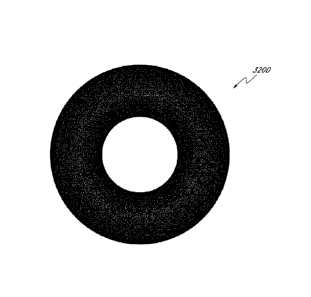
[0018] Figure 6 is a perspective view of one embodiment of a mask.
[0019] Figure 7 is a frontal plan view of an embodiment of a mask with a
hexagon-shaped pinhole like aperture.
[0020] Figure 8 is a frontal plan view of an embodiment of a mask with
an
octagon-shaped pinhole like aperture.
[0021] Figure 9 is a frontal plan view of an embodiment of a mask with
an oval-
shaped pinhole like aperture.
-4-
CA 02770732 2016-11-10
[0022] Figure 10 is a frontal plan view of an embodiment of a mask with
a
pointed oval-shaped pinhole like aperture.
[0023] Figure 11 is a frontal plan view of an embodiment of a mask with
a star-
shaped pinhole like aperture.
[0024] Figure 12 is a frontal plan view of an embodiment of a mask with
a
teardrop-shaped pinhole like aperture spaced above the true center of the
mask.
[0025] Figure 13 is a frontal plan view of an embodiment of a mask with
a
teardrop-shaped pinhole like aperture centered within the mask.
[0026] Figure 14 is a frontal plan view of an embodiment of a mask with
a
teardrop-shaped pinhole like aperture spaced below the true center of the
mask.
[0027] Figure 15 is a frontal plan view of an embodiment of a mask with
a
square-shaped pinhole like aperture.
[0028] Figure 16 is a frontal plan view of an embodiment of a mask with
a
kidney-shaped oval pinhole like aperture.
[0029] Figure 17 is a side view of an embodiment of a mask having
varying
thickness.
[0030] Figure 18 is a side view of another embodiment of a mask having
varying
thickness.
[0031] Figure 19 is a side view of an embodiment of a mask with a gel to
provide
opacity to the lens.
[0032] Figure 20 is frontal plan view of an embodiment of a mask with a
weave
of polymeric fibers.
[0033] Figure 21 is a side view of the mask of Figure 20.
[0034] Figure 22 is a frontal plan view of an embodiment of a mask
having
regions of varying opacity.
[0035] Figure 23 is a side view of the mask of Figure 22.
[0036] Figure 24 is a frontal plan view of an embodiment of a mask that
includes
a centrally located pinhole like aperture and radially extending slots
emanating from the
center to the periphery of the mask.
[0037] Figure 25 is a side view of the mask of Figure 24.
-5-
CA 02770732 2016-11-10
[0038] Figure 26 is a frontal plan view of an embodiment of a mask that
includes
a central pinhole like aperture, surrounded by a plurality of holes radially
spaced from the
pinhole like aperture and slots extending radially spaced from the holes and
extending to the
periphery of the mask.
[0039] Figure 27 is a side view of the mask of Figure 26.
[0040] Figure 28 is a frontal plan view of an embodiment of a mask that
includes
a central pinhole like aperture, a region that includes a plurality of holes
radially spaced from
the aperture, and a region that includes rectangular slots spaced radially
from the holes.
[0041] Figure 29 is a side view of the mask of Figure 28.
[0042] Figure 30 is a frontal plan view of an embodiment of a mask that
includes
a non-circular pinhole like aperture, a first set of slots radially spaced
from the aperture, and a
region that includes a second set of slots extending to the periphery of the
mask and radially
spaced from the first set of slots.
[0043] Figure 31 is a side view of the mask of Figure 30.
[0044] Figure 32 is a frontal plan view of an embodiment of a mask that
includes
a central pinhole like aperture and a plurality of holes radially spaced from
the aperture.
[0045] Figure 33 is a side view of the mask of Figure 32.
[0046] Figure 34 is an embodiment of a mask that includes two semi-
circular
mask portions.
[0047] Figure 35 is an embodiment of a mask including two half-moon
shaped
portions.
[0048] Figure 36 is an embodiment of a mask that includes a half-moon
shaped
region and a centrally-located pinhole like aperture.
[0049] Figure 37 is an enlarged, diagrammatic view of an embodiment of
a mask
that includes particulate structure adapted for selectively controlling light
transmission
through the mask in a low light environment.
[0050] Figure 38 is a view of the mask of Figure 37 in a bright light
environment.
[0051] Figure 39 is an embodiment of a mask that includes a barcode
formed on
the annular region of the mask.
-6-
CA 02770732 2016-11-10
[0052] Figure 40 is another embodiment of a mask that includes
connectors for
securing the mask within the eye.
[0053] Figure 41 is a plan view of an embodiment of a mask made of a
spiraled
fibrous strand.
[0054] Figure 42 is a plan view of the mask of Figure 41 being removed
from the
eye.
[0055] Figure 43 is a top view of another embodiment of a mask
configured to
increase depth of focus.
[0056] Figure 43A is an enlarged view of a portion of the view of Figure
43.
[0057] Figure 44A is a cross-sectional view of the mask of Figure 43A
taken
along the section plane 44--44.
[0058] Figure 44B is a cross-sectional view similar to Figure 44A of
another
embodiment of a mask.
[0059] Figure 44C is a cross-sectional view similar to Figure 44A of
another
embodiment of a mask.
[0060] Figure 45A is a graphical representation of one arrangement of
holes of a
plurality of holes that may be formed on the mask of Figure 43.
[0061] Figure 45B is a graphical representation of another arrangement
of holes
of a plurality of holes that may be formed on the mask of Figure 43.
[0062] Figure 45C is a graphical representation of another arrangement
of holes
of a plurality of holes that may be formed on the mask of Figure 43.
[0063] Figure 46A is an enlarged view similar to that of Figure 43A
showing a
variation of a mask having non-uniform size.
[0064] Figure 46B is an enlarged view similar to that of Figure 43A
showing a
variation of a mask having a non-uniform facet orientation.
[0065] Figure 47 is a top view of another embodiment of a mask having a
hole
region and a peripheral region.
[0066] Figure 48 is a flow chart illustrating one method of aligning a
mask with
an axis of the eye based on observation of an anatomical feature of the eye.
-7-
CA 02770732 2016-11-10
[0067] Figure 49 is a flow chart illustrating one method of screening a
patient for
the use of a mask.
[0068] Figures 50A-50C show a mask, similar to those described herein,
inserted
beneath an epithelium sheet of a cornea.
[0069] Figures 51A-51C show a mask, similar to those described herein,
inserted
beneath a Bowman's membrane of a cornea.
[0070] Figure 52 is a cross-sectional view of an eye illustrating a
treatment of a
patient wherein a flap is opened to place an implant and a location is marked
for placement of
the implant.
[0071] Figure 52A is a partial plan view of the eye of Figure 52 wherein
an
implant has been applied to a corneal flap and positioned with respect to a
ring.
[0072] Figure 53 is a cross-sectional view of an eye illustrating a
treatment of a
patient wherein a pocket is created to place an implant and a location is
marked for placement
of the implant.
[0073] Figure 53A is a partial plan view of the eye of Figure 53 wherein
an
implant has been positioned in a pocket and positioned with respect to a ring.
[0074] Figure 54 is a flow chart illustrating one method for making a
mask from a
composition comprising a highly fluorinated polymer and an opacification
agent.
[0075] Figure 55 is a front view of an embodiment of a mask with a
plurality of
generally randomly distributed holes that have substantially equal size as
described herein.
[0076] Figure 56 is a front view of an embodiment of a mask with larger
holes
near the center of the annulus as described herein.
[0077] Figure 57 is a front view of an embodiment of a mask with a hole
region
that has three sub-regions as described herein.
[0078] Figure 58 is a plot of radial distance from the center of the
aperture as a
function of percentage of epithelial glucose depletion for the masks of
Figures 55 and 56.
DETAILED DESCRIPTION
[0079] This application is directed to corneal inlays (e.g., masks) for
improving
the depth of focus of an eye of a patient and methods and apparatuses for
making such
-8-
CA 02770732 2016-11-10
corneal inlays. The masks generally employ pin-hole vision correction and have
nutrient
transport structures in some embodiments. The masks may be applied to the eye
in any
manner and in any location, e.g., as an implant in the cornea (sometimes
referred to as a
"corneal inlay"). The masks can also be embodied in or combined with lenses
and applied in
other regions of the eye, e.g., as or in combination with contact lenses or
intraocular lenses.
In some applications, discussed further below, the masks are formed of a
stable material, e.g.,
one that can be implanted permanently. Corneal inlays with an opening may also
be used to
treat aniridia.
I. OVERVIEW OF DEPTH OF FOCUS VISION CORRECTION
[0080] As discussed above, mask that has a pinhole aperture may be used
to
improve the depth of focus of a human eye. As discussed above, presbyopia is a
problem of
the human eye that commonly occurs in older human adults wherein the ability
to focus
becomes limited to inadequate range. Figures 1-6 illustrate how presbyopia
interferes with
the normal function of the eye and how a mask with a pinhole aperture
mitigates the problem.
[0081] Figure 1 shows the human eye, and Figure 2 is a side view of the
eye 10.
The eye 10 includes a cornea 12 and an intraocular lens 14 posterior to the
cornea 12. The
cornea 12 is a first focusing element of the eye 10. The intraocular lens 14
is a second
focusing element of the eye 10. The eye 10 also includes a retina 16, which
lines the interior
of the rear surface of the eye 10. The retina 16 includes the receptor cells
which are primarily
responsible for the sense of vision. The retina 16 includes a highly sensitive
region, known
as the macula, where signals are received and transmitted to the visual
centers of the brain via
the optic nerve 18. The retina 16 also includes a point with particularly high
sensitivity 20,
known as the fovea. As discussed in more detail in connection with Figure 8,
the fovea 20 is
slightly offset from the axis of symmetry of the eye 10.
[0082] The eye 10 also includes a ring of pigmented tissue known as the
iris 22.
The iris 22 includes smooth muscle for controlling and regulating the size of
an opening 24 in
the iris 22, which is known as the pupil. An entrance pupil 26 is seen as the
image of the iris
22 viewed through the cornea 12 (See Figure 7). A central point of the
entrance pupil 28 is
illustrated in Figure 7 and will be discussed further below.
-9-
CA 02770732 2016-11-10
[0083] The eye 10 resides in an eye-socket in the skull and is able to
rotate therein
about a center of rotation 30.
[0084] Figure 3 shows the transmission of light through the eye 10 of a
presbyotic
patient. Due to either an aberration in the cornea 12 or the intraocular lens
14, or loss of
muscle control, light rays 32 entering the eye 10 and passing through the
cornea 12 and the
intraocular lens 14 are refracted in such a way that the light rays 32 do not
converge at a
single focal point on the retina 16. Figure 3 illustrates that in a presbyotic
patient, the light
rays 32 often converge at a point behind the retina 16. As a result, the
patient experiences
blurred vision.
[0085] Turning now to Figure 4, there is shown the light transmission
through the
eye 10 to which a mask 34 has been applied. The mask 34 is shown implanted in
the cornea
12 in Figure 4. However, as discussed below, it will be understood that the
mask 34 can be,
in various modes of application, implanted in the cornea 12 (as shown), used
as a contact lens
placed over the cornea 12, incorporated in the intraocular lens 14 (including
the patient's
original lens or an implanted lens), or otherwise positioned on or in the eye
10. In the
illustrated embodiment, the light rays 32 that pass through the mask 34, the
cornea 12, and
the lens 14 converge at a single focal point on the retina 16. The light rays
32 that would not
converge at the single point on retina 16 are blocked by the mask 34. As
discussed below, it
is desirable to position the mask 34 on the eye 10 so that the light rays 32
that pass through
the mask 34 converge at the fovea 20.
[0086] Turning now to Figure 6, there is shown one embodiment of the
mask 34.
A variety of variations of the mask 34 are discussed hereinbelow. Section III
discusses some
materials that can be used to make the mask 34 and any of the variation
thereof discussed
hereinbelow. As seen, the mask 34 preferably includes an annular region 36
surrounding a
pinhole opening or aperture 38 substantially centrally located on the mask 34.
The pinhole
aperture 38 is generally located around a central axis 39, referred to herein
as the optical axis
of the mask 34. The pinhole aperture 38 preferably is in the shape of a
circle. It has been
reported that a circular aperture, such as the aperture 38 may, in some
patients, produce a so-
called "halo effect" where the patient perceives a shimmering image around the
object being
-10-
CA 02770732 2016-11-10
viewed. Accordingly, it may be desirable to provide an aperture 38 in a shape
that
diminishes, reduces, or completely eliminates the so-called "halo effect."
II. MASKS EMPLOYING DEPTH OF FOCUS CORRECTION
[0087] Figures 7-42 illustrate a variety of embodiments of masks that
can improve
the vision of a patient with presbyopia. The masks described in connection
with Figure 7-42
are similar to the mask 34, except as described differently below. Any of the
masks
discussed below, e.g., those shown in Figures 7-42, can be made of the
materials discussed
below in Section III. The mask 34 and any of the masks discussed below can
include a
locator structure, such as is discussed in U.S. Patent Publication No.
2006/0235428, filed
April 14, 2005 with the title "OCULAR INLAY WITH LOCATOR". The masks described
in connection with Figures 7-42 can be used and applied to the eye 10 of a
patient in a similar
fashion to the mask 34. For example, Figure 7 shows an embodiment of a mask
34a that
includes an aperture 38a formed in the shape of a hexagon. Figure 8 shows
another
embodiment of a mask 34b that includes an aperture 38b formed in the shape of
an octagon.
Figure 9 shows another embodiment of a mask 34c that includes an aperture 38c
formed in
the shape of an oval, while Figure 10 shows another embodiment of a mask 34d
that includes
an aperture 38d formed in the shape of a pointed oval. Figure 11 shows another
embodiment
of a mask 34e wherein the aperture 38e is formed in the shape of a star or
starburst.
[0088] Figures 12-14 illustrate further embodiments that have tear-drop
shaped
apertures. Figure 12 shows a mask 34f that has a tear-drop shaped aperture 38f
that is located
above the true center of the mask 34f. Figure 13 shows a mask 34g that has a
tear-drop
shaped aperture 38g that is substantially centered in the mask 34g. Figure 14
shows a mask
34h that has a tear-drop shaped aperture 38h that is below the true center of
the mask 34h.
Figure 12-14 illustrate that the position of aperture can be tailored, e.g.,
centered or off-
center, to provide different effects. For example, an aperture that is located
below the true
center of a mask generally will allow more light to enter the eye because the
upper portion of
the aperture 34 will not be covered by the eyelid of the patient. Conversely,
where the
aperture is located above the true center of the mask, the aperture may be
partially covered by
the eyelid. Thus, the above-center aperture may permit less light to enter the
eye.
-11-
CA 02770732 2016-11-10
[0089] Figure 15 shows an embodiment of a mask 34i that includes an
aperture
38i formed in the shape of a square. Figure 16 shows an embodiment of a mask
34j that has
a kidney-shaped aperture 38j. It will be appreciated that the apertures shown
in Figures 7-16
are merely exemplary of non-circular apertures. Other shapes and arrangements
may also be
provided and are within the scope of the present invention.
[0090] The mask 34 preferably has a constant thickness, as discussed
below.
However, in some embodiments, the thickness of the mask may vary between the
inner
periphery (near the aperture 38) and the outer periphery. Figure 17 shows a
mask 34k that
has a convex profile, i.e., that has a gradually decreasing thickness from the
inner periphery
to the outer periphery. Figure 18 shows a mask 341 that has a concave profile,
i.e., that has a
gradually increasing thickness from the inner periphery to the outer
periphery. Other cross-
sectional profiles are also possible.
[0091] The annular region 36 is at least partially and preferably
completely
opaque. The opacity of the annular region 36 prevents light from being
transmitted through
the mask 32 (as generally shown in Figure 4). Opacity of the annular region 36
may be
achieved in any of several different ways.
[0092] For example, in one embodiment, the material used to make mask 34
may
be naturally opaque. Alternatively, the material used to make the mask 34 may
be
substantially clear, but treated with a dye or other pigmentation agent to
render region 36
substantially or completely opaque. In still another example, the surface of
the mask 34 may
be treated physically or chemically (such as by etching) to alter the
refractive and
transmissive properties of the mask 34 and make it less transmissive to light.
[0093] In still another alternative, the surface of the mask 34 may be
treated with
a particulate deposited thereon. For example, the surface of the mask 34 may
be deposited
with particulate of titanium, gold or carbon to provide opacity to the surface
of the mask 34.
In another alternative, the particulate may be encapsulated within the
interior of the mask 34,
as generally shown in Figure 19. Finally, the mask 34 may be patterned to
provide areas of
varying light transmissivity, as generally shown in Figures 24-33, which are
discussed in
detail below.
-12-
CA 02770732 2016-11-10
[0094] Turning to Figure 20, there is shown a mask 34m formed or made of
a
woven fabric, such as a mesh of polyester fibers. The mesh may be a cross-
hatched mesh of
fibers. The mask 34m includes an annular region 36m surrounding an aperture
38m. The
annular region 36m comprises a plurality of generally regularly positioned
apertures 36m in
the woven fabric allow some light to pass through the mask 34m. The amount of
light
transmitted can be varied and controlled by, for example, moving the fibers
closer together or
farther apart, as desired. Fibers more densely distributed allow less light to
pass through the
annular region 36m. Alternatively, the thickness of fibers can be varied to
allow more or less
light through the openings of the mesh. Making the fiber strands larger
results in the
openings being smaller.
[00951 Figure 22 shows an embodiment of a mask 34n that includes an
annular
region 36n that has sub-regions with different opacities. The opacity of the
annular region
36n may gradually and progressively increase or decrease, as desired. Figure
22 shows one
embodiment where a first area 42 closest to an aperture 38n has an opacity of
approximately
43%. In this embodiment, a second area 44, which is outlying with respect to
the first area
42, has a greater opacity, such as 70%. In this embodiment, a third area 46,
which is outlying
with respect to the second area 42, has an opacity of between 85 to 100%. The
graduated
opacity of the type described above and shown in Figure 22 is achieved in one
embodiment
by, for example, providing different degrees of pigmentation to the areas 42,
44 and 46 of the
mask 34n. In another embodiment, light blocking materials of the type
described above in
variable degrees may be selectively deposited on the surface of a mask to
achieve a graduated
opacity.
[0096] In another embodiment, the mask may be formed from co-extruded
rods
made of material having different light transmissive properties. The co-
extruded rod may
then be sliced to provide disks for a plurality of masks, such as those
described herein.
[0097] Figures 24-33 shows examples of masks that have been modified to
provide regions of differing opacity. For example, Figure 24 shows a mask 34o
that includes
an aperture 38o and a plurality of cutouts 48 in the pattern of radial spokes
extending from
near the aperture 38o to an outer periphery 50 of the mask 34o. Figure 24
shows that the
cutouts 48 are much more densely distributed about a circumference of the mask
near
-13-
CA 02770732 2016-11-10
aperture 38o than are the cutouts 48 about a circumference of the mask near
the outer
periphery 50. Accordingly, more light passes through the mask 34o nearer
aperture 38o than
near the periphery 50. The change in light transmission through the mask 34o
is gradual.
[0098] Figures 26-27 show another embodiment of a mask 34p. The mask
34p
includes an aperture 38p and a plurality of circular cutouts 49p, and a
plurality of cutouts 51p.
The circular cutouts 49p are located proximate the aperture 38p. The cutouts
51p are located
between the circular cutouts 49p and the periphery 50p. The density of the
circular cutouts
49p generally decreases from the near the aperture 38p toward the periphery
50p. The
periphery 50p of the mask 34p is scalloped by the presence of the cutouts 51,
which extend
inward from the periphery 50p, to allow some light to pass through the mask at
the periphery
50p.
[0099] Figures 28-29 shows another embodiment similar to that of
Figures 26-27
wherein a mask 34q includes a plurality of circular cutouts 49q and a
plurality of cutouts 51q.
The cutouts 51q are disposed along the outside periphery 50q of the mask 34q,
but not so as
to provide a scalloped periphery.
[0100] Figures 30 and 31 illustrate an embodiment of a mask 34r that
includes an
annular region 36r that is patterned and an aperture 38r that is non-circular.
As shown in
Figure 30, the aperture 38r is in the shape of a starburst. Surrounding the
aperture 38r is a
series of cutouts 51r that are more densely spaced toward the aperture 38r.
The mask 34r
includes an outer periphery 50r that is scalloped to provide additional light
transmission at
the outer periphery 50r.
[0101] Figures 32 and 33 show another embodiment of a mask 34s that
includes
an annular region 36s and an aperture 38s. The annular region 36s is located
between an
outer periphery 50s of the mask 34s and the aperture 38s. The annular region
36s is
patterned. In particular, a plurality of circular openings 56s is distributed
over the annular
region 36s of the mask 34s. It will be appreciated that the density of the
openings 56s is
greater near the aperture 38s than near the periphery 50s of the mask 34s. As
with the
examples described above, this results in a gradual increase in the opacity of
the mask 34s
from aperture 38s to periphery 50s.
-14-
CA 02770732 2016-11-10
[0102] Figures 34-36 show further embodiments. In particular, Figure 34
shows a
mask 34t that includes a first mask portion 58t and a second mask portion 60t.
The mask
portions 58t, 60t are generally "C-shaped." As shown in Figure 34, the mask
portions 58t,
60t are implanted or inserted such that the mask portions 58t, 60t define a
pinhole or aperture
38t.
[0103] Figure 35 shows another embodiment wherein a mask 34u includes
two
mask portions 58u, 43u. Each mask portion 58u, 43u is in the shape of a half-
moon and is
configured to be implanted or inserted in such a way that the two halves
define a central gap
or opening 45u, which permits light to pass therethrough. Although opening 45u
is not a
circular pinhole, the mask portions 58u, 43u in combination with the eyelid
(shown as dashed
line 47) of the patient provide a comparable pinhole effect.
[0104] Figure 36 shows another embodiment of a mask 34v that includes an
aperture 38v and that is in the shape of a half-moon. As discussed in more
detail below, the
mask 34v may be implanted or inserted into a lower portion of the cornea 12
where, as
described above, the combination of the mask 34v and the eyelid 45 provides
the pinhole
effect.
[0105] Other embodiments employ different ways of controlling the light
transmissivity through a mask. For example, the mask may be a gel-filled disk,
as shown in
Figure 19. The gel may be a hydrogel or collagen, or other suitable material
that is
biocompatible with the mask material and can be introduced into the interior
of the mask.
The gel within the mask may include particulate 53 suspended within the gel.
Examples of
suitable particulate are gold, titanium, and carbon particulate, which, as
discussed above, may
alternatively be deposited on the surface of the mask.
[0106] The material of the mask 34 may be any biocompatible polymeric
material. Where a gel is used, the material is suitable for holding a gel.
Examples of suitable
materials for the mask 34 include the preferred polymethylmethacrylate or
other suitable
polymers, such as polycarbonates and the like. Of course, as indicated above,
for non-gel-
filled materials, a preferred material may be a fibrous material, such as a
Dacron mesh.
[0107] The mask 34 may also be made to include a medicinal fluid or
material,
such as an antibiotic or other wound healing modulator that can be selectively
released after
-15-
CA 02770732 2016-11-10
application, insertion, or implantation of the mask 34 into the eye of the
patient. Release of
an antibiotic or other wound healing modulator after application, insertion,
or implantation
provides faster and/or improved healing of the incision. The mask 34 may also
be coated
with other desired drugs or antibiotics. For example, it is known that
cholesterol deposits can
build up on the eye. Accordingly, the mask 34 may be provided with a
releasable cholesterol
deterring drug. The drug may be coated on the surface of the mask 34 or, in an
alternative
embodiment, incorporated into the polymeric material (such as PMMA) from which
the mask
34 is formed.
[0108] Figures 37 and 38 illustrate one embodiment where a mask 34w
comprises
a plurality of nanites 68. "Nanites" are small particulate structures that
have been adapted to
selectively transmit or block light entering the eye of the patient. The
particles may be of a
very small size typical of the particles used in nanotechnology applications.
The nanites 68
are suspended in the gel or otherwise inserted into the interior of the mask
34w, as generally
shown in Figures 37 and 38. The nanites 68 can be preprogrammed to respond to
different
light environments.
[0109] Thus, as shown in Figure 37, in a high light environment, the
nanites 68
turn and position themselves to substantially and selectively block some of
the light from
entering the eye. However, in a low light environment where it is desirable
for more light to
enter the eye, nanites may respond by turning or be otherwise positioned to
allow more light
to enter the eye, as shown in Figure 38.
[0110] Nano-devices or nanites are crystalline structures grown in
laboratories.
The nanites may be treated such that they are receptive to different stimuli
such as light. In
accordance with one aspect of the present invention, the nanites can be
imparted with energy
where, in response to a low light and high light environments, they rotate in
the manner
described above and generally shown in Figure 38.
[0111] Nanoscale devices and systems and their fabrication are
described in
Smith et al., "Nanofabrication," Physics Today, February 1990, pp. 24-30 and
in Craighead,
"Nanoelectromechanical Systems," Science, November 24, 2000, Vol. 290, pp.
1502-1505.
Tailoring the properties of small-sized particles for optical applications is
disclosed in Chen
-16-
CA 02770732 2016-11-10
et al. "Diffractive Phase Elements Based on Two-Dimensional Artificial
Dielectrics," Optics
Letters, January 15, 1995, Vol.. 20, No. 2, pp. 121-123.
[0112] Masks 34 made in accordance with the present invention may be
further
modified to include other properties. Figure 39 shows one embodiment of a mask
34x that
includes a bar code 66 or other printed indicia.
[0113] The masks described herein may be incorporated into the eye of a
patient
in different ways. For example, as discussed in more detail below in
connection with Figure
49, the mask 34 may be provided as a contact lens placed on the surface of the
eyeball 10.
Alternatively, the mask 34 may be incorporated in an artificial intraocular
lens designed to
replace the original lens 14 of the patient. Preferably, however, the mask 34
is provided as a
corneal implant or inlay, where it is physically inserted between the layers
of the cornea 12.
[0114] When used as a corneal implant, layers of the cornea 12 are
peeled away to
allow insertion of the mask 34. Typically, the optical surgeon (using a laser)
cuts away and
peels away a flap of the overlying corneal epithelium. The mask 34 is then
inserted and the
flap is placed back in its original position where, over time, it grows back
and seals the
eyeball. In some embodiments, the mask 34 is attached or fixed to the eye 10
by support
strands 72 and 74 shown in Figure 40 and generally described in U.S. Patent
No. 4,976,732.
[0115] In certain circumstances, to accommodate the mask 34, the surgeon
may
be required to remove additional corneal tissue. Thus, in one embodiment, the
surgeon may
use a laser to peel away additional layers of the cornea 12 to provide a
pocket that will
accommodate the mask 34. Application of the mask 34 to the cornea 12 of the
eye 10 of a
patient is described in greater detail in connection with Figures 50A ¨ 51C.
[0116] Removal of the mask 34 may be achieved by simply making an
additional
incision in the cornea 12, lifting the flap and removing the mask 34.
Alternatively, ablation
techniques may be used to completely remove the mask 34.
[0117] Figures 41 and 42 illustrate another embodiment, of a mask 34y
that
includes a coiled strand 80 of a fibrous or other material. Strand 80 is
coiled over itself to
form the mask 34y, which may therefore be described as a spiral-like mask.
This
arrangement provides a pinhole or aperture 38y substantially in the center of
the mask 34y.
The mask 34y can be removed by a technician or surgeon who grasps the strand
80 with
-17-
CA 02770732 2016-11-10
tweezers 82 through an opening made in a flap of the corneal 12. Figure 42
shows this
removal technique.
[0118] Further mask details are disclosed in U.S. Patent No. 4,976,732,
issued
December 11, 1990 and in U.S. Patent Application No. 10/854,033, filed May 26,
2004
(issued as US 7,628,810, 8 December 2009) .
III. PREFERRED UV-RESISTANT POLYMERIC MASK MATERIALS
[0119] Because the mask has a very high surface to volume ratio and is
exposed
to a great deal of sunlight following implantation, the mask preferably
comprises a material
which has good resistance to degradation, including from exposure to
ultraviolet (UV) or
other wavelengths of light. Polymers including a UV absorbing component,
including those
comprising UV absorbing additives or made with UV absorbing monomers
(including co-
monomers), may be used in forming masks as disclosed herein which are
resistant to
degradation by UV radiation. Examples of such polymers include, but are not
limited to,
those described in U.S. Patent Nos. 4,985,559 and 4,528,311. In a preferred
embodiment, the
mask comprises a material which itself is resistant to degradation by UV
radiation. In one
embodiment, the mask comprises a polymeric material which is substantially
reflective of or
transparent to UV radiation.
[0120] Alternatively, the mask may include a component which imparts a
degradation resistive effect, or may be provided with a coating, preferably at
least on the
anterior surface, which imparts degradation resistance. Such components may be
included,
for example, by blending one or more degradation resistant polymers with one
or more other
polymers. Such blends may also comprise additives which provide desirable
properties, such
as UV absorbing materials. In one embodiment, blends preferably comprise a
total of about
1-20 wt.%, including about 1-10 wt.%, 5-15 wt.%, and 10-20 wt.% of one or more
degradation resistant polymers. In another embodiment, blends preferably
comprise a total of
about 80-100 wt.%, including about 80-90 wt.%, 85-95 wt.%, and 90-100 wt.% of
one or
more degradation resistant polymers. In another embodiment, the blend has more
equivalent
proportions of materials, comprising a total of about 40-60 wt.%, including
about 50-60
wt.%, and 40-50 wt.% of one or more degradation resistant polymers. Masks may
also
-18-
CA 02770732 2016-11-10
include blends of different types of degradation resistant polymers, including
those blends
comprising one or more generally UV transparent or reflective polymers with
one or more
polymers incorporating UV absorption additives or monomers. These blends
include those
having a total of about 1-20 wt.%, including about 1-10 wt.%, 5-15 wt.%, and
10-20 wt.% of
one or more generally UV transparent polymers, a total of about 80-100 wt.%,
including
about 80-90 wt.%, 85-95 wt.%, and 90-100 wt.% of one or more generally UV
transparent
polymers, and a total of about 40-60 wt.%, including about 50-60 wt.%, and 40-
50 wt.% of
one or more generally UV transparent polymers. The polymer or polymer blend
may be
mixed with other materials as discussed below, including, but not limited to,
opacification
agents, polyanionic compounds and/or wound healing modulator compounds. When
mixed
with these other materials, the amount of polymer or polymer blend in the
material which
makes up the mask is preferably about 50%-99% by weight, including about 60%-
90% by
weight, about 65-85% by weight, about 70-80% by weight, and about 90-99% by
weight.
[0121]
Preferred degradation resistant polymers include halogenated polymers.
Preferred halogenated polymers include fluorinated polymers, that is, polymers
having at
least one carbon-fluorine bond, including highly fluorinated polymers. The
term "highly
fluorinated" as it is used herein, is a broad term used in its ordinary sense,
and includes
polymers having at least one carbon-fluorine bond (C-F bond) where the number
of C-F
bonds equals or exceeds the number of carbon-hydrogen bonds (C-H bonds).
Highly
fluorinated materials also include perfluorinated or fully fluorinated
materials, materials
which include other halogen substituents such as chlorine, and materials which
include
oxygen- or nitrogen-containing functional groups. For polymeric materials, the
number of
bonds may be counted by referring to the monomer(s) or repeating units which
form the
polymer, and in the case of a copolymer, by the relative amounts of each
monomer (on a
molar basis).
[0122]
Preferred highly fluorinated polymers include, but are not limited to,
polytetrafluoroethylene (PFTE or Teflon ), polyvinylidene fluoride (PVDF or
Kynar ), poly-
1,1,2-trifluoroethylene, and perfluoroalkoxyethylene (PFA). Other
highly fluorinated
polymers include, but are not limited to, homopolymers and copolymers
including one or
more of the following monomer units: tetrafluoroethylene -(CF2-CF2)-;
vinylidene fluoride -
-19-
CA 02770732 2016-11-10
(CF2-CH2)-; 1,1,2-trifluoroethylene -(CF2-CHF)-; hexafluoropropene -(CF(CF3)-
CF2)-; vinyl
fluoride -(CH2-CHF)- (homopolymer is not "highly fluorinated"); oxygen-
containing
monomers such as -(0-CF2)-, -(0-CF2-CF2)-, -(0-CF(CF3)-CF2)-; chlorine-
containing
monomers such as -(CF2-CFC1)-. Other fluorinated polymers, such as fluorinated
polyimide
and fluorinated acrylates, having sufficient degrees of fluorination are also
contemplated as
highly fluorinated polymers for use in masks according to preferred
embodiments. The
homopolymers and copolymers described herein are available commercially and/or
methods
for their preparation from commercially available materials are widely
published and known
to those in the polymer arts.
[0123] Although highly fluorinated polymers are preferred, polymers
having one
or more carbon-fluorine bonds but not falling within the definition of "highly
fluorinated"
polymers as discussed above, may also be used. Such polymers include co-
polymers formed
from one or more of the monomers in the preceding paragraph with ethylene,
vinyl fluoride
or other monomer to form a polymeric material having a greater number of C-H
bonds than
C-F bonds. Other fluorinated polymers, such as fluorinated polyimide, may also
be used.
Other materials that could be used in some applications, alone or in
combination with a
fluorinated or a highly fluorinated polymer, are described in U.S. Patent No.
4,985,559 and in
U.S. Patent No. 4,538,311.
[0124] The preceding definition of highly fluorinated is best
illustrated by means
of a few examples. One preferred UV-resistant polymeric material is
polyvinylidene fluoride
(PVDF), having a structure represented by the formula: -(CF2-CH2)n-. Each
repeating unit
has two C-H bonds, and two C-F bonds. Because the number of C-F bonds equals
or exceeds
the number of C-H bonds, PVDF homopolymer is a "highly fluorinated" polymer.
Another
material is a tetrafluoroethylene/vinyl fluoride copolymer formed from these
two monomers
in a 2:1 molar ratio. Regardless of whether the copolymer formed is block,
random or any
other arrangement, from the 2:1 tetrafluoroethylene:vinyl fluoride composition
one can
presume a "repeating unit" comprising two tetrafluoroethylene units, each
having four C-F
bonds, and one vinyl fluoride unit having three C-H bonds and one C-F bond.
The total
bonds for two tetrafluoroethylenes and one vinyl fluoride are nine C-F bonds,
and three C-H
-20-
CA 02770732 2016-11-10
bonds. Because the number of C-F bonds equals or exceeds the number of C-H
bonds, this
copolymer is considered highly fluorinated.
[0125] Certain highly fluorinated polymers, such as PVDF, have one or
more
desirable characteristics, such as being relatively chemically inert and
having a relatively high
UV transparency as compared to their non-fluorinated or less highly
fluorinated counterpart
polymers. Although the applicant does not intend to be bound by theory, it is
postulated that
the electronegativity of fluorine may be responsible for many of the desirable
properties of
the materials having relatively large numbers of C-F bonds.
[0126] In preferred embodiments, at least a portion of the highly
fluorinated
polymer material forming the mask comprises an opacification agent which
imparts a desired
degree of opacity. In one embodiment, the opacification agent provides
sufficient opacity to
produce the depth of field improvements described herein, e.g., in combination
with a
transmissive aperture. In one embodiment, the opacification agent renders the
material
opaque. In another embodiment, the opacification agent prevents transmission
of about 90
percent or more of incident light. In another embodiment, the opacification
agent renders the
material opaque. In another embodiment, the opacification agent prevents
transmission of
about 80 percent or more of incident light. Preferred opacification agents
include, but are not
limited to organic dyes and/or pigments, preferably black ones, such as azo
dyes, hematoxylin
black, and Sudan black; inorganic dyes and/or pigments, including metal oxides
such as iron
oxide black and ilminite, silicon carbide and carbon (e.g. carbon black,
submicron powdered
carbon). The foregoing materials may be used alone or in combination with one
or more
other materials. The opacification agent may be applied to one or more
surfaces of the mask
on all or some of the surface, or it may be mixed or combined with the
polymeric material
(e.g. blended during the polymer melt phase). Although any of the foregoing
materials may
be used, carbon has been found to be especially useful in that it does not
fade over time as do
many organic dyes, and that it also aids the UV stability of the material by
absorbing UV
radiation In one embodiments, carbon may be mixed with polyvinylidene fluoride
(PVDF) or
other polymer composition comprising highly fluorinated polymer such that the
carbon
comprises about 2% to about 20% by weight of the resulting composition,
including about
-21-
CA 02770732 2016-11-10
10% to about 15% by weight, including about 12%, about 13%, and about 14% by
weight of
the resulting composition.
[0127] Some opacification agents, such pigments, which are added to
blacken,
darken or opacify portions of the mask may cause the mask to absorb incident
radiation to a
greater degree than mask material not including such agents. Because the
matrix polymer
that carries or includes the pigments may be subject to degradation from the
absorbed
radiation, it is preferred that the mask, which is thin and has a high surface
area making it
vulnerable to environmental degradation, be made of a material which is itself
resistant to
degradation such as from UV radiation, or that it be generally transparent to
or non-absorbing
of UV radiation. Use of a highly UV resistant and degradation resistant
material, such as
PVDF, which is highly transparent to UV radiation, allows for greater
flexibility in choice of
opacification agent because possible damage to the polymer caused by selection
of a
particular opacification agent is greatly reduced.
[0128] A number of variations of the foregoing embodiments of
degradation
resistant constructions are contemplated. In one variation, a mask is made
almost exclusively
of a material that is not subject to UV degradation. For example, the mask can
be made of a
metal, a highly fluorinated polymer, or another similar material. Construction
of the mask
with metal is discussed in more detail in U.S. application 11/000,562 filed
December 1, 2004
(issued as 7,491,350, 17 February 2009) and entitled "Method of Making an
Ocular Implant"
and also in U.S. application 11/107,359 filed April 14, 2005 (publication US
2006-0113054
A1) with the title "Method of Making an Ocular Implant". As used in this
context,
"exclusively" is a broad term that allows for the presence of some non-
functional materials
(e.g., impurities) and for an opacification agent, as discussed above. In
other embodiments,
the mask can include a combination of materials. For example, in one
variation, the mask is
formed primarily of any implantable material and is coated with a UV resistant
material. In
another variation, the mask includes one or more UV degradation inhibitors
and/or one or
more UV degradation resistant polymers in sufficient concentration such that
the mask under
normal use conditions will maintain sufficient functionality in terms of
degradation to remain
medically effective for at least about 5 years, preferably at least about 10
years, and in certain
implementations at least about 20 years.
-22-
CA 02770732 2016-11-10
[0129] Figure
54 is a flow chart illustrating one method for making a mask from a
composition comprising a highly fluorinated polymer and an opacification
agent. At step
2000, a liquid form of a polymer is created by dissolving polyvinylidene
fluoride (PVDF)
pellets into a solvent such as Dimethyl Acetamide (DMAC or DMA) using heat
until the
PVDF has completely dissolved. In one embodiment, the solution may be mixed
for a
minimum of 12 hours to ensure that the PVDF has completely dissolved. At step
2200, the
PVDF/DMAC solution is mixed with an opacification agent, such as carbon black,
using a
high speed shear mixer. In one embodiment, the carbon black comprises 13% by
weight of
the resulting composition while the PVDF comprises 87% by weight of the
resulting
composition. At step 2300, the PVDF/carbon black solution is milled in a high
speed mill,
for example an Eiger high speed mill, to break up any large carbon
agglomerates in the
solution. The PVDF/carbon black solution may be run through the mill a second
time to
further break up any carbon agglomerates. At step 2400, the resulting solution
is applied to a
silicone wafer to create a polymer film on the silicone disk. Here,
approximately 55g of the
PVDF/carbon black solution is poured into a dispensing barrel for application
on a silicone
wafer. The silicone disk is placed on the spinner of a spin casting machine
and the
dispensing barrel is used to apply a bead of PVDF/carbon black solution to the
silicone wafer
in a circular pattern, leaving the center 1" diameter of the disk empty. The
spinner cycle is
actuated to disperse the PVDF/carbon black solution over the disk, forming a
uniform 10
micron thick film. The coated silicone disk is then placed on a hot-plate to
evaporate the
DMAC. At step 2500, the coated silicon e wafer is placed under an Eximer
laser. A laser
cutting mask is mounted in the laser and the laser is actuated. Using the
laser cutting mask,
approximately 150 corneal mask patterns are laser machined into the
PVDF/carbon black
film. The corneal mask patterns are arranged such that the material extending
approximately
5mm from the edge of the silicon disk is not used. During the laser machining,
the silicone
disk may be bathed in Nitrogen gas in order to cool the surface. At step 2600,
the laser
machined masks are removed from the silicone disk using a razor blade and
placed into the
bottom half of a convex Teflon forming mold. The top half of the Teflon
forming mold is
placed on top of the mask and the molds placed in an oven at about 160 C. At
step 2700, the
molds are heated and baked to cure the masks. The molds are allowed to bake
for
-23-
CA 02770732 2016-11-10
approximately two hours at approximately 160 C. After two hours the oven
temperature is
reduced to about 30 C and the masks are baked for approximately two hours or
until the oven
temperature has dropped to below around 40 C.
IV. ADDITIVES TO REDUCE CORNEAL DEPOSITS AND/OR PROMOTE
PROPER HEALING
[0130] In some
circumstances, corneal implants are associated with deposits on
the cornea. Loading of one or more polyanionic compounds into the polymeric
material of a
corneal implant may reduce and/or substantially eliminate deposits on the
cornea, possibly by
attracting and/or retaining growth factors.
[0131] In a
preferred embodiment the one or more polyanionic compounds
include carbohydrates, proteins, natural proteoglycans, and/or the
glycosaminoglycan
moieties of proteoglycans, as well as derivatives (such as sulfated
derivatives) and salts of
compounds such as those in the aforementioned categories.
Preferred polyanionic
compounds include one or more of dermatan sulfate, chondroitin sulfate,
keratan sulfate,
heparan sulfate, heparin, dextran sulfate, hyaluronic acid, pentosan
polysulfate, xanthan,
carrageenan, fibronectin, laminin, chondronectin, vitronectin, poly L-lysine
salts, and anionic,
preferably sulfated, carbohydrates such as alginate may also be used, as well
as salts and
derivatives of the listed compounds. Examples of preferred anionic compounds
and
combinations of polyanionic compounds include keratan sulfate/chrondroitin
sulfate-
proteoglycan, dermatan sulfate proteoglycan, and dextran sulfate.
[0132] In one
embodiment, a polyanionic compound comprises acidic sulfate
moieties and the sulfur content is greater than about 5% by weight, preferably
greater than
about 10% by weight. In an even more preferred embodiment, the average
molecular weight
of a polyanionic compound is about 40,000 to 500,000 Daltons.
[0133] In a
preferred embodiment, the total weight of the one or more polyanionic
compounds in the loaded polymeric material is about 0.1% by weight to about
50% by
weight, including about 5% by weight to about 20% by weight, about 12% by
weight to about
17% by weight, about 0.5% by weight to about 4% by weight, and about 5% by
weight to
about 15% by weight. It should be noted that the percentages recited herein in
relation to
-24-
CA 02770732 2016-11-10
polyanionic compounds, opacification agents and wound healing modulator
compounds are
percent by weight with 100% being the total weight of the entire mask
composition including
all additives.
[0134] In one embodiment, the body of the mask is formed from a
polymeric
material having one or more polyanionic compounds loaded therein. Loading of a
polyanionic compound is performed by mixing the polyanionic compound with the
resin and
any other additives of the polymeric material prior to molding or casting of
the body of the
mask. Although some of a polyanionic compound that is loaded into the
polymeric material
may be on the surface of the mask, loading is to be distinguished from coating
in that a
coated material would not have polyanionic material throughout the bulk of the
mask.
[0135] The loaded polymeric material is preferably made by suspending or
dissolving polymer, one or more polyanionic compounds and any other additives
(such as
wound healing modulators, as described below) in a solvent or solvent system,
and then
casting a film whereby the solvent or solvent system is removed such as by
evaporation.
Preferred casting methods include spin casting and other methods, including
those known in
the art, which can form a thin material of relatively even thickness. Although
other methods
of making thin substrates, such as extrusion, may be used, solvent casting is
generally
preferred because it does not need to be done at high temperatures that may
cause degradation
of some polyanionic compounds. The polymer, polyanionic compound, and/or other
additives may be ground or milled, such as by ball milling, to reduce the
particle size of the
material prior to suspending, dissolving or melting as part of making the
mask.
[0136] In methods using solvent casting, preferred solvents include
those which
are capable of dissolving the polymeric material, polyanionic compounds,
and/or other
additives. A suitable solvent or solvent system (i.e. combination of two or
more solvents)
may be chosen by one skilled in the art based upon known solubilities for a
given polymeric
material and/or routine experimentation based upon chemical principles. In
solvent casting
methods, the temperature of the solvent or solution should be no higher than
the boiling point
of the solvent or solvent system, and is preferably about 10 C to about 70 C.
During or after
casting of the solution to form a film, the temperature may be elevated,
including above the
boiling point.
-25-
CA 02770732 2016-11-10
[0137] In one embodiment, a mask, such as an inlay, comprising PVDF,
dextran
sulfate, and carbon was made by spin casting. 100 grams of PVDC (about 71% by
weight) in
the form of pellets was dissolved in 400 grams of dimethylacetamide. 17 grams
of carbon
(about 12% by weight) and 24 grams of dextran sulfate (about 17% by weight)
are ball milled
to reduce particle size and then added to the PVDF/DMA solution. The
percentages by
weight are the percentages of the solids portion, that is the portion that is
not the solvent. The
solution was at room temperature (approximately 17 C to about 25 C). The
solution was
then spin cast to form a film.
[0138] In one embodiment, the device includes a wound healing modulator.
When present, the wound healing modulator is on at least one surface or it may
be loaded
into the polymeric material. A wound healing modulator is defined as a
compound that
assists in proper healing of a wound, such as by increasing the rate of
healing, decreasing
inflammation, moderating or suppressing immune response, decreasing scarring,
decreasing
cell proliferation, reducing infection, encouraging transdifferentiation of
keratocytes into cells
that lay down collagen, and the like. Wound healing modulators include,
without limitation,
antibiotics, antineoplastics including antimitotics, antimetabolics and
antibiotic types, anti-
inflammatories, immunosupressants, and antifungals. Preferred compounds
include, but are
not limited to, fluorouracil, mitomycin C, paclitaxel, NSAIDs (e.g. ibuprofen,
naproxen,
flurbiprofen, carprofen, suprofen, ketoprofen), and cyclosporins. Other
preferred compounds
include proteoglycans, glycosaminoglycans, and salts and derivatives thereof,
as well as other
carbohydrates and/or proteins, including those disclosed above.
[01391 A wound healing modulator may be included in the mask by loading
it into
the polymeric material as discussed above with respect to the polyanionic
compounds. It may
also be included by binding it to one or more surfaces of the device. The
"binding" of the
wound healing modulator to the device may occur by phenomena that do not
generally
involve chemical bonds, including adsorption, hydrogen bonding, van der Waals
forces,
electrostatic attraction, ionic bonding, and the like, or it may occur by
phenomena that do
include chemical bonds. In a preferred embodiment, the total weight of the one
or more
wound healing modulator compounds in the loaded polymeric material is about
0.1% by
weight to about 50% by weight, including about 5% by weight to about 20% by
weight, about
-26-
CA 02770732 2016-11-10
12% by weight to about 17% by weight, about 0.5% by weight to about 4% by
weight, and
about 5% by weight to about 15% by weight.
[0140] In one embodiment, carbon, gold or other material on a surface of
the
mask acts as an adsorbent or otherwise participates in the binding of one or
more wound
healing modulators to the implant. The material on the surface of the mask
that participates
in binding the wound healing modulator may be part of the bulk material of the
implant
(distributed throughout the implant or which migrates to the surface during
and/or following
formation of the implant) and/or deposited on a surface of the mask, such as
an opacification
agent as described elsewhere infra. The implant is then exposed to one or more
wound
healing modulators, such as by dipping in a solution (including dispersions
and emulsions)
comprising at least one wound healing modulator, to allow wound healing
modulator(s) to
bind to the implant. The solvent used to assist in applying and binding the
wound healing
modulator to the implant is preferably biocompatible, does not leave a harmful
residue,
and/or does not cause dissolution or swelling of the polymeric material of the
mask. If more
than one wound healing modulator is used, binding may be performed by dipping
in a single
solution containing all desired wound healing modulators or by dipping the
implant in two or
more successive solutions, each of which contains one or more of the desired
wound healing
modulators. The process of binding wound healing modulator to the implant may
be done at
any time. In one embodiment, at least some of the wound healing modulator is
bound to the
implant as part of the manufacturing process. In another embodiment, a medical
practitioner,
such as an ophthalmologist, binds at least some of the wound healing modulator
to the
implant just prior to implantation.
[0141] In alternate embodiments, one or more wound healing modulators
are
bound to the implant using any suitable method for binding drugs or other
useful compounds
to implants and medical devices and/or using methods for making drug delivery
devices
which deliver a drug locally in the area of implantation or placement over a
period of time.
V. MASKS CONFIGURED TO REDUCE VISIBILE DIFFRACTION PATTERNS
[0142] Many of the foregoing masks can be used to improve the depth of
focus of
a patient. Various additional mask embodiments are discussed below. Some of
the
-27-
CA 02770732 2016-11-10
embodiments described below include nutrient transport structures that are
configured to
enhance or maintain nutrient flow between adjacent tissues by facilitating
transport of
nutrients across the mask. The nutrient transport structures of some of the
embodiments
described below are configured to at least substantially prevent nutrient
depletion in adjacent
tissues. The nutrient transport structures can decrease negative effects due
to the presence of
the mask in adjacent corneal layers when the mask is implanted in the cornea,
increasing the
longevity of the masks. The inventors have discovered that certain
arrangements of nutrient
transport structures generate diffraction patterns that interfere with the
vision improving
effect of the masks described herein. Accordingly, certain masks are described
herein that
include nutrient transport structures that do not generate diffraction
patterns or otherwise
interfere with the vision enhancing effects of the mask embodiments.
[0143] Figures 43-44 show one embodiment of a mask 100 configured to
increase
depth of focus of an eye of a patient suffering from presbyopia. The mask 100
is similar to
the masks hereinbefore described, except as described differently below. The
mask 100 can
be made of the materials discussed herein, including those discussed in
Section III. Also, the
mask 100 can be formed by any suitable process, such as those discussed below
in connection
with Figures 48a-48d with variations of such processes. The mask 100 is
configured to be
applied to an eye of a patient, e.g., by being implanted in the cornea of the
patient. The mask
100 may be implanted within the cornea in any suitable manner, such as those
discussed
above in connection with Figures 50A-51C.
[0144] In one embodiment, the mask 100 includes a body 104 that has an
anterior
surface 108 and a posterior surface 112. In one embodiment, the body 104 is
capable of
substantially maintaining natural nutrient flow between the first corneal
layer and the second
corneal layer. In one embodiment, the material is selected to maintain at
least about ninety-
six percent of the natural flow of at least one nutrient (e.g., glucose)
between a first corneal
layer (e.g., the layer 1210) and a second corneal layer (e.g., the layer
1220). The body 104
may be formed of any suitable material, including at least one of an open cell
foam material,
an expanded solid material, and a substantially opaque material. In one
embodiment, the
material used to form the body 104 has relatively high water content.
-28-
CA 02770732 2016-11-10
[01451 In one embodiment, the mask 100 includes and a nutrient
transport
structure 116. The nutrient transport structure 116 may comprise a plurality
of holes 120.
The holes 120 are shown on only a portion of the mask 100, but the holes 120
preferably are
located throughout the body 104 in one embodiment. In one embodiment, the
holes 120 are
arranged in a hex pattern, which is illustrated by a plurality of locations
120' in Figure 45A.
As discussed below, a plurality of locations may be defined and later used in
the later
formation of a plurality of holes 120 on the mask 100. The mask 100 has an
outer periphery
124 that defines an outer edge of the body 104. In some embodiments, the mask
100 includes
an aperture 128 at least partially surrounded by the outer periphery 124 and a
non-
transmissive portion 132 located between the outer periphery 124 and the
aperture 128.
[0146] Preferably the mask 100 is symmetrical, e.g., symmetrical about
a mask
axis 136. In one embodiment, the outer periphery 124 of the mask 100 is
circular. The
masks in general have has a diameter within the range of from about 3 mm to
about 8 mm,
often within the range of from about 3.5 mm to about 6 mm, and less than about
6 mm in one
embodiment. In another embodiment, the mask is circular and has a diameter in
the range of
4 to 6 mm. In another embodiment, the mask 100 is circular and has a diameter
of less than 4
mm. The outer periphery 124 has a diameter of about 3.8 mm in another
embodiment. In
some embodiments, masks that are asymmetrical or that are not symmetrical
about a mask
axis provide benefits, such as enabling a mask to be located or maintained in
a selected
position with respect to the anatomy of the eye.
[0147] The body 104 of the mask 100 may be configured to coupled with a
particular anatomical region of the eye. The body 104 of the mask 100 may be
configured to
conform to the native anatomy of the region of the eye in which it is to be
applied. For
example, where the mask 100 is to be coupled with an ocular structure that has
curvature, the
body 104 may be provided with an amount of curvature along the mask axis 136
that
corresponds to the anatomical curvature. For example, one environment in which
the mask
100 may be deployed is within the cornea of the eye of a patient. The cornea
has an amount
of curvature that varies from person to person about a substantially constant
mean value
within an identifiable group, e.g., adults. When applying the mask 100 within
the cornea, at
least one of the anterior and posterior surfaces 108, 112 of the mask 100 may
be provided
-29-
CA 02770732 2016-11-10
with an amount of curvature corresponding to that of the layers of the cornea
between which
the mask 100 is applied.
[0148] In some embodiments, the mask 100 has a desired amount of optical
power. Optical power may be provided by configuring the at least one of the
anterior and
posterior surfaces 108, 112 with curvature. In one embodiment, the anterior
and posterior
surfaces 108, 112 are provided with different amounts of curvature. In this
embodiment, the
mask 100 has varying thickness from the outer periphery 124 to the aperture
128.
[0149] In one embodiment, one of the anterior surface 108 and the
posterior
surface 112 of the body 104 is substantially planar. In one planar embodiment,
very little or
no uniform curvature can be measured across the planar surface. In another
embodiment,
both of the anterior and posterior surfaces 108, 112 are substantially planar.
In general, the
thickness of the inlay may be within the range of from about 1 micron to about
40 micron,
and often in the range of from about 5 micron to about 20 micron. In one
embodiment, the
body 104 of the mask 100 has a thickness 138 of between about 5 micron and
about 10
micron. In one embodiment, the thickness 138 of the mask 100 is about 5
micron. In another
embodiment, the thickness 138 of the mask 100 is about 8 micron. In another
embodiment,
the thickness 138 of the mask 100 is about 10 micron.
[0150] Thinner masks generally are more suitable for applications
wherein the
mask 100 is implanted at a relatively shallow location in (e.g., close to the
anterior surface of)
the cornea. In thinner masks, the body 104 may be sufficiently flexible such
that it can take
on the curvature of the structures with which it is coupled without negatively
affecting the
optical performance of the mask 100. In one application, the mask 100 is
configured to be
implanted about 5 um beneath the anterior surface of the cornea. In another
application, the
mask 100 is configured to be implanted about 52 um beneath the anterior
surface of the
cornea. In another application, the mask 100 is configured to be implanted
about 125 um
beneath the anterior surface of the cornea. Further details regarding
implanting the mask 100
in the cornea are discussed above in connection with Figures 50A-51C.
[0151] A substantially planar mask has several advantages over a non-
planar
mask. For example, a substantially planar mask can be fabricated more easily
than one that
has to be formed to a particular curvature. In particular, the process steps
involved in
-30-
CA 02770732 2016-11-10
inducing curvature in the mask 100 can be eliminated. Also, a substantially
planar mask may
be more amenable to use on a wider distribution of the patient population (or
among different
sub-groups of a broader patient population) because the substantially planar
mask uses the
curvature of each patient's cornea to induce the appropriate amount of
curvature in the body
104.
[01521 In some embodiments, the mask 100 is configured specifically for
the
manner and location of coupling with the eye. In particular, the mask 100 may
be larger if
applied over the eye as a contact lens or may be smaller if applied within the
eye posterior of
the cornea, e.g., proximate a surface of the lens of the eye. As discussed
above, the thickness
138 of the body 104 of the mask 100 may be varied based on where the mask 100
is
implanted. For implantation at deeper levels within the cornea, a thicker mask
may be
advantageous. Thicker masks are advantageous in some applications. For
example, they are
generally easier to handle, and therefore are easier to fabricate and to
implant. Thicker masks
may benefit more from having a preformed curvature than thinner masks. A
thicker mask
could be configured to have little or no curvature prior to implantation if it
is configured to
conform to the curvature of the native anatomy when applied.
[0153] The aperture 128 is configured to transmit substantially all
incident light
along the mask axis 136. The non-transmissive portion 132 surrounds at least a
portion of
the aperture 128 and substantially prevents transmission of incident light
thereon. As
discussed in connection with the above masks, the aperture 128 may be a
through-hole in the
body 104 or a substantially light transmissive (e.g., transparent) portion
thereof. The aperture
128 of the mask 100 generally is defined within the outer periphery 124 of the
mask 100.
The aperture 128 may take any of suitable configurations, such as those
described above in
connection with Figures 6-42.
[0154] In one embodiment, the aperture 128 is substantially circular and
is
substantially centered in the mask 100. The size of the aperture 128 may be
any size that is
effective to increase the depth of focus of an eye of a patient suffering from
presbyopia. For
example, the aperture 128 can be circular, having a diameter of less than
about 2.2 mm in one
embodiment. In another embodiment, the diameter of the aperture is between
about 1.8 mm
and about 2.2 mm. In another embodiment, the aperture 128 is circular and has
a diameter of
-31-
CA 02770732 2016-11-10
about 1.8 mm or less. In another embodiment, the diameter of the aperture is
about 1.6 mm.
Most apertures will have a diameter within the range of from about 1.0 mm to
about 2.5 mm,
and often within the range of from about 1.3 mm to about 1.9 mm.
[0155] The non-transmissive portion 132 is configured to prevent
transmission of
radiant energy through the mask 100. For example, in one embodiment, the non-
transmissive
portion 132 prevents transmission of substantially all of at least a portion
of the spectrum of
the incident radiant energy. In one embodiment, the non-transmissive portion
132 is
configured to prevent transmission of substantially all visible light, e.g.,
radiant energy in the
electromagnetic spectrum that is visible to the human eye. The non-
transmissive portion 132
may substantially prevent transmission of radiant energy outside the range
visible to humans
in some embodiments.
[0156] As discussed above in connection with Figure 3, preventing
transmission
of light through the non-transmissive portion 132 decreases the amount of
light that reaches
the retina and the fovea that would not converge at the retina and fovea to
form a sharp
image. As discussed above in connection with Figure 4, the size of the
aperture 128 is such
that the light transmitted therethrough generally converges at the retina or
fovea.
Accordingly, a much sharper image is presented to the eye than would otherwise
be the case
without the mask 100.
[0157] In one embodiment, the non-transmissive portion 132 prevents
transmission of about 90 percent of incident light. In another embodiment, the
non-
transmissive portion 132 prevents transmission of about 92 percent of all
incident light. The
non-transmissive portion 132 of the mask 100 may be configured to be opaque to
prevent the
transmission of light. As used herein the term "opaque" is intended to be a
broad term
meaning capable of preventing the transmission of radiant energy, e.g., light
energy, and also
covers structures and arrangements that absorb or otherwise block all or less
than all or at
least a substantial portion of the light. In one embodiment, at least a
portion of the body 104
is configured to be opaque to more than 99 percent of the light incident
thereon.
[0158] As discussed above, the non-transmissive portion 132 may be
configured
to prevent transmission of light without absorbing the incident light. For
example, the mask
-32-
CA 02770732 2016-11-10
100 could be made reflective or could be made to interact with the light in a
more complex
manner, as discussed in U.S. Patent No. 6,551,424, issued April 29, 2003.
[0159] As discussed above, the mask 100 also has a nutrient transport
structure
that in some embodiments comprises the plurality of holes 120. The presence of
the plurality
of holes 120 (or other transport structure) may affect the transmission of
light through the
non-transmissive portion 132 by potentially allowing more light to pass
through the mask
100. In one embodiment, the non-transmissive portion 132 is configured to
absorb about 99
percent or more of the incident light from passing through the mask 100
without holes 120
being present. The presence of the plurality of holes 120 allows more light to
pass through
the non-transmissive portion 132 such that only about 92 percent of the light
incident on the
non-transmissive portion 132 is prevented from passing through the non-
transmissive portion
132. The holes 120 may reduce the benefit of the aperture 128 on the depth of
focus of the
eye by allowing more light to pass through the non-transmissive portion to the
retina.
[0160] Reduction in the depth of focus benefit of the aperture 128 due
to the holes
120 is balanced by the nutrient transmission benefits of the holes 120. In one
embodiment,
the transport structure 116 (e.g., the holes 120) is capable of substantially
maintaining natural
nutrient flow from a first corneal layer (i.e., one that is adjacent to the
anterior surface 108 of
the mask 100) to the second corneal layer (i.e., one that is adjacent to the
posterior surface
112 of the mask 100). The plurality of holes 120 are configured to enable
nutrients to pass
through the mask 100 between the anterior surface 108 and the posterior
surface 112. As
discussed above, the holes 120 of the mask 100 shown in Figure 43 may be
located anywhere
on the mask 100. Other mask embodiments described herein below locate
substantially all of
the nutrient transport structure in one or more regions of a mask.
[0161] The holes 120 of Figure 43 extends at least partially between the
anterior
surface 108 and the posterior surface 112 of the mask 100. In one embodiment,
each of the
holes 120 includes a hole entrance 140 and a hole exit 164. The hole entrance
140 is located
adjacent to the anterior surface 108 of the mask 100. The hole exit 164 is
located adjacent to
the posterior surface 112 of the mask 100. In one embodiment, each of the
holes 120 extends
the entire distance between the anterior surface 108 and the posterior surface
112 of the mask
100.
-33-
CA 02770732 2016-11-10
[0162] The transport structure 116 is configured to maintain the
transport of one
or more nutrients across the mask 100. The transport structure 116 of the mask
100 provides
sufficient flow of one or more nutrients across the mask 100 to prevent
depletion of nutrients
at least at one of the first and second corneal layers (e.g., the layers 1210
and 1220). One
nutrient of particular importance to the viability of the adjacent corneal
layers is glucose. The
transport structure 116 of the mask 100 provides sufficient flow of glucose
across the mask
100 between the first and second corneal layers to prevent glucose depletion
that would harm
the adjacent corneal tissue. Thus, the mask 100 is capable of substantially
maintaining
nutrient flow (e.g., glucose flow) between adjacent corneal layers. In one
embodiment, the
nutrient transport structure 116 is configured to prevent depletion of more
than about 4
percent of glucose (or other biological substance) in adjacent tissue of at
least one of the first
corneal layer and the second corneal layer.
[0163] The holes 120 may be configured to maintain the transport of
nutrients
across the mask 100. In one embodiment, the holes 120 are formed with a
diameter of about
0.015 mm or more. In another embodiment, the holes have a diameter of about
0.020 mm.
In another embodiment, the holes have a diameter of about 0.025 mm. In another
embodiment, the holes have a diameter of about 0.027 mm. In another
embodiment, the
holes 120 have a diameter in the range of about 0.020 mm to about 0.029 mm.
The number
of holes in the plurality of holes 120 is selected such that the sum of the
surface areas of the
hole entrances 140 of all the holes 100 comprises about 5 percent or more of
surface area of
the anterior surface 108 of the mask 100. In another embodiment, the number of
holes 120 is
selected such that the sum of the surface areas of the hole exits 164 of all
the holes 120
comprises about 5 percent or more of surface area of the posterior surface 112
of the mask
100. In another embodiment, the number of holes 120 is selected such that the
sum of the
surface areas of the hole exits 164 of all the holes 120 comprises about 5
percent or more of
surface area of the posterior surface 112 of the mask 112 and the sum of the
surface areas of
the hole entrances 140 of all the holes 120 comprises about 5 percent or more
of surface area
of the anterior surface 108 of the mask 100. In another embodiment, the
plurality of holes
120 may comprise about 1600 microperforations.
-34-
CA 02770732 2016-11-10
[0164] Each of the holes 120 may have a relatively constant cross-
sectional area.
In one embodiment, the cross-sectional shape of each of the holes 120 is
substantially
circular. Each of the holes 120 may comprise a cylinder extending between the
anterior
surface 108 and the posterior surface 112.
[0165] The relative position of the holes 120 is of interest in some
embodiments.
As discussed above, the holes 120 of the mask 100 are hex-packed, e.g.,
arranged in a hex
pattern. In particular, in this embodiment, each of the holes 120 is separated
from the
adjacent holes 120 by a substantially constant distance, sometimes referred to
herein as a hole
pitch. In one embodiment, the hole pitch is about 0.045 mm.
[0166] In a hex pattern, the angles between lines of symmetry are
approximately
43 degrees. The spacing of holes along any line of holes is generally within
the range of from
about 30 microns to about 100 microns, and, in one embodiment, is
approximately 43
microns. The hole diameter is generally within the range of from about 10
microns to about
100 microns, and in one embodiment, is approximately 20 microns. The hole
spacing and
diameter are related if you want to control the amount of light coming
through. The light
transmission is a function of the sum of hole areas as will be understood by
those of skill in
the art in view of the disclosure herein.
[0167] The embodiment of Figure 43 advantageously enables nutrients to
flow
from the first corneal layer to the second corneal layer. The inventors have
discovered that
negative visual effects can arise due to the presence of the transport
structure 116. For
example, in some cases, a hex packed arrangement of the holes 120 can generate
diffraction
patterns visible to the patient. For example, patients might observe a
plurality of spots, e.g.,
six spots, surrounding a central light with holes 120 having a hex patterned.
[0168] The inventors have discovered a variety of techniques that
produce
advantageous arrangements of a transport structure such that diffraction
patterns and other
deleterious visual effects do not substantially inhibit other visual benefits
of a mask. In one
embodiment, where diffraction effects would be observable, the nutrient
transport structure is
arranged to spread the diffracted light out uniformly across the image to
eliminate observable
spots. In another embodiment, the nutrient transport structure employs a
pattern that
-35-
CA 02770732 2016-11-10
substantially eliminates diffraction patterns or pushes the patterns to the
periphery of the
image.
[0169] Figure 45B-45C show two embodiments of patterns of holes 220
that may
be applied to a mask that is otherwise substantially similar to the mask 100.
The holes 220 of
the hole patterns of Figures 45B-45C are spaced from each other by a random
hole spacing or
hole pitch. In other embodiments discussed below, holes are spaced from each
other by a
non-uniform amount, e.g., not a random amount. In one embodiment, the holes
220 have a
substantially uniform shape (cylindrical shafts having a substantially
constant cross-sectional
area). Figure 45C illustrates a plurality of holes 220 separated by a random
spacing, wherein
the density of the holes is greater than that of Figure 45B. Generally, the
higher the
percentage of the mask body that has holes the more the mask will transport
nutrients in a
manner similar to the native tissue. One way to provide a higher percentage of
hole area is to
increase the density of the holes. Increased hole density can also permit
smaller holes to
achieve the same nutrient transport as is achieved by less dense, larger
holes.
[0170] Figure 46A shows a portion of another mask 200a that is
substantially
similar to the mask 100, except described differently below. The mask 200a can
be made of
the materials discussed herein, including those discussed in Section III. The
mask 200a can
be formed by any suitable process, such as those discussed below in connection
with Figures
48a-48d and with variations of such processes. The mask 200a has a nutrient
transport
structure 216a that includes a plurality of holes 220a. A substantial number
of the holes 220a
have a non-uniform size. The holes 220a may be uniform in cross-sectional
shape. The
cross-sectional shape of the holes 220a is substantially circular in one
embodiment. The
holes 220a may be circular in shape and have the same diameter from a hole
entrance to a
hole exit, but are otherwise non-uniform in at least one aspect, e.g., in
size. It may be
preferable to vary the size of a substantial number of the holes by a random
amount. In
another embodiment, the holes 220a are non-uniform (e.g., random) in size and
are separated
by a non-uniform (e.g., a random) spacing.
[0171] Figure 46B illustrates another embodiment of a mask 200b that is
substantially similar to the mask 100, except as described differently below.
The mask 200b
can be made of the materials discussed herein, including those discussed in
Section III. Also,
-36-
CA 02770732 2016-11-10
the mask 200b can be formed by any suitable process, such as those discussed
below in
connection with Figures 48a-48d and with variations of such processes. The
mask 200b
includes a body 204b. The mask 200b has a transport structure 216b that
includes a plurality
of holes 220b with a non-uniform facet orientation. In particular, each of the
holes 220b has
a hole entrance that may be located at an anterior surface of the mask 200b. A
facet of the
hole entrance is defined by a portion of the body 204b of the mask 200b
surrounding the hole
entrance. The facet is the shape of the hole entrance at the anterior surface.
In one
embodiment, most or all the facets have an elongate shape, e.g., an oblong
shape, with a long
axis and a short axis that is perpendicular to the long axis. The facets may
be substantially
uniform in shape. In one embodiment, the orientation of facets is not uniform.
For example,
a substantial number of the facets may have a non-uniform orientation. In one
arrangement, a
substantial number of the facets have a random orientation. In some
embodiments, the facets
are non-uniform (e.g., random) in shape and are non-uniform (e.g., random) in
orientation.
[0172] Other embodiments may be provided that vary at least one aspect,
including one or more of the foregoing aspects, of a plurality of holes to
reduce the tendency
of the holes to produce visible diffraction patterns or patterns that
otherwise reduce the vision
improvement that may be provided by a mask with an aperture, such as any of
those
described above. For example, in one embodiment, the hole size, shape, and
orientation of at
least a substantial number of the holes may be varied randomly or may be
otherwise non-
uniform.
[0173] Figure 47 shows another embodiment of a mask 300 that is
substantially
similar to any of the masks hereinbefore described, except as described
differently below.
The mask 300 can be made of the materials discussed herein, including those
discussed in
Section III. Also, the mask 300 can be formed by any suitable process, such as
those
discussed below in connection with Figures 48a-48d and with variations of such
processes.
The mask 300 includes a body 304. The body 304 has an outer peripheral region
305, an
inner peripheral region 306, and a hole region 307. The hole region 307 is
located between
the outer peripheral region 305 and the outer peripheral region 306. The body
304 may also
include an aperture region, where the aperture (discussed below) is not a
through hole. The
mask 300 also includes a nutrient transport structure 316. In one embodiment,
the nutrient
-37-
CA 02770732 2016-11-10
transport structure includes a plurality of holes. At least a substantial
portion of the holes
(e.g., all of the holes) are located in the hole region 307. As above, only a
portion of the
nutrient structure 316 is shown for simplicity. But it should be understood
that the hole may
be located through the hole region 307.
[0174] The outer peripheral region 305 may extend from an outer
periphery 324
of the mask 300 to a selected outer circumference 326 of the mask 300. The
selected outer
circumference 325 of the mask 300 is located a selected radial distance from
the outer
periphery 324 of the mask 300. In one embodiment, the selected outer
circumference 325 of
the mask 300 is located about 0.05 mm from the outer periphery 324 of the mask
300.
[0175] The inner peripheral region 306 may extend from an inner
location, e.g.,
an inner periphery 326 adjacent an aperture 328 of the mask 300 to a selected
inner
circumference 327 of the mask 300. The selected inner circumference 327 of the
mask 300 is
located a selected radial distance from the inner periphery 326 of the mask
300. In one
embodiment, the selected inner circumference 327 of the mask 300 is located
about 0.05 mm
from the inner periphery 326.
[0176] The mask 300 may be the product of a process that involves
random
selection of a plurality of locations and formation of holes on the mask 300
corresponding to
the locations. As discussed further below, the method can also involve
determining whether
the selected locations satisfy one or more criteria. For example, one
criterion prohibits all, at
least a majority, or at least a substantial portion of the holes from being
formed at locations
that correspond to the inner or outer peripheral regions 305, 306. Another
criterion prohibits
all, at least a majority, or at least a substantial portion of the holes from
being formed too
close to each other. For example, such a criterion could be used to assure
that a wall
thickness, e.g., the shortest distance between adjacent holes, is not less
than a predetermined
amount. In one embodiment, the wall thickness is prevented from being less
than about 20
microns.
[0177] In a variation of the embodiment of Figure 47, the outer
peripheral region
305 is eliminated and the hole region 307 extends from the inner peripheral
region 306 to an
outer periphery 324. In another variation of the embodiment of Figure 47, the
inner
-38-
CA 02770732 2016-11-10
peripheral region 306 is eliminated and the hole region 307 extends from the
outer peripheral
region 305 to an inner periphery 326.
[0178] Figure 44B shows a mask 400 that is similar to the mask 100
except as
described differently below. The mask 400 can be made of the materials
discussed herein,
including those discussed in Section III. The mask 400 can be formed by any
suitable
process, such as those discussed below in connection with Figures 48a-48d and
with
variations of such processes. The mask 400 includes a body 404 that has an
anterior surface
408 and a posterior surface 412. The mask 400 also includes a nutrient
transport structure
4316 that, in one embodiment, includes a plurality of holes 420. The holes 420
are formed in
the body 404 so that nutrient transport is provided but transmission of
radiant energy (e.g.,
light) to the retinal locations adjacent the fovea through the holes 404 is
substantially
prevented. In particular, the holes 404 are formed such that when the eye with
which the
mask 1000 is coupled is directed at an object to be viewed, light conveying
the image of that
object that enters the holes 420 cannot exit the holes along a path ending
near the fovea.
[0179] In one embodiment, each of the holes 420 has a hole entrance 460
and a
hole exit 464. Each of the holes 420 extends along a transport axis 466. The
transport axis
466 is formed to substantially prevent propagation of light from the anterior
surface 408 to
the posterior surface 412 through the holes 420. In one embodiment, at least a
substantial
number of the holes 420 have a size to the transport axis 466 that is less
than a thickness of
the mask 400. In another embodiment, at least a substantial number of the
holes 420 have a
longest dimension of a perimeter at least at one of the anterior or posterior
surfaces 408, 412
(e.g., a facet) that is less than a thickness of the mask 400. In some
embodiments, the
transport axis 466 is formed at an angle with respect to a mask axis 436 that
substantially
prevents propagation of light from the anterior surface 408 to the posterior
surface 412
through the hole 420. In another embodiment, the transport axis 466 of one or
more holes
420 is formed at an angle with respect to the mask axis 436 that is large
enough to prevent
the projection of most of the hole entrance 460 from overlapping the hole exit
464.
[0180] In one embodiment, the hole 420 is circular in cross-section and
has a
diameter between about 0.5 micron and about 8 micron and the transport axis
466 is between
and 85 degrees. The length of each of the holes 420 (e.g., the distance
between the anterior
-39-
CA 02770732 2016-11-10
surface 408 and the posterior surface 412) is between about 8 and about 92
micron. In
another embodiment, the diameter of the holes 420 is about 5 micron and the
transport angle
is about 40 degrees or more. As the length of the holes 420 increases it may
be desirable to
include additional holes 420. In some cases, additional holes 420 counteract
the tendency of
longer holes to reduce the amount of nutrient flow through the mask 400.
[0181] Figure 44C shows another embodiment of a mask 500 similar to the
mask
100, except as described differently below. The mask 500 can be made of the
materials
discussed herein, including those discussed in Section III. The mask 500 can
be formed by
any suitable process, such as those discussed below in connection with Figures
48a-48d and
with variations of such processes. The mask 500 includes a body 504 that has
an anterior
surface 508, a first mask layer 510 adjacent the anterior surface 508, a
posterior surface 512,
a second mask layer 514 adjacent the posterior surface 512, and a third mask
layer 515
located between the first mask layer 510 and the second mask layer 514. The
mask 500 also
includes a nutrient transport structure 516 that, in one embodiment, includes
a plurality of
holes 520. The holes 520 are formed in the body 504 so that nutrient are
transported across
the mask, as discussed above, but transmission of radiant energy (e.g., light)
to retinal
locations adjacent the fovea through the holes 504 is substantially prevented.
In particular,
the holes 504 are formed such that when the eye with which the mask 500 is
coupled is
directed at an object to be viewed, light conveying the image of that object
that enters the
holes 520 cannot exit the holes along a path ending near the fovea.
[0182] In one embodiment, at least one of the holes 520 extends along a
non-
linear path that substantially prevents propagation of light from the anterior
surface to the
posterior surface through the at least one hole. In one embodiment, the mask
500 includes a
first hole portion 520a that extends along a first transport axis 566a, the
second mask layer
514 includes a second hole portion 520b extending along a second transport
axis 566b, and
the third mask layer 515 includes a third hole portion 520c extending along a
third transport
axis 566c. The first, second, and third transport axes 566a, 566b, 566c
preferably are not
collinear. In one embodiment, the first and second transport axes 566a, 566b
are parallel but
are off-set by a first selected amount. In one embodiment, the second and
third transport axes
566b, 566c are parallel but are off-set by a second selected amount. In the
illustrated
-40-
CA 02770732 2016-11-10
embodiment, each of the transport axes 566a, 566b, 566c are off-set by one-
half of the width
of the hole portions 520a, 520b, 520c. Thus, the inner-most edge of the hole
portion 520a is
spaced from the axis 536 by a distance that is equal to or greater than the
distance of the
outer-most edge of the hole portion 520b from the axis 536. This spacing
substantially
prevents light from passing through the holes 520 from the anterior surface
508 to the
posterior surface 512.
[0183] In one
embodiment, the first and second amounts are selected to
substantially prevent the transmission of light therethrough. The first and
second amounts of
off-set may be achieved in any suitable fashion. One technique for forming the
hole portions
520a, 520b, 520c with the desired off-set is to provide a layered structure.
As discussed
above, the mask 500 may include the first layer 510, the second layer 514, and
the third layer
515. Figure 44C shows that the mask 500 can be formed with three layers. In
another
embodiment, the mask 500 is formed of more than three layers. Providing more
layers may
advantageously further decrease the tendency of light to be transmitted
through the holes 490
onto the retina. This has the benefit of reducing the likelihood that a
patient will observe or
otherwise perceive a patter that will detract from the vision benefits of the
mask 500. A
further benefit is that less light will pass through the mask 500, thereby
enhancing the depth
of focus increase due to the pin-hole sized aperture formed therein.
[0184] In any
of the foregoing mask embodiments, the body of the mask may be
formed of a material selected to provide adequate nutrient transport and to
substantially
prevent negative optic effects, such as diffraction, as discussed above. In
various
embodiments, the masks are formed of an open cell foam material. In another
embodiment,
the masks are formed of an expanded solid material.
[0185] As
discussed above in connection with Figures 45B and 45C, various
random patterns of holes may advantageously be provided for nutrient
transport. In some
embodiment, it may be sufficient to provide regular patterns that are non-
uniform in some
aspect. Non-uniform aspects to the holes may be provided by any suitable
technique.
[0186] In a
first step of one technique, a plurality of locations 220' is generated.
The locations 220' are a series of coordinates that may comprise a non-uniform
pattern or a
regular pattern. The locations 220' may be randomly generated or may be
related by a
-41-
CA 02770732 2016-11-10
mathematical relationship (e.g., separated by a fixed spacing or by an amount
that can be
mathematically defined). In one embodiment, the locations are selected to be
separated by a
constant pitch or spacing and may be hex packed.
[0187] In a second step, a subset of the locations among the plurality
of locations
220' is modified to maintain a performance characteristic of the mask. The
performance
characteristic may be any performance characteristic of the mask. For example,
the
performance characteristic may relate to the structural integrity of the mask.
Where the
plurality of locations 220' is selected at random, the process of modifying
the subset of
locations may make the resulting pattern of holes in the mask a "pseudo-
random" pattern.
[0188] Where a hex packed pattern of locations (such as the locations
120' of
Figure 45A) is selected in the first step, the subset of locations may be
moved with respect to
their initial positions as selected in the first step. In one embodiment, each
of the locations in
the subset of locations is moved by an amount equal to a fraction of the hole
spacing. For
example, each of the locations in the subset of locations may be moved by an
amount equal
to one-quarter of the hole spacing. Where the subset of locations is moved by
a constant
amount, the locations that are moved preferably are randomly or pseudo-
randomly selected.
In another embodiment, the subset of location is moved by a random or a pseudo-
random
amount.
[0189] In one technique, an outer peripheral region is defined that
extends
between the outer periphery of the mask and a selected radial distance of
about 0.05 mm from
the outer periphery. In another embodiment, an inner peripheral region is
defined that
extends between an aperture of the mask and a selected radial distance of
about 0.05 mm
from the aperture. In another embodiment, an outer peripheral region is
defined that extends
between the outer periphery of the mask and a selected radial distance and an
inner peripheral
region is defined that extends between the aperture of the mask and a selected
radial distance
from the aperture. In one technique, the subset of location is modified by
excluding those
locations that would correspond to holes formed in the inner peripheral region
or the outer
peripheral region. By excluding locations in at least one of the outer
peripheral region and
the inner peripheral region, the strength of the mask in these regions is
increased. Several
benefits are provided by stronger inner and outer peripheral regions. For
example, the mask
-42-
CA 02770732 2016-11-10
may be easier to handle during manufacturing or when being applied to a
patient without
causing damage to the mask.
[0190] In another embodiment, the subset of locations is modified by
comparing
the separation of the holes with minimum and or maximum limits. For example,
it may be
desirable to assure that no two locations are closer than a minimum value. In
some
embodiments this is important to assure that the wall thickness, which
corresponds to the
separation between adjacent holes, is no less than a minimum amount. As
discussed above,
the minimum value of separation is about 20 microns in one embodiment, thereby
providing
a wall thickness of no less than about 20 microns.
[0191] In another embodiment, the subset of locations is modified and/or
the
pattern of location is augmented to maintain an optical characteristic of the
mask. For
example, the optical characteristic may be opacity and the subset of locations
may be
modified to maintain the opacity of a non-transmissive portion of a mask. In
another
embodiment, the subset of locations may be modified by equalizing the density
of holes in a
first region of the body compared with the density of holes in a second region
of the body.
For example, the locations corresponding to the first and second regions of
the non-
transmissive portion of the mask may be identified. In one embodiment, the
first region and
the second region are arcuate regions (e.g., wedges) of substantially equal
area. A first areal
density of locations (e.g., locations per square inch) is calculated for the
locations
corresponding to the first region and a second areal density of locations is
calculated for the
locations corresponding to the second region. In one embodiment, at least one
location is
added to either the first or the second region based on the comparison of the
first and second
areal densities. In another embodiment, at least one location is removed based
on the
comparison of the first and second areal densities.
[0192] The subset of locations may be modified to maintain nutrient
transport of
the mask. In one embodiment, the subset of location is modified to maintain
glucose
transport.
[0193] In a third step, a hole is formed in a body of a mask at
locations
corresponding to the pattern of locations as modified, augmented, or modified
and
-43-
CA 02770732 2016-11-10
augmented. The holes are configured to substantially maintain natural nutrient
flow from the
first layer to the second layer without producing visible diffraction
patterns.
VI. METHODS OF APPLYING PINHOLE APERTURE DEVICES
[0194] The various masks discussed herein can be used to improve the
vision of a
presbyopic patient as well as patient's with other vision problems. The masks
discussed
herein can be deployed in combination with a LASIK procedure, to eliminate the
effects of
abrasions, aberrations, and divots in the cornea. It is also believed that the
masks disclosed
herein can be used to treat patients suffering from macular degeneration,
e.g., by directing
light rays to unaffected portions of retina, thereby improving the vision of
the patient.
Whatever treatment is contemplated, more precise alignment of the central
region of a mask
that has a pin-hole aperture with the line of sight or visual axis of the
patient is believed to
provide greater clinical benefit to the patient. Other ocular devices that do
not require a pin-
hole aperture can also benefit from the alignment techniques discussed below.
Also, various
structures and techniques that can be used to remove an ocular devices are
discussed below.
A. Alignment of the Pinhole Aperture with the Patient's Visual Axis
[0195] Alignment of the central region of the pinhole aperture 38, in
particular,
the optical axis 39 of the mask 34 with the visual axis of the eye 10 may be
achieved in a
variety of ways. In one technique, an optical device employs input from the
patient to locate
the visual axis in connection with a procedure to implant the mask 34. This
technique is
described in more detail in U.S. Patent Application No. 11/000,562, filed
December 1, 2004
(issued as US 7,491,350, 17 February 2009).
[0196] In other embodiments, systems and methods identify one or more
visible
ocular features that correlate to the line of sight. The one or more visible
ocular feature(s) is
observed while the mask is being applied to the eye. Alignment using a visible
ocular feature
enables the mask to perform adequately to increase depth of focus. In some
applications, a
treatment method enhances the correlation of the visible ocular feature and
the line of sight to
maintain or improve alignment of the mask axis and the line of sight.
[0197] Accurate alignment of the mask is believed to improve the
clinical benefit
of the mask. However, neither the optical axis of the mask nor the line of
sight of the patient
is generally visible during the surgical procedures contemplated for
implanting masks.
-44-
CA 02770732 2016-11-10
However, substantial alignment of the optical axis of the mask and the line of
sight may be
achieved by aligning a visible feature of the mask with a visible feature of
the eye, e.g., a
visible ocular feature. As used herein, the term "visible ocular feature" is a
broad term that
includes features viewable with a viewing aid, such as a surgical microscope
or loupes, as
well as those visible to the unaided eye. Various methods are discussed below
that enhance
the accuracy of the placement of the mask using a visible ocular feature.
These methods
generally involve treating the eye to increase the correlation between the
location of the
visible ocular feature and the line of sight or to increase the visibility of
the ocular feature.
[01981 Figure 48 is a flow chart illustrating one method of aligning a
mask with
an axis of the eye using a visible ocular feature. The method may include a
step of
identifying a visible ocular feature, a combination of visible ocular
features, or a combination
of a visible ocular feature and an optical effect that sufficiently correlate
with the location of
the line of sight of the eye. In one technique the entrance pupil or other
visible ocular feature
could be used alone to estimate the location of the line of sight. In another
technique, the
location of the line of sight can be estimated to be located between, e.g.,
half-way between,
the center of the entrance pupil and the first Purkinje image. Other estimates
can be based on
a combination of two or more of the first Purkinje image, the second Purkinje
image, the
third Purkinje image, and the fourth Purkinje image. Other estimates can be
based on one or
more Purkinje image and one or more other anatomical features. In another
technique, the
location of the line of sight can be estimated as being located at the center
of the pupil if the
first Purkinje image is located close to the center of the entrance pupil. A
single Purkinje
image may provide an adequate estimate of the location of the line of sight if
the Purkinje
image is generated by a beam having a fixed or a know angle of incidence
relative to a
surface of the eye. The method may also include a step of identifying a
visible feature of the
mask to be aligned with a visible ocular feature, as discussed further below.
[0199] In a step 1000, an eye is treated to affect or alter, preferably
temporarily, a
visible ocular feature. In some embodiments, the feature of the eye is altered
to increase the
correlation of the location of the ocular feature to the line of sight of the
eye. In some cases,
the treatment of step 1000 enhances the visibility of the ocular feature to
the surgeon. The
ocular feature may be any suitable feature, such as the pupil or any other
feature that
-45-
CA 02770732 2016-11-10
correlates or can be altered by a treatment to correlate with the line of
sight of the patient.
Some techniques involve the alignment of a feature of a mask with the pupil or
a portion of
the pupil. One technique for enhancing the visibility of the pupil or the
correlation of the
location of the pupil with the line of sight involves manipulating the size of
the pupil, e.g.,
increasing or decreasing the pupil size.
[0200] In connection with the method of Figure 48, any suitable criteria
can be
used to confirm alignment of an eye and a mask with a pin-hole aperture. For
example, the
mask can be considered aligned with the eye when any feature of the mask is
aligned with
any anatomical landmark on the eye so that an axis passing through the center
of the pin-hole
aperture is co-linear with or substantially co-linear with an optical axis of
the eye, such as the
line of sight and an axis passing through the center of the entrance pupil and
the center of the
eyeball. As used herein, "anatomical landmark" is a broad term that includes
an visible
ocular feature, such as the center of the entrance pupil, the intersection of
the line of sight
with a selected corneal layer, the inner periphery of the iris, the outer
periphery of the iris, the
inner periphery of the sclera, the boundary between the iris and the pupil,
the boundary
between the iris and the sclera, the location of the first Purkinje image, the
location of the
second Purkinje image, the location of the third Purkinje image, the location
of the fourth
Purkinje image, the relative position of any combination of Purkinje images,
the combination
of the location of a Purkinje image and any other anatomical landmark, and any
combination
of the foregoing or other anatomical feature.
[0201] The pupil size may be decreased by any suitable technique,
including
pharmacologic manipulation and light manipulation. One agent used in
pharmacologic
manipulation of pupil size is pilocarpine. Pilocarpine reduces the size of the
pupil when
applied to the eye. One technique for applying pilocarpine is to inject an
effective amount
into the eye. Other agents for reducing pupil size include: carbachol,
demecarium,
isoflurophate, physostigmine; aceclidine, and echothiophate.
[0202] Pilocarpine is known to shift the location of the pupil nasally
in some
cases. This can be problematic for some ocular procedures, e.g., those
procedures directed at
improving distance vision. The applicant has discovered, however, that such a
shift does not
significantly reduce the efficacy of the masks described herein.
-46-
CA 02770732 2016-11-10
[0203] While the alignment of the masks described herein with the line
of sight is
not significantly degraded by the use of pilocarpine, an optional step of
correcting for the
nasal shift of the pupil may be performed.
[0204] In one variation, the treatment of the step 1000 involves
increasing pupil
size. This technique may be more suitable where it is desired to align a
visible mask feature
near an outer periphery of the mask with the pupil. These techniques are
discussed further
below.
[0205] As discussed above, the treatment of the step 1000 can involve
non-
pharmacologic techniques for manipulating a visible ocular feature. One non-
pharmacologic
technique involves the use of light to cause the pupil size to change. For
example, a bright
light can be directed into the eye to cause the pupil to constrict. This
approach may
substantially avoid displacement of the pupil that has been observed in
connection with some
pharmacologic techniques. Light can also be used to increase pupil size. For
example, the
ambient light can be reduced to cause the pupil to dilate. A dilated pupil may
provide some
advantages in connection with aligning to a visible mask feature adjacent to
an outer
periphery of a mask, as discussed below.
[0206] In a step 1004, a visible feature of a mask is aligned with the
ocular feature
identified in connection with step 1000. As discussed above, the mask may have
an inner
periphery, an outer periphery, and a pin-hole aperture located within the
inner periphery. The
pin-hole aperture may be centered on a mask axis. Other advantageous mask
features
discussed above may be included in masks applied by the methods illustrated by
Figure 48.
For example, such features may include nutrient transport structures
configured to
substantially eliminate diffraction patterns, structures configured to
substantially prevent
nutrient depletion in adjacent corneal tissue, and any other mask feature
discussed above in
connection with other masks.
[0207] One technique involves aligning at least a portion of the inner
periphery of
a mask with an anatomical landmark. For example, the inner periphery of the
mask could be
aligned with the inner periphery of the iris. This may be accomplished using
unaided vision
or a viewing aid, such as loupes or a surgical microscope. The mask could be
aligned so that
substantially the same spacing is provided between the inner periphery of the
mask and the
-47-
CA 02770732 2016-11-10
inner periphery of the iris. This technique could be facilitated by making the
iris constrict, as
discussed above. A viewing aid may be deployed to further assist in aligning
the mask to the
anatomical landmark. For example, a viewing aid could include a plurality of
concentric
markings that the surgeon can use to position the mask. Where the inner
periphery of the iris
is smaller than the inner periphery of the mask, a first concentric marking
can be aligned with
the inner periphery of the iris and the mask could be positioned so that a
second concentric
marking is aligned with the inner periphery of the mask. The second concentric
marking
would be farther from the common center than the first concentric marking in
this example.
[0208] In another technique, the outer periphery of the mask could be
aligned
with an anatomical landmark, such as the inner periphery of the iris. This
technique could be
facilitated by dilating the pupil. This technique may be enhanced by the use
of a viewing aid,
which could include a plurality of concentric markings, as discussed above. In
another
technique, the outer periphery of the mask could be aligned with an anatomical
landmark,
such as the boundary between the iris and the sclera. This technique may be
facilitated by the
use of a viewing aid, such as a plurality of concentric markings.
[0209] In another technique, the mask can be aligned so that
substantially the
same spacing is provided between the inner periphery of the mask and the inner
periphery of
the iris. In this technique, the pupil preferably is constricted so that the
diameter of the pupil
is less than the diameter of the pin-hole aperture.
[0210] Alternatively, an artifact can be formed in the mask that gives a
visual cue
of proper alignment. For example, there could be one or more window portions
formed in
the mask through which the edge of the pupil could be observed. The window
portions could
be clear graduations or they could be at least partially opaque regions
through which the pupil
could be observed. In one technique, the surgeon moves the mask until the
pupil can be seen
in corresponding window portions on either side of the pin-hole aperture. The
window
portions enable a surgeon to align a visible ocular feature located beneath a
non-transparent
section of the mask with a feature of the mask. This arrangement enables
alignment without
a great amount of pupil constriction, e.g., where the pupil is not fully
constricted to a size
smaller than the diameter of the inner periphery.
-48-
CA 02770732 2016-11-10
[0211] Preferably the alignment of the ocular feature with one or more
visible
mask features causes the mask axis to be substantially aligned with the line
of sight of the
eye. "Substantial alignment" of the mask axis with the eye, e.g., with the
line of sight of the
eye (and similar terms, such as "substantially collinear") can be said to have
been achieved
when a patient's vision is improved by the implantation of the mask. In some
cases,
substantial alignment can be said to have been achieved when the mask axis is
within a circle
centered on the line of sight and having a radius no more than 5 percent of
the radius of the
inner periphery of the mask. In some cases, substantial alignment can be said
to have been
achieved when the mask axis is within a circle centered on the line of sight
and having a
radius no more than 10 percent of the radius of the inner periphery of the
mask. In some
cases, substantial alignment can be said to have been achieved when the mask
axis is within a
circle centered on the line of sight and having a radius no more than 15
percent of the radius
of the inner periphery of the mask. In some cases, substantial alignment can
be said to have
been achieved when the mask axis is within a circle centered on the line of
sight and having a
radius no more than 20 percent of the radius of the inner periphery of the
mask. In some
cases, substantial alignment can be said to have been achieved when the mask
axis is within a
circle centered on the line of sight and having a radius no more than 25
percent of the radius
of the inner periphery of the mask. In some cases, substantial alignment can
be said to have
been achieved when the mask axis is within a circle centered on the line of
sight and having a
radius no more than 30 percent of the radius of the inner periphery of the
mask. As discussed
above, the alignment of the mask axis and the line of sight of the patient is
believed to
enhance the clinical benefit of the mask.
[0212] In a step 1008, the mask is applied to the eye of the patient.
Preferably the
alignment of the optical axis of the mask and the line of sight of the patient
is maintained
while the mask is applied to the eye of the patient. In some cases, this
alignment is
maintained by maintaining the alignment of a mask feature, e.g., a visible
mask feature, and a
pupil feature, e.g., a visible pupil feature. For example, one technique
maintains the
alignment of at least one of the inner periphery and the outer periphery of
the mask and the
pupil while the mask is being applied to the eye of the patient.
-49-
CA 02770732 2016-11-10
[0213] As discussed above, a variety of techniques are available for
applying a
mask to the eye of a patient. Any suitable technique of applying a mask may be
employed in
connection with the method illustrated in Figure 48. For example, as set forth
above in
connection with Figures 50A-51C, various techniques may be employed to
position the mask
at different depths or between different layers within the cornea. In
particular, in one
technique, a corneal flap of suitable depth is hinged open. The depth of the
flap is about the
outermost 20 % of the thickness of the cornea in one technique. In another
technique, the
depth of the flap is about the outermost 10 % of the thickness of the cornea.
In another
technique, the depth of the flap is about the outermost 5 % of the thickness
of the cornea. In
another technique, the depth of the flap is in the range of about the
outermost 5 % to about
the outermost 10 % of the thickness of the cornea. In another technique, the
depth of the flap
is in the range of about the outermost 5 % to about the outermost 20 % of the
thickness of the
cornea. Other depths and ranges are possible for other techniques.
[0214] Thereafter, in one technique, the mask is placed on a layer of
the cornea
such that at least one of the inner periphery and the outer periphery of the
mask is at a
selected position relative to the pupil. In variations on this technique,
other features of the
mask may be aligned with other ocular features. Thereafter, the hinged corneal
flap is placed
over the mask.
[0215] Additional techniques for applying a mask are discussed above in
connection with Figures 52A-53. These methods may be modified for use in
connection with
alignment using visible features. These techniques enable the mask to be
initially placed on
the corneal layer that is lifted from the eye. The initial placement of the
mask on the lifted
corneal layer may be before or after alignment of a visible ocular feature
with a visible mask
feature. In some techniques, primary and secondary alignment steps are
performed before
and after the initial placement of the mask on the lifted corneal layer.
[0216] Many additional variations of the foregoing methods are also
possible.
The alignment methods involving alignment of visible features may be combined
with any of
the techniques discussed above in connection with optically locating the
patient's line of
sight. One technique involves removing an epithelial sheet and creating a
depression in the
Bowman's membrane or in the stroma. Also, the mask can be placed in a channel
formed in
-50-
CA 02770732 2016-11-10
the cornea, e.g., in or near the top layers of the stroma. Another useful
technique for
preparing the cornea involves the formation of a pocket within the cornea.
These methods
related to preparation of the cornea are described in greater detail above.
[0217] Some techniques may benefit from the placement of a temporary
post-
operative covering, such as a contact lens or other covering, over the flap
until the flap has
healed. In one technique, a covering is placed over the flap until an
epithelial sheet adheres
to the mask or grows over an exposed layer, such as the Bowman's membrane.
B. Methods of Applying a Mask
[0218] Having described method for locating the visual axis of the eye
10 or a
visible ocular feature that indicates the location thereof, and for visually
marking the visual
axis, various methods for applying a mask to the eye will be discussed.
[0219] Figure 49 shows one technique for screening a patient interested
in
increasing his or her depth of focus. The process begins at step 1100, in
which the patient is
fitted with soft contact lenses, i.e., a soft contact lens is placed in each
of the patient's eyes. If
needed, the soft contact lenses may include vision correction. Next, at step
1110, the visual
axis of each of the patient's eyes is located as described above. At a step
1120, a mask, such
as any of those described above, is placed on the soft contact lenses such
that the optical axis
of the aperture of the mask is aligned with the visual axis of the eye. In
this position, the
mask will be located generally concentric with the patient's pupil. In
addition, the curvature
of the mask should parallel the curvature of the patient's cornea. The process
continues at a
step 1130, in which the patient is fitted with a second set of soft contact
lenses, i.e., a second
soft contact lens is placed over the mask in each of the patient's eyes. The
second contact
lens holds the mask in a substantially constant position. Last, at step 1140,
the patient's
vision is tested. During testing, it is advisable to check the positioning of
the mask to ensure
that the optical axis of the aperture of the mask is substantially collinear
with the visual axis
of the eye. Further details of testing are set forth in U.S. Patent No.
6,551,424, issued April
29, 2003.
[0220] In accordance with a still further embodiment of the invention, a
mask is
surgically implanted into the eye of a patient interested in increasing his or
her depth of focus.
For example, a patient may suffer from presbyopia, as discussed above. The
mask may be a
-51-
CA 02770732 2016-11-10
mask as described herein, similar to those described in the prior art, or a
mask combining one
or more of these properties. Further, the mask may be configured to correct
visual
aberrations. To aid the surgeon surgically implanting a mask into a patient's
eye, the mask
may be pre-rolled or folded for ease of implantation.
[0221] The mask may be implanted in several locations. For example, the
mask
may be implanted underneath the cornea's epithelium sheet, beneath the
cornea's Bowman
membrane, in the top layer of the cornea's stroma, or in the cornea's stroma.
When the mask
is placed underneath the cornea's epithelium sheet, removal of the mask
requires little more
than removal of the cornea's epithelium sheet.
[0222] Figures 50a through 50c show a mask 1200 inserted underneath an
epithelium sheet 1210. In this embodiment, the surgeon first removes the
epithelium sheet
1210. For example, as shown in Figure 50a, the epithelium sheet 1210 may be
rolled back.
Then, as shown in Figure 50b, the surgeon creates a depression 1215 in a
Bowman's
membrane 420 corresponding to the visual axis of the eye. The visual axis of
the eye may be
located as described above and may be marked by use of the alignment apparatus
1200 or
other similar apparatus. The depression 1215 should be of sufficient depth and
width to both
expose the top layer 1230 of the stroma 1240 and to accommodate the mask 1200.
The mask
1200 is then placed in the depression 1215. Because the depression 1215 is
located in a
position to correspond to the visual axis of the patient's eye, the central
axis of the pinhole
aperture of the mask 1200 will be substantially collinear with the visual axis
of the eye. This
will provide the greatest improvement in vision possible with the mask 1200.
Last, the
epithelium sheet 1210 is placed over the mask 1200. Over time, as shown in
Figure 50c, the
epithelium sheet 1210 will grow and adhere to the top layer 1230 of the stroma
1240, as well
as the mask 1200 depending, of course, on the composition of the mask 1200. As
needed, a
contact lens may be placed over the incised cornea to protect the mask.
[0223] Figures 51a through 51c show a mask 1300 inserted beneath a
Bowman's
membrane 1320 of an eye. In this embodiment, as shown in Figure 51a, the
surgeon first
hinges open the Bowman's membrane 1320. Then, as shown in Figure 51b, the
surgeon
creates a depression 1315 in a top layer 1300 of a stroma 1340 corresponding
to the visual
axis of the eye. The visual axis of the eye may be located as described above
and may be
-52-
CA 02770732 2016-11-10
marked by any suitable technique, for example using a visible ocular feature
or a technique
employing patient input. The depression 1315 should be of sufficient depth and
width to
accommodate the mask 1300. Then, the mask 1300 is placed in the depression
1315.
Because the depression 1315 is located in a position to correspond to the
visual axis of the
patient's eye, the central axis of the pinhole aperture of the mask 1300 will
be substantially
collinear with the visual axis of the eye. This will provide the greatest
improvement in vision
possible with the mask 1300. Last, the Bowman's membrane 1320 is placed over
the mask
1300. Over time, as shown in Figure 51c, the epithelium sheet 1310 will grow
over the
incised area of the Bowman's membrane 1320. As needed, a contact lens may be
placed over
the incised cornea to protect the mask.
[0224] In another embodiment, a mask of sufficient thinness, i.e., less
than
substantially 20 microns, may be placed underneath epithelium sheet 1210. In
another
embodiment, a mask or an optic having a thickness less than about 20 microns
may be placed
beneath Bowman's membrane 1320 without creating a depression in the top layer
of the
stroma.
[0225] In an alternate method for surgically implanting a mask in the
eye of a
patient, the mask may be threaded into a channel created in the top layer of
the stroma. In
this method, a curved channeling tool creates a channel in the top layer of
the stroma, the
channel being in a plane parallel to the surface of the cornea. The channel is
formed in a
position corresponding to the visual axis of the eye. The channeling tool
either pierces the
surface of the cornea or, in the alternative, is inserted via a small
superficial radial incision.
In the alternative, a laser focusing an ablative beam may create the channel
in the top layer of
the stroma. In this embodiment, the mask may be a single segment with a break,
or it may be
two or more segments. In any event, the mask in this embodiment is positioned
in the
channel and is thereby located so that the central axis of the pinhole
aperture formed by the
mask is substantially collinear with the patient's visual axis to provide the
greatest
improvement in the patient's depth of focus.
[0226] In another alternate method for surgically implanting a mask in
the eye of
a patient, the mask may be injected into the top layer of the stroma. In this
embodiment, an
injection tool with a stop penetrates the surface of the cornea to the
specified depth. For
-53-
CA 02770732 2016-11-10
example, the injection tool may be a ring of needles capable of producing a
mask with a
single injection. In the alternative, a channel may first be created in the
top layer of the
stroma in a position corresponding to the visual axis of the patient. Then,
the injector tool
may inject the mask into the channel. In this embodiment, the mask may be a
pigment, or it
may be pieces of pigmented material suspended in a bio-compatible medium. The
pigment
material may be made of a polymer or, in the alternative, made of a suture
material. In any
event, the mask injected into the channel is thereby positioned so that the
central axis of the
pinhole aperture formed by the pigment material is substantially collinear
with the visual axis
of the patient.
[0227] In another method for surgically implanting a mask in the eye of
a patient,
the mask may be placed beneath the corneal flap created during keratectomy,
when the
outermost 20% of the cornea is hinged open. As with the implantation methods
discussed
above, a mask placed beneath the corneal flap created during keratectomy
should be
substantially aligned with the patient's visual axis, as discussed above, for
greatest effect.
[0228] In another method for surgically implanting a mask in the eye of
a patient,
the mask may be aligned with the patient's visual axis and placed in a pocket
created in the
cornea's stroma.
[0229] Further details concerning alignment apparatuses are disclosed in
U.S.
Application Serial No. 10/854,032, filed May 26, 2004 (publication US 2005-
0046794 Al).
Further variations on techniques involving pharmacologic manipulation for
alignment or
other purposes are discussed in U.S. Application Serial No. 11/257,505, filed
October 24,
2005 (publication US 2006-0184243 Al).
VII. FURTHER METHODS OF TREATING A PATIENT
[0230] As discussed above in, various techniques are particularly suited
for
treating a patient by applying masks such as those disclosed herein to an eye.
For example, in
some techniques, a visual cue in the form of a projected image for a surgeon
is provided
during a procedure for applying a mask. In addition, some techniques for
treating a patient
involve positioning an implant with the aid of a marked reference point. These
methods are
illustrated by Figures 52-53B.
-54-
CA 02770732 2016-11-10
[0231] In one method, a patient is treated by placing an implant 1400 in
a cornea
1404. A corneal flap 1408 is lifted to expose a surface in the cornea 1404
(e.g., an
intracorneal surface). Any suitable tool or technique may be used to lift the
corneal flap 1408
to expose a surface in the cornea 1404. For example, a blade (e.g., a
microkeratome), a laser
or an electrosurgical tool could be used to form a corneal flap. A reference
point 1412 on the
cornea 1404 is identified. The reference point 1412 thereafter is marked in
one technique, as
discussed further below. The implant 1400 is positioned on the intracorneal
surface. In one
embodiment, the flap 1408 is then closed to cover at least a portion of the
implant 1400.
[0232] The surface of the cornea that is exposed is a stromal surface in
one
technique. The stromal surface may be on the corneal flap 1408 or on an
exposed surface
from which the corneal flap 1408 is removed.
[0233] The reference point 1412 may be identified in any suitable
manner. For
example, the alignment devices and methods described above may be used to
identify the
reference point 1412. In one technique, identifying the reference point 1412
involves
illuminating a light spot (e.g., a spot of light formed by all or a discrete
portion of radiant
energy corresponding to visible light, e.g., red light). As discussed above,
the identifying of a
reference point may further include placing liquid (e.g., a fluorescein dye or
other dye) on the
intracorneal surface. Preferably, identifying the reference point 1412
involves alignment
using any of the techniques described herein.
[0234] As discussed above, various techniques may be used to mark an
identified
reference point. In one technique the reference point is marked by applying a
dye to the
cornea or otherwise spreading a material with known reflective properties onto
the cornea.
As discussed above, the dye may be a substance that interacts with radiant
energy to increase
the visibility of a marking target or other visual cue. The reference point
may be marked by a
dye with any suitable tool. The tool is configured so that it bites into a
corneal layer, e.g., an
anterior layer of the epithelium, and delivers a thin ink line into the
corneal layer in one
embodiment. The tool may be made sharp to bite into the epithelium. In one
application, the
tool is configured to deliver the dye as discussed above upon being lightly
pressed against the
eye. This arrangement is advantageous in that it does not form a larger
impression in the eye.
In another technique, the reference point may be marked by making an
impression (e.g., a
-55-
CA 02770732 2016-11-10
physical depression) on a surface of the cornea with or without additional
delivery of a dye.
In another technique, the reference point may be marked by illuminating a
light or other
source of radiant energy, e.g., a marking target illuminator and projecting
that light onto the
cornea (e.g., by projecting a marking target).
[0235] Any of the foregoing techniques for marking a reference point may
be
combined with techniques that make a mark that indicates the location of an
axis of the eye,
e.g., the visual axis or line-of-sight of the eye. In one technique, a mark
indicates the
approximate intersection of the visual axis and a surface of the cornea. In
another technique,
a mark is made approximately radially symmetrically disposed about the
intersection of the
visual axis and a surface of the cornea.
[0236] As discussed above, some techniques involve making a mark on an
intracorneal surface. The mark may be made by any suitable technique. In one
technique a
mark is made by pressing an implement against the instracorneal surface. The
implement
may form a depression that has a size and shape that facilitate placement of a
mask. For
example, in one form the implement is configured to form a circular ring
(e.g., a thin line of
dye, or a physical depression, or both) with a diameter that is slightly
larger than the outer
diameter of a mask to be implanted. The circular ring can be formed to have a
diameter
between about 4 mm and about 5 mm. The intracorneal surface is on the corneal
flap 1408 in
one technique. In another technique, the intracorneal surface is on an exposed
surface of the
cornea from which the flap was removed. This exposed surface is sometimes
referred to as a
tissue bed.
[0237] In another technique, the corneal flap 1408 is lifted and
thereafter is laid
on an adjacent surface 1416 of the cornea 1404. In another technique, the
corneal flap 1408
is laid on a removable support 1420, such as a sponge. In one technique, the
removable
support has a surface 1424 that is configured to maintain the native curvature
of the corneal
flap 1408.
[0238] Figure 52 shows that the marked reference point 1412 is helpful
in
positioning an implant on an intracorneal surface. In particular, the marked
reference point
1412 enables the implant to be positioned with respect to the visual axis of
the eye. In the
-56-
CA 02770732 2016-11-10
illustrated embodiment, the implant 1400 is positioned so that a centerline of
the implant,
indicated as MCL, extends through the marked reference point 1412.
[0239] Figure 52A illustrates another technique wherein a reference
1412' is a
ring or other two dimensional mark. In such a case, the implant 1400 may be
placed so that
an outer edge of the implant and the ring correspond, e.g., such that the ring
and the implant
1400 share the same or substantially the same center. Preferably, the ring and
the implant
1400 are aligned so that the centerline of the implant MCL is on the line of
sight of the eye, as
discussed above. The ring is shown in dashed lines because in the illustrated
technique, it is
formed on the anterior surface of the corneal flap 1408.
[0240] In one technique, the corneal flap 1408 is closed by returning
the corneal
flap 1408 to the cornea 1404 with the implant 1400 on the corneal flap 1408.
In another
technique, the corneal flap 1408 is closed by returning the corneal flap 1408
to the cornea
1404 over the implant 1400, which previously was placed on the tissue bed (the
exposed
intracorneal surface).
[0241] When the intracorneal surface is a stromal surface, the implant
1400 is
placed on the stromal surface. At least a portion of the implant 1400 is
covered. In some
techniques, the implant 1400 is covered by returning a flap with the implant
1400 thereon to
the cornea 1404 to cover the stromal surface. In one technique, the stromal
surface is
exposed by lifting an epithelial layer to expose stroma. In another technique,
the stromal
surface is exposed by removing an epithelial layer to expose stroma. In some
techniques, an
additional step of replacing the epithelial layer to at least partially cover
the implant 1400 is
performed.
[0242] After the flap 1408 is closed to cover at least a portion of the
implant
1400, the implant 1400 may be repositioned to some extent in some
applications. In one
technique, pressure is applied to the implant 1400 to move the implant into
alignment with
the reference point 1412. The pressure may be applied to the anterior surface
of the cornea
1404 proximate an edge of the implant 1400 (e.g., directly above, above and
outside a
projection of the outer periphery of the implant 1400, or above and inside a
projection of the
outer periphery of the implant 1400). This may cause the implant to move
slightly away from
the edge proximate which pressure is applied. In another technique, pressure
is applied
-57-
CA 02770732 2016-11-10
directly to the implant. The implant 1400 may be repositioned in this manner
if the reference
point 1412 was marked on the flap 1408 or if the reference point 1412 was
marked on the
tissue bed. Preferably, pushing is accomplished by inserting a thin tool under
the flap or into
the pocket and directly moving the inlay.
[0243] Figure 53 shows that a patient may also be treated by a method
that
positions an implant 1500 in a cornea 1504, e.g., in a corneal pocket 1508.
Any suitable tool
or technique may be used to create or form the corneal pocket 1508. For
example, a blade
(e.g., a microkeratome), a laser, or an electrosurgical tool could be used to
create or form a
pocket in the cornea 1504. A reference point 1512 is identified on the cornea
1504. The
reference point may be identified by any suitable technique, such as those
discussed herein.
The reference point 1512 is marked by any suitable technique, such as those
discussed herein.
The corneal pocket 1508 is created to expose an intracorneal surface 1516. The
corneal
pocket 1508 may be created at any suitable depth, for example at a depth
within a range of
from about 50 microns to about 300 microns from the anterior surface of the
cornea 1504.
The implant 1500 is positioned on the intracorneal surface 1516. The marked
reference point
1512 is helpful in positioning the implant 1500 on the intracorneal surface
1516. The marked
reference point 1512 enables the implant 1500 to be positioned with respect to
the visual axis
of the eye, as discussed above. In the illustrated embodiment, the implant
1500 is positioned
so that a centerline MCL of the implant 1500 extends through or adjacent to
the marked
reference point 1512.
[0244] Figure 53A illustrates another technique wherein a reference
1512' is a
ring or other two dimensional mark. In such case, the implant 1500 may be
placed so that an
outer edge of the implant and the ring correspond, e.g., such that the ring
and the implant
1500 share the same or substantially the same center. Preferably, the ring and
the implant
1500 are aligned so that the centerline of the implant WI, is on the line of
sight of the eye, as
discussed above. The ring is shown in solid lines because in the illustrated
embodiment, it is
formed on the anterior surface of the cornea 1504 above the pocket 1508.
[0245] After the implant 1500 is positioned in the pocket 1508, the
implant 1500
may be repositioned to some extent in some applications. In one technique,
pressure is
applied to the implant 1500 to move the implant into alignment with the
reference point
-58-
CA 02770732 2016-11-10
1512. The pressure may be applied to the anterior surface of the cornea 1504
proximate an
edge of the implant 1500 (e.g., directly above, above and outside a projection
of the outer
periphery of the implant 1500, or above and inside a projection of the outer
periphery of the
implant 1500). This may cause the implant 1500 to move slightly away from the
edge at
which pressure is applied. In another technique, pressure is applied directly
to the implant
1500.
VIII. FURTHER MASKS CONFIGURED TO REDUCE VISIBILE DIFFRACTION
PATTERNS AND PROVIDE NUTRIENT TRANSPORT
[0246] Perforating a corneal inlay to provide nutrient transport can
have the
disadvantage that light also passes through the holes. Light transmission can
reduce the
opacity of the annulus to the point of degrading the optical performance of
the inlay in some
conditions. In dim light conditions for distance vision, increased light
transmission through
the annulus can increase the overall optical performance by increasing
illumination of the
retina. While this light may help with distance vision in dim conditions, it
may decrease the
quality of near vision. Therefore, it is desirable to limit the transmission
of light while
enhancing transmission of nutrients.
[0247] The inventors recognized that while nutrient transport through
the cornea
is largely in the posterior-anterior direction, nutrients also can flow
laterally around edges of
an inlay. Lateral flow of nutrients can be driven by a gradient of
concentration, for example.
Thus, even if an impermeable barrier is positioned in a small portion of the
cornea, the tissue
above the barrier benefits from lateral diffusion, and is not as nutrient-
depleted as it would be
without lateral diffusion. The closer a region of corneal tissue is to an edge
of a nutrient
barrier, the less at risk this tissue is to nutrient depletion. Accordingly,
an inlay need not have
as many perforations at locations near edges as may be at locations farther
from edges.
Conversely, depletion is at its greatest in the center of a nutrient barrier.
Accordingly, there is
an advantage to increasing porosity near the center of a nutrient barrier to
compensate for the
relatively lower lateral flow of nutrients in that central region. Thus, the
inlay can be
optimized to maintain the health of the cornea.
[0248] It is possible to design a hole pattern which transmits less
light overall, but
provides better nutrient transport where it is needed most by creating a
gradient of porosity
that increases toward a central region of a nutrient blocking structure of an
inlay. For
-59-
CA 02770732 2016-11-10
example, an arrangement can be provided in which a gradient of porosity is
least at the edges
and greatest in a central section of an annulus of an inlay. Increasing
porosity can be
accomplished in a number of ways. For example, Figure 55 illustrates an
annular corneal
inlay 3100 with holes 3102 providing porosity, the holes 3102 being generally
randomly
arranged, the holes 3102 having substantially the same diameter across the
annulus. This
pattern could be modified to have a greater number of holes toward a central
region of the
annulus in some embodiments. While the number of holes toward the central
region can be
increased, the generally random positioning of the holes is maintained in some
embodiments
to prevent the holes from producing visible diffraction patterns or other
optical artifacts.
[0249] As described above in Section V above, other embodiments may be
provided that vary at least one aspect of a plurality of holes to reduce the
tendency of the
holes to produce visible diffraction patterns or patterns that otherwise
reduce the vision
improvement that may be provided by a mask with an aperture or opening. For
example, in
one embodiment, the hole size, shape, and orientation of at least a
substantial number of the
holes may be varied randomly or may be otherwise non-uniform. The mask may
also be
characterized in that at least one of the hole size, shape, orientation, and
spacing of a plurality
of holes is varied to reduce the tendency of the holes to produce visible
diffraction patterns.
In certain embodiments, the tendency of the holes to produce visible
diffraction patterns is
reduced by having a plurality of the holes having a first hole size, shape, or
spacing and at
least another plurality of the holes with a second hole size, shape, or
spacing different from
the first hole size, shape, or spacing. In other embodiments, the mask is
characterized in that
at least one of the hole size, shape, orientation, and spacing of a
substantial number of the
plurality of holes is different than at least one of the hole size, shape,
orientation, and spacing
of at least another substantial number of the plurality of holes to reduce the
tendency of the
holes to produce visible diffraction patterns. In further embodiments, the
holes are
positioned at irregular locations. For example, the holes are positioned at
irregular locations
to minimize the generation of visible artifacts due to the transmission of
light through the
holes.
[02501 Figure 56 illustrates an annular corneal inlay with holes
providing porosity
for nutrient transport, the holes being generally randomly arranged. The holes
in the
-60-
CA 02770732 2016-11-10
embodiment of Figure 56 are not substantially the same hole diameter across
the annulus.
Rather, the holes have different hole diameters in different regions of the
mask. For example,
as discussed in greater detail below, the holes have larger diameters in a
central region of the
inlay than near the inner and outer circumferences of the inlay to enhance
porosity of the
inlay toward the central region. Additional hole patterns and arrangements
optimized for
nutrient flow are discussed in U.S. Patent No. 7,628,810, U.S. Patent
Publication No. 2006-
0113054, and U.S. Patent Publication No. 2006-0265058.
[0251] The mask illustrated in Figure 55 has an irregular hole pattern
with holes
that are substantially the same size. In one embodiment, the holes have a
diameter of about
microns. The embodiment of the mask illustrated in Figure 56 has an irregular
hole
pattern. The mask includes an inner peripheral region neighboring (e.g.,
immediately
adjacent to) the inner periphery of the mask, an outer peripheral region
neighboring (e.g.,
immediately adjacent to) the outer periphery of the mask, and a plurality of
annular bands
between the inner periphery region and the outer periphery region. The bands
can be
modified such that there is a generally increasing porosity from at least one
of the inner or
outer periphery regions toward a central portion of the annulus. For example,
in one
arrangement, a fixed number of holes is located in each band, with the size of
the holes being
larger in bands closer to the center of the annulus than in bands that are
farther from the
center of the annulus.
[0252] Figure 57 illustrates an embodiment of a mask 3000 that includes
a body
3004 with an aperture or opening 3002. The body 3004 includes a hole region
3010 between
an outer periphery 3012 and an inner periphery 3014 of the body 3004. The hole
region 3010
includes a nutrient transport structure 3030. Only a portion of the nutrient
transport structure
3030 is shown for simplicity. The hole region 3010 can include two more sub-
regions, and
each sub-region includes a plurality of holes. Each sub-region can have at
least one property
that is different from at least one property of another sub-region. For
example, properties of a
sub-region can include average or mean hole size (radius, diameter, area,
perimeter, etc.),
number of holes per unit area (e.g., hole density), area of holes per unit
area (e.g., percentage
of sub-region area that includes holes), shape of the holes, spacing between
holes, percentage
of light transmission, percentage of nutrient depletion, nutrient transport
rate (e.g., nutrient
-61-
CA 02770732 2016-11-10
transport rate per unit area), or porosity. Figure 57 illustrates one
embodiment with three
sub-regions including an inner region 3020, an outer region 3022, and a
central region 3024
between the inner region 3020 and the outer region 3022. The inner region 3020
is located
between the inner periphery 3014 and a selected first circumference 3026, the
outer region
3022 is located between the outer periphery 2012 and a selected second
circumference 3028,
and the central region is located between the selected first circumference
3026 and the
selected second circumference 3028. Each of the sub-regions can have an area
that is the
same or different from an area of another sub-regions. For example, each sub-
region may or
may not be equally spaced radially from the center of the aperture. In certain
embodiments,
each sub-region is an annular band.
[0253] As discussed previously, the body 3004 may also include an inner
peripheral region 3008 and/or an outer peripheral region 3006 that are
substantially devoid of
holes. The inner peripheral region 3008 can extend between the inner periphery
3014 and a
selected inner circumference 3018, and the outer peripheral region 3006 can
extend between
the outer periphery 3012 and a selected outer circumference 3016.
[0254] Nutrient depletion can be greatest near the center of the
annulus (e.g.,
about midway between the outer periphery 3012 and the inner periphery 3014.
Therefore,
more hole area or porosity that allows nutrient transportion through the mask
3000 near the
center of the annulus can decrease nutrient depletion caused by the mask 3000.
In certain
embodiments, the central region 3024 has a greater ability to transport
nutrients than the inner
region 3020 and/or the outer region 3022. For example, the central region 3024
has a central
area and the plurality of holes in the central region 3024 may comprise a
first percentage of
the central area. Similarly, the inner region 3020 has an inner area and the
plurality of holes
in the inner region 3020 may comprise a second percentage of the inner area,
and the outer
region 3022 has an outer area and the plurality of holes in the outer region
3022 may
comprise a third percentage of the outer area. The first percentage can be
greater than the
second percentage and/or the third percentage. In another example, the central
region 3024
may include a first porosity, the inner region 3020 may include a second
porosity, the outer
region 3024 may include a third porosity, and the first porosity is greater
than the second
porosity and/or the third porosity. In other words, the central region 3024,
the inner region
-62-
CA 02770732 2016-11-10
3020, and the outer region 3022 can include a nutrient transport property that
improves
nutrient transport through the mask 3000. The central region 3024 can include
a first nutrient
transport property value, the inner region 3020 can include a second nutrient
transport
property value, the outer region 3022 can include a third nutrient transport
property value,
and the first nutrient transport property value can be greater than the second
and/or third
nutrient transport property value. The nutrient transport property can be, for
example,
porosity, hole percentage, hole size, number of holes per unit area, or
nutrient transport rate.
[0255] The position of the sub-regions can have a variety of
configurations. In
certain embodiments, the central region is located at between about 10 to
about 90 percent of
the annular width of the mask from the inner periphery. In additional
embodiments, the
central region is located at between about 20 to about 60 percent, between
about 30 and about
50 percent, or between about 30 and 40 percent of the annular width of the
mask from the
inner periphery.
[0256] The hole region 3010 may also include more than three regions
(e.g.,
inner, outer, and central regions) that are described above. The hole region
3010 can include
any number of regions from two to infinity. For example, the hole region 3010
can gradually
change one or properties radially across the mask body 3004 and may not change
in a step
fashion. In one embodiment, the porosity increases and then decreases radially
from the
inner periphery to the outer periphery. For example, the porosity may be
substantially zero at
or near the inner periphery and gradually increase to a maximum porosity and
then gradually
decrease to be substantially zero at or near the outer periphery.
[0257] In one arrangement, as illustrated in Figure 56, ten annular
bands are
disposed between the inner periphery region and the outer periphery region.
The first band of
the ten annular bands neighbors (e.g., is immediately adjacent to) the inner
periphery region,
the second band neighbors the first band, and so forth. The tenth band
neighbors the outer
periphery region. Each band includes 840 holes in one embodiment. The inner
periphery
region and outer periphery region can take any suitable form, but preferably
include no holes.
The radial width of the size of inner periphery region and outer periphery
region can be any
suitable width, for example optimized to maintain the mechanical integrity of
the inlay or to
provide for handling by a user. In one embodiment, the inner periphery region
and outer
-63-
CA 02770732 2016-11-10
periphery region are 50 about microns wide. In some embodiments, only one of
the inner
periphery region and outer periphery region is provided. In other words, one
of the bands
with holes can be located at the inner periphery or the outer periphery.
[0258] One embodiment is further described in Table I. Each of the bands
has a
band width, a percentage of light transmission through the band, and a hole
diameter for the
holes in the band, as illustrated in Table I. In the embodiment of Table I,
the bands are
configured to be of equal area, and thus have progressively smaller widths
farther from the
inner periphery of the inlay. However, annular bands can be provided with
different areas
between the inner periphery and the outer periphery in some embodiments.
Table I. Properties of one embodiment of the inlay of Figure 56.
Hole DiameterBand Width
Band No. % Transmission
(microns) (microns)
1 5.45 2.3 146
2 7.45 4.3 127
3 9.45 6.9 114
4 11.45 10.2 105
10.45 8.5 97
6 9.45 6.9 91
7 8.45 5.6 86
8 7.45 4.3 81
9 6.45 3.2 78
5.45 2.3 74
[0259] In some embodiments, the central portion of the light blocking
portion of
the inlay (e.g., a midline of the annulus) is farthest from a source of
lateral nutrient flow. In
such an embodiment, it may be desirable to locate the portion (e.g., the band)
of greatest
porosity at or around the central portion. In other embodiments, the peak
porosity can be
located between the mid-line of the annulus and the inner periphery. In some
applications of
a small aperture inlay, lateral flow emanating from the aperture at the inner
periphery of the
inlay and propagating outward through corneal tissue anterior and/or posterior
of the annulus
is expected to be less than lateral flow emanating from tissue radially
outward of the outer
periphery and propagating inward through corneal tissue anterior and/or
posterior of the
-64-
CA 02770732 2016-11-10
annulus. In one embodiment, the location of peak porosity is at about 40
percent or less of
the annular width of the inlay from the inner periphery. Such an arrangement
provides a
higher percentage of total nutrient flow to tissue anterior and/or posterior
of an inner portion
of the annulus from the nutrient flow structure than is provided to similar
tissue adjacent to
an outer portion of the annulus.
[0260] In the embodiment of the inlay of Figure 56 described by Table I,
the
modeled average light transmission is about 5%. In the embodiment of the inlay
of Figure
55, the modeled average light transmission is about 6.75%. The inlays of
Figures 55 and 56
have an inner radius of 0.8 mm (e.g., an aperture with a diameter of 1.6 mm),
and an outer
radius of 1.9 mm (e.g., radial distance from the center of the aperture to the
outer periphery of
the inlay.
[0261] Figure 58 illustrates a comparison of modeled glucose depletion
in a
cornea in which the inlays of Figures 55 and 56 have been implanted as a
function of radial
distances from the center of the inlay or aperture. Figure 58 was obtained
from a finite-
element model of glucose transport in the human cornea. The inlays of Figures
55 and 56
extend from the inner periphery at a radial distance of 0.8 mm to the outer
periphery at a
radial distance of 1.9 mm. The radial distance from the center of the aperture
plotted in
Figure 58 starts at 0 mm (e.g., center of the aperture) and goes to greater
than 1.9 mm (e.g.,
greater than the outer periphery of the inlay). From Figure 58, it is clear
that increasing the
porosity, in this case, by increasing the size of holes near the annulus
midline, can reduce
glucose depletion. In particular, Figure 58 shows that the embodiment of
Figure 56 reduces
depletion of glucose while at the same time decreasing the overall porosity or
hole density
from 6.75% to 5%. The reduced light transmission of the mask of Figure 56
compared to the
mask of Figure 55 improves the visual acuity produced by the mask. Therefore,
advantageously, the mask of Figure 56 has both improved nutrient transport and
visual acuity
compared to the mask of Figure 55.
[0262] Various embodiments have been described above. Although the
invention
has been described with reference to these specific embodiments, the
descriptions are
intended to be illustrative and are not intended to be limiting. Various
modifications and
-65-
CA 02770732 2016-11-10
applications may occur to those skilled in the art without departing from the
scope of the
invention as defined in the appended claims.
-66-