Note: Descriptions are shown in the official language in which they were submitted.
CA 02770807 2012-03-08
WASHING MACHINE BRUSH SYSTEM AND METHOD
Background
Commercial and residential washing machines typically include an inner and
outer
drum. The inner drum will hold the clothes and will rotate within the outer
drum, thereby
agitating the clothes during a wash cycle. The outer drum is essentially a tub
that holds the
water and detergent during the wash cycle. Water is removed by a pump and in
the area
between the inner and outer drum will remain moist even after the water is
pumped out. This
area between the inner and outer drum will continue to build up mold, mildew
and residue
from detergent and other contaminants as part of the ongoing wash cycles.
There is potential
for growth of this mold and mildew eventually leading to odor that can become
overpowering. In some instances, this area must be cleaned.
In some current systems, removal of mold, mildew and other contaminants is
accomplished through chemical means. These are costly solutions that must be
applied
periodically resulting in significant expense. In addition, the chemicals used
will be
transferred to municipal water treatment facilities and beyond and are not
environmentally
focused. For these and other reasons, there is a need for the present
invention.
Summary
One aspect is a brush system for a washing machine. The brush system includes
a
plurality of independent brush sets, each brush set configured to be inserted
into a hole
formed in a drum of the washing machine. Each brush set comprises a plurality
of bristles
contained within a brush base. Each brush base fits adjacent a hole formed in
the drum of the
washing machine such that the plurality of bristles projects out from the drum
and toward a
surface to be cleaned.
Brief Description of the Drawings
The accompanying drawings are included to provide a further understanding of
embodiments and are incorporated in and constitute a part of this
specification. The
drawings illustrate embodiments and together with the description serve to
explain principles
of embodiments. Other embodiments and many of the intended advantages of
embodiments
I
CA 02770807 2012-03-08
will be readily appreciated as they become better understood by reference to
the following
detailed description. The elements of the drawings are not necessarily to
scale relative to
each other. Like reference numerals designate corresponding similar parts.
Figure 1 illustrates a washing machine with an inner and outer drum.
Figure 2 is perspective view illustrating an inner drum with a brush system in
accordance with one embodiment.
Figure 3 illustrates a brush set for a brush system in accordance with one
embodiment.
Figures 4a-4b are perspective views illustrating an inner and an outer drum
with a
brush system in accordance with one embodiment.
Figures 5a-5b illustrate portions of a brush set for a brush system in
accordance with
one embodiment.
Figures 6a-6d illustrate a sequence for the assembly of a brush set in
accordance with
one embodiment.
Figure 7 illustrates a brush set for a brush system in accordance with one
embodiment.
Figures 8a-8b illustrates a base for a brush set in accordance with one
embodiment.
Figure 9 illustrates a brush set for a brush system in accordance with one
embodiment.
Figures I Oa-l Ob illustrates brush sets for a brush system in accordance with
one
embodiment.
Detailed Description
In the following Detailed Description, reference is made to the accompanying
drawings, which form a part hereof, and in which is shown by way of
illustration specific
embodiments in which the invention may be practiced. In this regard,
directional
terminology, such as "top," "bottom," "front," "back," "leading," "trailing,"
etc., is used with
reference to the orientation of the Figure(s) being described. Because
components of
embodiments can be positioned in a number of different orientations, the
directional
terminology is used for purposes of illustration and is in no way limiting. It
is to be
understood that other embodiments may be utilized and structural or logical
changes may be
2
CA 02770807 2012-03-08
made without departing from the scope of the present invention. The following
detailed
description, therefore, is not to be taken in a limiting sense, and the scope
of the present
invention is defined by the appended claims.
It is to be understood that the features of the various exemplary embodiments
described herein may be combined with each other, unless specifically noted
otherwise.
Figure 1 illustrates a washing machine 10, which can be configured with a
brush
system 20 (illustrated in Figure 2) in accordance with one embodiment. Washing
machine
includes an inner drum 12, which is configured to rotate within an outer drum
14. Inner
drum 12 has a smaller diameter than outer drum 14 thereby defining drum cavity
16 between
10 them.
In operation, clothes or material to be washed is inserted in inner drum 12,
and then
inner drum 12 will rotate within outer drum 14 and agitate the clothes during
a wash cycle.
Outer drum 14 holds water and detergent during the wash cycle, such that it is
introduced
into drum cavity 16 and into inner drum 12. Water is removed from inner and
outer drums
12 and 14 by a pump.
After a wash cycle of washing machine 10, it is possible that drum cavity 16
will
remain moist even after most of the water is removed, such that mold, mildew
and residue
from detergent and other contaminants can build up in drum cavity 16 over
time. In one
embodiment, brush system 20 is configured in washing machine 10 such that
brush system
20 removes some or most of the deposits in drum cavity 16.
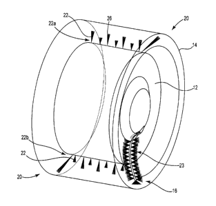
Figure 2 illustrates inner drum 12 removed from washing machine 10 (for
illustration
purposes) and configured with a brush system 20 in accordance with one
embodiment. A
portion of the outer drum 14 is illustrated in dashed lines at the bottom of
the figure. In one
embodiment, brush system 20 includes a plurality of brush sets 22. In one
example, each of
brush sets 22 are inserted through drum holes 18 that are provided in inner
drum 12. In most
instances, drum holes 18 are provided in inner drum 12 to allow water and
detergent to flow
in and out of inner drum 12 in accordance with the wash cycle of washing
machine 10.
In accordance with one embodiment, a plurality of brush sets 22 is inserted
into a
plurality of drum holes 18 in inner drum 12 such that each penetrate into drum
cavity 16.
When inner drum 12 rotates within outer drum 14 with brush sets 22 in place,
brush sets 22
are adapted to clean surfaces within drum cavity 16 and remove deposits.
3
CA 02770807 2012-03-08
In one embodiment, the size and orientation of brush sets 22 can be varied to
ensure
cleaning of surfaces within drum cavity 16. As illustrated in Figure 2, some
brush sets 22 are
angled relative to the surface of inner drum 12 and are used toward the edges
of inner drum
12 such that they can clean sidewall surfaces. Other brush sets 22 are
oriented substantially
perpendicular to the surface of inner drum 12 and have differing brush lengths
to form an
alternating medium and short pattern throughout the center area of inner drum
12. Each of
brush sets 22 are configured to have bristles that penetrate through a hole in
drum 12 and
clean surfaces in drum cavity 16 with rotation of the drum.
Furthermore, in one embodiment, sidewall brushes 23 can be installed on the
side of
inner drum 12 to further clean surfaces on that side. In one embodiment,
sidewall brushes 23
are not attached through holes 18, but are instead attached to the sidewall of
the drum and
will sweep the front sidewall of the inner and outer drums 12 and 14. In one
example, inner
drum 12 includes a slight bevel around the opening, over which a slot in brush
23 can placed.
Brush 23 is well configured to get brushes on surfaces that are otherwise hard
to reach.
Figure 3 illustrates brush set 22 in accordance with one embodiment. Brush set
22
includes base 24 and bristles 26. In one embodiment, brush set 22 is
configured such that
base 24 fits snugly against inner drum 12 adjacent a drum hole 18 such that
bristles 26
penetrate into drum cavity 16 and extend against a surface of outer drum 14.
As such, when
brush sets 22 are attached to inner drum 12 in operation, the drum rotation
will cause bristles
26 to brush a surface of outer drum 14, thereby cleaning away deposits and
residue.
In one embodiment, base 24 has a contact surface 27 that is configured to be
immediately proximate to the surface of inner drum 12 when base 24 in
installed onto inner
drum 12. In one embodiment, base 24 is further configured with an adhesive
along contact
surface 27 such that base 24 will stick to inner drum 12 and ensure that brush
set 22 will not
easily fall off during the rotation of inner drum 12.
Figures 4a-4b illustrate inner drum 12 within outer drum 14 with washing
machine 10
removed for illustration purposes (drum holes 18 are also removed from the
figure to
simplify the illustration). Drums 12 and 14 are configured with a brush system
20 in
accordance with one embodiment. Brush system 20 includes a plurality of brush
sets 22
inserted through drum holes 18 (illustrated in Figure 2) provided in inner
drum 12.
4
i
CA 02770807 2012-03-08
In one embodiment illustrated in Figure 4a, individual brush sets 22 are added
to
inner drum 12 and project up to clean the surface of outer drum 14. In one
embodiment,
individual brush sets 22 are inserted across the width of inner drum 12 in a
first row 22a and
a second row 22b. In one embodiment, first row 22a is offset 180 degrees
relative to second
row 22b (that is, first row 22a is at the "top" when second row 22b is at the
"bottom") in
order to limit any impact or contribution to imbalance of inner drum 12. In
another
embodiment illustrated in Figure 4b, individual brush sets 22 are added to
outer drum 14 and
project down to clean the surface of inner drum 14.
In addition, in one embodiment, the length of bristles 26 for each of the
brush sets 22
is varied. For example, in one embodiment, long and short lengths for bristles
26 are
alternated across the width of inner drum 12. In one example, an opposite
order is used for
the first 22a and second rows 22b of brush sets 22, such that if long bristles
26 are used on
the first brush set 22 in first row22a, then short bristles 26 are used on the
first brush set 22 in
the second row22b, which is 180 degrees offset from it. Each next brush set 22
in each row
then alternates in bristle length with the next adjacent brush set 22. In
other embodiments,
other variations of length and patterns are used.
The independent brush design of brush sets 22 is unique in that they can be
custom
arranged in inner drum 12. In one embodiment, brush sets 22 are easily
distributed across
inner drum 12 and offset any weight imbalance caused by their addition,
thereby resulting in
nearly no vibration during the rotation of inner drum 12 within outer drum 14
while brush
system 20 is in place during operation of washing machine 10. Such
independence and
balance is not achieved, for example, where a single brush assembly with a
series of bristles
is installed across the entire width of a drum. Also, with such a single brush
assembly, there
is no way to easily develop a universal pattern that will meet the hole
pattern requirements of
all existing drums. Using a one-to-one correspondence between each brush set
22 and each
drum hole 18 of inner drum 12 allows for this independent arrangement of
brushes and ease
of weight distribution and balance.
In another embodiment, brush sets 22 are configured to be so small and light
that their
addition to inner drum 12 will not contribute significantly to any weight
imbalance. In such
an embodiment, there would be no need to use any particular pattern to
installing brush sets
22 across inner drum 12.
5
CA 02770807 2012-03-08
Figures 5a-5b together illustrate brush set 22 in accordance with one
embodiment. In
one example, brush set 22 includes base 24, bristles 26 and bristle holder 28,
and Figure 5a
illustrates bristles 26 and bristle holder 28, while Figure 5b illustrates
base 24. In one
embodiment, bristles 26 and bristle holder 28 are formed into a unitary piece.
In various
embodiments, bristles 26 are made of nylon, plastic, metals, various
composites thereof, or
any of a variety of relatively stiff materials. In one embodiment, bristle
holder 28 is formed
over bristles 26 and holds them together.
Base 24 is configured with a base cavity 29 for receiving bristle holder 28,
and in one
embodiment, its shape complements the shape of holder 28. Base 24 has a
contact surface 27
that can be glued or otherwise fixed to inner drum 12. The combination of
bristles 26 and
bristle holder 28 can be inserted through base cavity 29 of base 24, after
contact surface 27 of
base 24 is adhered to a drum. In various embodiments, base 24 is a rigid or
semi-rigid rubber
or plastic material.
In one embodiment, bristle holder 28 is shaped to complement the shape of base
cavity 29 such that when bristle holder 28 is inserted into base cavity 29
there is a slight
interference between bristle holder 28 and base 24 so that bristle holder 28
will not easily
dislodge therefrom. As such, even during a wash cycle bristle holder 28 and
bristles 26 will
be held firmly in place by base 24. In one embodiment, projections 29a are
added to base
cavity 29 and are configured to further engage bristle holder 28 once
inserted. These can
further ensure that bristles 26 will not move once inserted. Alternatively, or
in addition, a
cover or cap can be added to base 24 so that bristle holder 28 can be fully
enclosed in base 24
once inserted.
In one embodiment, base 24 can be configured for multiple uses over many wash
cycles of washing machine 10, while bristles 26 will typically wear during use
and may have
a shorter useful lifespan. As such, new bristles 26 and bristle holder 28 can
be easily inserted
into base 24, which can be re-used in some embodiments. In one embodiment,
contact
surface 27 of base 24 is fitted with an adhesive that will hold up over many
wash cycles of
washing machine 10. As such, base 24 can be left in place even after bristle
holder 28 and
bristles 26 are removed, thereby exposing hole 18 in drum 12 for normal wash
cycle
operation.
6
i
CA 02770807 2012-03-08
Figures 6a-6d illustrate the assembly of a brush set 22 into inner drum 12. In
Figure
6a, alignment tool 30 is illustrated centered on a drum hole 18 in inner drum
12. In one
embodiment, alignment tool 30 has a pointed end 32 configured to fit into hole
18 thereby
centering alignment tool 30 on hole 18. Furthermore, alignment tool 30 has a
lower section
34 that is generally shaped to receive base 24 (which is not shown in Figure
6a to better
illustrate tool 30). In one example, the shape of lower section 34 of
alignment tool 30
substantially complements the shape of base cavity 29 of base 24.
In Figure 6b, base 24 is illustrated with alignment tool 30 extending through
it. In the
illustration, base 24 is shown in cross-section so that alignment tool 30
remains visible in the
area passing though base 24. In one embodiment, lower section 34 of alignment
tool 30 fits
snuggly into base 24 such that base 24 is aligned over hole 18 along with
alignment tool 30.
In one embodiment, contact surface 27 of base 24, which is adjacent inner drum
12, has an
adhesive on it such that base 24 will be secured in this centered position
over hole 18 even
after alignment tool 30 is removed.
In Figure 6c, alignment tool 30 is removed from base 24 and bristles 26 and
bristle
holder 28 are being inserted through base 24 and hole 18. In one embodiment,
base 24 has a
partially stepped base cavity 29 that is configured to receive bristle holder
28 once it is fully
inserted. In one embodiment, projections 29a are provided on portions of base
cavity 29 to
ensure bristle holder 28 is firmly retained in base 24. Figure 6d illustrates
bristle holder 28
fully inserted into base 24 such that bristles 26 extend through drum hole 18
in inner drum 12
toward outer drum 14.
Figure 7 illustrates brush set 22 in accordance with one embodiment. Brush set
22
includes base 44, bristle holder 28 and bristles 26. In one embodiment, brush
set 22 is
configured such that base 44 fits snugly against inner drum 12 adjacent a drum
hole 18 such
that bristles 26 penetrate into drum cavity 16 and extend against outer drum
14. As such,
when brush sets 22 are inserted into inner drum 12 in operation, the drum
rotation will cause
bristles 26 to brush the inner surface of outer drum 14, thereby cleaning away
deposits and
residue.
In addition, contact surface 47 of base 44 is angled relative to base cavity
49 into
which bristle holder 28 is inserted. As such, when contact surface 47 is glued
or otherwise
secured to inner drum 12 about a hole 18, bristles 26 extend from inner drum
12 at an angle
7
CA 02770807 2012-03-08
rather than perpendicular therefrom. Figure 2 illustrates a variety of brush
sets 22, some of
which have a base 44 having a contact surface 47 that is substantially angled
relative to inner
drum 12 (those at the edges) and some of which have a base 24 having a contact
surface 27
that is substantially perpendicular to inner drum 12 (those in between the
ones on the edges).
One skilled in the art understands that a variety of relative angles may be
used to provide that
bristles project from drum 12 is a variety of relative angles, in order to
best optimize their
ability to clean.
In one embodiment, bristle holder 28 and bristles 26 can be configured to be
universal
relative to base 24 and base 44. In other words, the same bristle set, that
is, combination of
bristle holder 28 and bristles 26, could be used in either a base with an
angled cavity to
contact surface relationship, such as base 44, or a base with a substantially
perpendicular
cavity to contact surface relationship, such as base 24.
In other embodiments, there are various modifications to brush system 20. For
example, brush system 20 is described above with respect to individual brush
sets 22 being
inserted through holes in inner drum 12 out toward outer drum 14. In a very
similar fashion,
brush system 20 can include individual brush sets 22 being inserted through
holes in outer
drum 14 in toward inner drum 12. In typical washing machine applications,
although drum
holes 18 are often provided in the inner drum 12, holes are not typically
provided in outer
drum 14. As such, in some instances, holes may be added to either or both of
drums 12 and
14 by drilling into the drums so that brush sets can be added. As such,
surfaces within drum
cavity 16 may be accesses and cleaned with brush system 20 by inserting brush
set 22
through outer drum 14 to cavity 16, into inner drum 12 to cavity 16, or a
combination
thereof.
Figures 8a-8b illustrate an alternative base 64, which can be used in a brush
system
20 in accordance with one embodiment. In one embodiment, either or both of
drums 12 and
14 are drilled into to create holes 18 in the drums. Once these holes 18 are
added, base 64 is
inserted into the holes. Base 64 is similar to base 24 described above, but
base 64
additionally includes base clips 66a and 66b. In one embodiment, base clips
66a and 66b are
angled in part so that they are easily insertable through a hole 18 from a
first surface 14a of
drum 14. Once fully inserted therethrough, base clips 66a and 66b will lock
against a second
8
i
CA 02770807 2012-03-08
surface 14b of drum 14 that is opposite the first surface. As such, in one
embodiment, base
64 remains in place and is not removed.
Once in place, base 64 functions similarly to base 24 and 64 above. As such,
bristle
holder 28 and bristles 26 can be configured to be universal relative to base
24, base 44 and
base 64. In other words, the same bristle set, that is, combination of bristle
holder 28 and
bristles 26, could be used in any of these bases.
Because base 64 allows installation in any custom-drilled hole, brush system
20 using
base 64 can be installed into virtually any type of washing machine, including
a front load, a
top load, a commercial or a residential machine.
Figure 9 illustrates a brush set 72 installed into inner drum 12 in accordance
with one
embodiment. In one embodiment, brush set 72 includes an integrated base and
bristle holder
78 and bristles 76. In one embodiment, holder 78 is formed over bristles 76
and holds them
together. Brush set 72 is inserted through a hole 18 in inner drum 12. In one
embodiment, a
lower surface 77 of holder 78 is adhered to the drum 12 with an adhesive.
Bristles 76
projection from the drum then clean adjacent surfaces as described above with
the other
embodiments. Because integrated base and bristle holder 78 has a integrated
base in one
embodiment, there is no need for a separate base, such as base 24 above.
Figures IOa-10b illustrate further embodiments used with brush system 20.
Figure
10a illustrates a cavity 89 formed in an inner drum 12. In one embodiment,
cavity 89 is
configured for receiving a bristle holder 28, similar to bristle holder 28 in
Figure 5a, and in
one embodiment, the shape of cavity 89 complements the shape of bristle holder
28. As
such, the combination of bristles 26 and bristle holder 28 can be inserted
through cavity 89 of
inner drum 12 to form a brush set. In effect, such a brush set has a base
(such as base 24
above) integrated into inner drum 12 so that no additional base 24 is needed.
In one
embodiment, projections 89a are added to cavity 89 and are configured to
further engage
bristle holder 28 once inserted. These can further ensure that bristles 26
will not move once
inserted. Alternatively, or in addition, a cover or cap can be added.
Figure I Ob illustrates a threaded attachment 99 formed adjacent a hole on
inner drum
12. In one embodiment, threaded attachment 99 is configured for receiving a
bristle holder
88, similar to bristle holder 28 in Figure 5a. In one embodiment, bristle
holder 88 includes
threads 88a, which are configured to be screwed into threads 99a of threaded
attachment 99.
9
I
CA 02770807 2012-03-08
This will firmly seat bristle holder 88 against inner drum 14 such that
bristles 96 will extend
out to outer drum 14 (a portion of which is illustrated at the bottom of the
figure). Once
bristle holder 88 is screwed into threaded attachment 99, this ensures that
bristles 86 will not
move once inserted.
In one embodiment, brush system 20 could be sold with or installed in a new
washing
machine. In another embodiment, brush system 20 is sold as a kit that can be
used on an
existing washing machine 10. As such, a user that has a washing machine 10
that is
exhibiting signs of build up or mildew in a drum cavity 16 can purchase a
brush system kit
and add it to the washer.
In one example, a brush system kit includes fourteen perpendicular bases 24,
two
angled bases 44, one alignment tool 30, seven 1.5 inch long bristles 26 (as
measured from the
top of bristle holder 28 to the end if the bristles 26), seven 2.5 inch long
bristles 26, two 5
inch long bristles 26, and a sidewall brush 23. Each independent brush set 22
can then be
installed in the inner drum 12 (as described relative to figures 6a-6d above)
and arranged to
easily offset any weight distribution and result in nearly no vibration.
For example, with such a kit, brush sets 22 can be installed as follows:
= two angled bases installed on the ends, with one 5" long bristles set
installed on the
end of the top of the inner drum and one 5" long bristles set installed on the
end of the
opposing end of the bottom of the inner drum;
= seven perpendicular bases installed on the top of the inner drum, with four
2.5" long
bristles sets alternating with three 1.5" long bristles sets; and
= seven perpendicular bases installed on the bottom of the inner drum, with
three 2.5"
long bristles sets alternating with four 1.5" long bristles sets.
In addition to these independent brush sets 22, a sidewall brush 23 is
provided to
reach the front sidewall of the drum. In one embodiment, sidewall brush 23 is
intended to be
used as a hand brush, and in another embodiment it can be seated firmly on the
rim of the
inner drum 12.
The above-described exemplary kit is generally illustrated in Figure 2, for
example.
The actual diameter of brush sets 22 and overall length of brushes 26 will
vary from
application to application. In some examples, washing machines have holes in
inner drum 12
that are approximately 0.147 inches in diameter, but in other washers this
will vary from
CA 02770807 2012-03-08
model to manufacturer. As such, brush sets 22 can be designed to fit existing
machines and
their various known sizes. In another embodiment, brush sets 22 can be sold as
a one size
and the user can be provided with a drill bit to drill holes that will fit
with the provided size
of brush set.
Furthermore, the distance between the inner and outer drums 12 and 14 will
vary
from model to manufacturer. As such, the particular length of the bristles 26
installed in any
brush set 22 can be varied to match the application into which it is
installed. In one
embodiment, the user can be provided with longer bristles 26 that are to be
cut down to the
appropriate size dependent on the particular machine on which it will be used.
In accordance with one embodiment, brush system 20 cleans a washing machine
and
extends its useful life. Brush system 20 provides a physical means to remove
the unwanted
residue from within a washing machine. Brush system 20, using an independent
brush
design can be combined with a mild detergent and bleach solution, to overcome
most of the
mold, mildew and other deposits that naturally occur in a washing machine.
As such, in some embodiments, brush system 20 may offer a significant
reduction in
the odors associated with unwanted residue. It can also be easy to install,
even in after
market applications, and yet does not require any disassembly of the washing
machine and
still removes the undesirable odor and contaminates from the outer drum. It
can be installed
by an average homeowner without professional assistance and without
complications. Brush
system 20 includes an independent brush design that is useful for any model of
washing
machine. It can be particularly useful for people who have heightened
sensitivity to mold,
mildew and other allergens.
The particular use of brush system 20 can vary in accordance with certain
factors.
For example, the frequency with which brush system 20 is implemented and used
in a
washing machine may depend on the frequency of use of the washing machine, the
water
supply (e.g., well or city water), hard or soft water, types of detergents
used for regular
laundering, contaminants being washed from clothing, and climate, among
others.
In one embodiment, brush system 20 can be used on a semi-annual basis. In one
example, directions for the system 20 can be provided to a user, especially
where it is offered
as a kit. One example set of instructions includes the following steps:
1. Ensure the machine is off and not in a wash cycle.
I1
CA 02770807 2012-03-08
2. Open door of washing machine to access the inner drum.
3. With the inner drum dry and clean from debris, wipe down the inner drum
with a paper towel.
4. Use an angled base at the bottom (or rear) of the inner drum.
a. Remove adhesive protector to expose adhesive.
b. Use alignment tool provided to guide the base over the selected hole in the
end of the drum.
c. Affix the base to the inner drum so the brush set is pointed away.
5. Install a perpendicular base (skipping 2 holes between each base) on the
row
of holes on the bottom of the inner drum, working toward you.
a. Remove adhesive protector and use alignment tool to affix remaining 7 bases
to the bottom of the inner drum.
6. Use an angled base at the top (or front) of the inner drum.
a. Remove adhesive protector to expose adhesive.
b. Use alignment tool provided to guide the base over the selected hole in the
end of the drum.
c. Affix the base to the inner drum so the brush set is pointed away.
7. Install a perpendicular base (skipping 2 holes between each base) on the
row
of holes on the top of the inner drum, working toward you.
a. Remove adhesive protector and use alignment tool to affix remaining 7 bases
to the top of the inner drum.
8. Install the long (5") brush set in the angled bases.
a. * * * Note*** It is easier to install the brush set if you gently move the
inner
drum back and forth (approximately I") while inserting brush set into the
base.
9. Insert the medium (2.5") brush sets in every other base on the bottom and
top
row of bases.
10. Insert the short (1.5") brush sets in the remaining bases that are not yet
populated.
11. Ensure the cover to each base is properly secured.
12. Ensure that the bases are properly secured to the inner drum and adhesive
is
holding well.
12
CA 02770807 2012-03-08
13. Add a small amount of detergent and a small amount of bleach into the
appropriate dispensers(1/8 capful of detergent, and approximately the same
amount of
bleach)
14. Machine settings: Close door or cover and select the quick wash setting,
if
quick wash is not available, select delicate cycle. Select a hot wash cycle
and low spin.
15. Select the spin setting as low.
16. Do not load clothing into the machine, particles and contaminants will be
removed from the walls of the outer drum and will contaminate clothes. This
wash cycle will
have no clothing in it.
17. Allow machine to complete a wash cycle.
18. Once the cycle is complete simply open the door or cover and hold the base
unit to gently remove the brush set from the inner drum.
19. Ensure no adhesive deposits are remaining in the inner drum; remove any
that
are remaining with a rolling action of a finger.
20. Wash cycle is complete.
21. Discard brush sets and retain the base units.
Although specific embodiments have been illustrated and described herein, it
will be
appreciated by those of ordinary skill in the art that a variety of alternate
and/or equivalent
implementations may be substituted for the specific embodiments shown and
described
without departing from the scope of the present invention. This application is
intended to
cover any adaptations or variations of the specific embodiments discussed
herein. Therefore,
it is intended that this invention be limited only by the claims and the
equivalents thereof.
13