Note: Descriptions are shown in the official language in which they were submitted.
CA 02770931 2012-02-10
WO 2010/022069 PCT/US2009/054186
DRUG INFUSION SYSTEM WITH REUSABLE AND DISPOSABLE
COMPONENTS
PRIORITY CLAIM
[1] The present application claims the benefit of
copending United States Provisional Patent Application No.
61/089749, filed 18 August 2008; the present application
also claims the benefit of copending United States
Provisional Patent Application No. 61/227157, filed 21 July
2009; all of the foregoing applications are incorporated
herein by reference in their entireties.
BACKGROUND OF THE INVENTION
[2] The present invention relates to infusion devices
and more particularly to such devices that enable liquid
medicaments to be conveniently and safely self-administered
by a patient. One liquid medicament that is often self-
administered by a patient is insulin, and for ease of
description, the administration of insulin is generally used
herein for exemplary purposes although the invention should
not be limited by that exemplary use.
[3] Administration of insulin has traditionally been
accomplished using a syringe. Recently, needle carrying pen-
like devices have also been employed for this purpose. Both
forms of insulin administration require the patients to
stick themselves each time they inject insulin, often many
times a day. Additionally, a new clean needle must be
mounted on the device each time they are used, and disposed
of after each use, creating the additional problem of having
the "sharps" with them whenever the patient needs to
administer insulin, and to safely dispose of them after each
use. Thus, these traditional forms of insulin administration
1
CA 02770931 2012-02-10
WO 2010/022069 PCT/US2009/054186
have been a rather pervasive intrusion in the lives and
routines of the patients who have had to adopt and employ
them.
[4] More recently, insulin pumps attached by tubing to
an infusion set mounted on the patient's skin have been
developed as an alternative form of insulin administration.
Such pumps may be controlled by a programmable remote
electronic system employing short range radio communication
between a control device and electronics that control the
pump. While such devices may involve fewer needle sticks,
they are expensive to manufacture. They are also complex to
operate and cumbersome and awkward to wear. Further, the
cost of such devices can be many times the daily expense of
using a traditional injection means such as a syringe or an
insulin pen.
[5] Devices of the type mentioned above also require a
significant amount of training to control and thus use the
devices. Great care in programming the devices is required
because the pumps generally carry sufficient insulin to last
a few days. Improper programming or general operation of the
pumps can result in delivery of an excessive amount of
insulin which can be very dangerous and even fatal.
[6] Many patients are also reluctant to wear a pump
device because they can be socially awkward. The devices are
generally quite noticeable and can be as large as a pager.
Adding to their awkwardness is their attachment to the
outside of the patients clothes and the need for a catheter
like tubing set running from the device to an infusion set
located on the patient's body. Besides being obvious and
perhaps embarrassing, wearing such a device can also be a
serious impediment to many activities such as swimming,
bathing, athletic activities, and many activities such as
2
CA 02770931 2012-02-10
WO 2010/022069 PCT/US2009/054186
sun bathing where portions of the patient's body are
necessarily uncovered.
[7] In view of the above, a more cost effective and
simple device has been proposed whereby an injection system
is discreetly attached directly to the skin of the patient.
One example of such a device is described in detail in U.S.
Application 12/147,283 filed June 26, 2008 and titled
DISPOSABLE INFUSION DEVICE WITH REDUNDANT VALVED SAFETY,
which application is owned by the assignee of this
application and incorporated herein by reference in its
entirety. Such a device may be attached to the patient
under the patient's clothing to deliver insulin into the
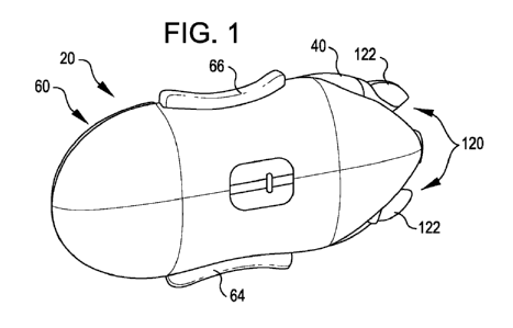
patient by the manual pumping of small doses of insulin out
the distal end of a temporarily indwelling cannula that is
made a part of the pump device. The device may be made
quite small and, when worn under the clothes, entirely
unnoticeable in most social situations. It may still carry
sufficient insulin to last a patient several days. It can
be colored to blend naturally with the patient's skin color
so as not to be noticeable when the patient's skin is
exposed. As a result, insulin for several days may be
carried by the patient discreetly, and conveniently applied
in small dosages after only a single needle stick. For
another description of devices of this type, reference may
also be had to co-pending application Serial Number
11/906,130, filed on September 28, 2007 for DISPOSABLE
INFUSION DEVICE WITH DUAL VALVE SYSTEM, which application is
owned by the assignee of this application and hereby
incorporated herein by reference in its entirety.
[8] Although relatively discrete, the patient may have
a reason to remove the system entirely. Likewise, if the
drug delivery system is accidentally dislodged from the
patient, it would be advantageous to be able to salvage the
medicament and pump, and to replace only the minimum amount
3
CA 02770931 2012-02-10
WO 2010/022069 PCT/US2009/054186
of the system. Where the pump, insulin supply and cannula
are integral and non-separable units, removing just the pump
or just the insulin, or adding a different liquid medicament
is not generally feasible. Sometimes it would be
advantageous to be able to remove the pump unit, the insulin
reservoir, or the entire device, and to reassemble and use
parts of the drug delivery system. Additionally, since the
portion of system that contains the cannula needs to be
removed and reinstalled every three days pursuant to current
medical and regulatory practice, it would be advantageous to
be able to remove the other portions of the drug delivery
system from the portion with the cannula, and reattach them
to a new cannula containing portion, thus avoiding replacing
them with every use.
[9] Further, it would be advantageous if the device
was configured to utilize commercially available reservoirs
or cartridges. For example, glass cartridges are presently
used for insulin injection pens, which are readily available
to the patient with a prescription. It would be beneficial
to some patients to combine the availability of these
cartridges with a discreet device that removes the attendant
problems of a syringe-pen. Such a device would also decrease
the attendant manufacturing costs of a device that utilizes
proprietary reservoirs. More importantly, it would mitigate
the inconvenience to the patient of filling or refilling a
reservoir and the attendant problems associated with the
patient performing that task.
[10] Therefore there is a need for an invention that
makes it possible to have a small, simple and discreet drug
delivery system and yet be able to remove various components
of the drug delivery system from each other, and to reattach
them to each other without the need to discard the entire
system.
4
CA 02770931 2012-02-10
WO 2010/022069 PCT/US2009/054186
SUMMARY OF THE INVENTION
[11] In one embodiment, a drug infusion system
comprises a base having a cannula well arranged to receive a
cannula that conducts the drug to beneath a wearer's skin.
The base further includes a base surface arranged to attach
to the skin of the wearer. The base includes the cannula
well and is arranged to dispose a cannula to extend from the
base surface to beneath the wearer's skin. The base further
includes an inlet arranged to receive the drug, a conduit
that conducts the drug from the inlet to the cannula well,
and a first self sealing penetrable barrier moveable with
respect to the inlet. The system further includes a reusable
drug dispenser removably attachable to the base and having a
second self sealing penetrable barrier, a reservoir arranged
to hold the drug, and a pump that pumps the drug to the
second self sealing penetrable barrier. The first and second
self sealing penetrable barriers are arranged to engage each
other and to be penetrated by the inlet of the base when the
reusable dispenser is attached to the base to form a
antiseptic connection between the cannula well and the
reservoir.
[12] The inlet may comprise a needle. The system may
further comprise a latch assembly that releasably holds the
reusable dispenser on the base. The latch assembly may
include a male/female clasp arrangement. The clasp
arrangement and first and second sealing penetrable barrier
may be arranged such that as the male/female clasp
arrangement engages, the first and second self sealing
penetrable barriers engage each other and are penetrated by
the needle to discard the entire system.
[13] The pump may be any one of acceptable drug
delivery pumps which may include, for example, a piston
5
CA 02770931 2012-02-10
WO 2010/022069 PCT/US2009/054186
pump, a peristaltic pump, a screw pump, a membrane pump, a
metering device, and a gas driven positive displacement
pump. The system may further comprise a cannula set
including a receiving pike and the cannula. The receiving
pike may be arranged to be received within the cannula well
in fluid communication with the conduit, whereby a fluid
connection is formed from the cannula through the conduit to
the reservoir. The cannula set may further include a top
sealing member. The cannula set may further include a port
aligned with the cannula that facilitates placement of the
cannula set into the cannula well and a port cover that
blocks the port to preclude direct access to the cannula
through the port after the cannula set is received within
the cannula well. The cannula may be arranged to be deployed
beneath the wearer's skin with a drive needle that extends
through the port and carries the cannula into the deployed
position and the cover may be arranged to block the port
upon withdrawal of the needle from the cannula set after
deployment of the cannula. The port cover may be formed of
resilient material and be arranged to spring over and block
the port responsive to the drive needle being withdrawn from
the port.
[14] The base may include a guide that guides the
reusable dispenser into attachment on the base. The base
lower surface may include an adhesive that attaches the base
to the wearer's skin. The base may be coextensive with the
reusable dispenser when the reusable dispenser is attached
to the base. The reusable dispenser may include an inlet
cavity adjacent the second self sealing penetrable barrier
that receives the inlet of the base when the reusable
dispenser is attached to the base. The inlet cavity may be
arranged to receive the drug from the reservoir and provide
the drug to the inlet of the base. The reusable dispenser
may include a pair of actuators operatively associated with
6
CA 02770931 2012-02-10
WO 2010/022069 PCT/US2009/054186
the pump for causing the pump to pump the drug form the
reservoir to the cannula upon concurrent actuation of the
actuators.
[15] The inlet of the base may have a distal end that
penetrates the first and second self sealing penetrable
barriers when the reusable dispenser is attached to the
base. The first self sealing penetrable barrier may be
moveable with respect to the inlet of the base and the base
may further include a biasing element that urges the first
self sealing penetrable barrier against the second self
sealing penetrable barrier when the reusable dispenser is
attached to the base.
[16] The system may further comprise a vent immediately
adjacent the second self sealing penetrable barrier. The
vent may comprise a hydrophobic vent covered by a one-way
valve that allows the passage of air out the vent, does not
allow liquid such as liquid medicament out the vent, and
after the pathway is vented, does not allow air back into
the fluid pathway.
[17] The reusable portion may comprise a separate
reservoir unit that holds the drug to be delivered. The
reservoir unit may be engageable with the dispenser such as
a pump portion, and both portions may be releasably secured
to the base. The reusable portion may further comprise at
least one latch that maintains the dispenser and reservoir
unit in engagement. The at least one latch may comprise a
latching projection and a projection receiving slot.
[18] The latching projection may be carried by the
dispenser and the projection receiving slot may be formed in
the reservoir unit. The system may further comprise an
antiseptic coupling between the dispenser and reservoir
unit.
[19] An alternative embodiment for a drug infusion
system is also disclosed. The alternative embodiment
7
CA 02770931 2012-02-10
WO 2010/022069 PCT/US2009/054186
comprises a base configured to receive a cannula that
delivers a drug to beneath a wearer's skin. The base further
includes a base surface arranged to attach to the skin of
the wearer and is arranged to dispose the cannula to extend
from the base surface to beneath the wearer's skin. The
device further comprises a reusable drug dispenser removably
attachable to the base. The reusable drug dispenser has a
pump unit configured to establish fluid communication
between a removably attachable drug reservoir and the
cannula, whereby the pump unit pumps the drug to the wearer
upon activation of the pump by the wearer.
[20] The pump unit may further comprise an inlet
configured to contact the drug within the reservoir, and the
inlet may be a needle. The pump unit may also comprise a
receiving unit configured to receive the reservoir. Such a
receiving unit may be tubular to accommodate a cylindrical
reservoir. The receiving unit may comprise a cavity
configured to hold the reservoir. The pump unit may
comprise an encasing unit configured to hold the reservoir,
and such an encasing unit may be positioned to one side of
the pump unit, thereby allowing a lower profile.
[21] In another embodiment, a drug infusion assembly
comprises a base including a base surface arranged to attach
to the skin of a wearer. The base includes a cannula
arranged to extend from the base surface to beneath the
wearer's skin and an inlet in fluid communication with the
cannula. The infusion assembly further comprises a pump unit
removably attachable to the base. The pump unit has a cavity
and a latch assembly within the cavity. The cavity is
arranged to receive a cartridge reservoir therein and the
latch assembly is arranged to releasably lock the cartridge
reservoir within the cavity. The pump unit is configured to
establish fluid communication between the releasably locked
cartridge reservoir and the inlet of the base and to pump a
8
CA 02770931 2012-02-10
WO 2010/022069 PCT/US2009/054186
liquid medicament stored in the cartridge reservoir to the
inlet of the base and the cannula upon activation by the
wearer.
BRIEF DESCRIPTION OF THE DRAWINGS
[22] The features of the present invention which are
believed to be novel are set forth with particularity in the
appended claims. The invention, together with further
features and advantages thereof, may best be understood by
making reference to the following description taken in
conjunction with the accompanying drawings, in the several
figures of which like reference numerals identify identical
elements, and wherein:
[23] FIG. 1 is a top perspective view of a drug
infusion system according to an embodiment of the invention;
[24] FIG. 2 is a bottom plan view of the drug infusion
system of FIG. 1;
[25] FIG. 2B is a simplified side view of an
alternative embodiment of the device shown in FIGS. 1 and 2;
[26] FIG. 2C is a side view of the embodiment of FIG.
2B during cannula insertion;
[27] FIG. 2D is a side view of the embodiment of FIG.
2B after cannula insertion;
[28] FIG. 3 is a top perspective view of the base
portion of the system of FIG. 1;
[29] FIG. 4 is a top perspective view of the base
portion of the system of FIG. 1 with a cannula set aligned
therewith for deployment;
[30] FIG. 5 is a partial sectional side view, to an
enlarged scale, illustrating details of the cannula set and
base portion prior to cannula set deployment;
9
CA 02770931 2012-02-10
WO 2010/022069 PCT/US2009/054186
[31] FIG. 6 is a partial sectional side view, to an
enlarged scale, illustrating details of the cannula set and
base portion after cannula set deployment;
[32] FIG. 7 is a bottom perspective view of the
reusable portion of the system of FIG. 1;
[33] FIG. 8 is a top perspective view of the reusable
portion being mated with the base portion of the system of
FIG. 1;
[34] FIG. 9 is a side view in section, to an enlarged
scale, of the antiseptic coupling between the base portion
and the reusable portion prior to their engagement;
[35] FIG. 10 is a side view in section, to an enlarged
scale, of the antiseptic coupling between the base portion
and the reusable portion during the process of their
engagement;
[36] FIG. 11 is a side view in section, to an enlarged
scale, of the antiseptic coupling between the base portion
and the reusable portion after their engagement;
[37] FIG. 12 is a side view in section, to an enlarged
scale, of the antiseptic coupling between the base portion
and the reusable portion of another drug infusion system
according to another embodiment of the invention;
[38] FIG. 13 is a perspective view of another drug
infusion system embodying the invention having detachable
pump component and reservoir component;
[39] FIG. 14 is a top plan view of the system of FIG.
13 showing reservoir and pump components thereof aligned for
engagement;
[40] FIG. 15 is a top plan view of the system of FIG.
13 showing the reservoir and pump components thereof
entering engagement; and
[41] FIG. 16 is a top plan view of the system of FIG.
13 showing the reservoir and pump components thereof after
engagement.
CA 02770931 2012-02-10
WO 2010/022069 PCT/US2009/054186
[42] FIG 17 is a side view in section of the attachment
mechanism between the reservoir portion and pump portion of
one embodiment of the invention;
[43] FIG 18 is a side sectional view to an expanded
scale of the connection mechanism between the reservoir
portion and the pump portion of one embodiment of the
invention;
[44] FIG. 19A is a top view, in perspective, of an
embodiment of the invention using a commercially available
cartridge;
[45] FIG. 19B is a bottom view of the embodiment of
FIG.19A;
[46] FIG. 19C is a partial side view, in section, of
the embodiment of FIG. 19A;
[47] FIG. 20A is a top plan view of another embodiment
of the invention using a commercially available cartridge;
[48] FIG. 20B is a side view, in section, of the
embodiment of FIG. 20A;
[49] FIG. 20C is a side view of the embodiment of FIG.
20A;
[50] FIG. 20D is a top view of the embodiment of FIG.
20A;
[51] FIG. 21A is a top view of another embodiment Of
the invention using a commercially available cartridge;
[52] FIG. 21B is an end view of the embodiment of FIG.
21A;
[53] FIG. 22 is an exploded view of the components of a
further infusion assembly embodying the present invention;
[54] FIG. 23 is a perspective view of the assembled
components of the assembly of FIG. 22;
11
CA 02770931 2012-02-10
WO 2010/022069 PCT/US2009/054186
[55] FIG. 24 is a bottom view, in perspective, of the
assembled components of the assembly of FIG. 22 prior to
deployment on a user;
[56] FIG. 25 is a perspective view, with portions cut
away, illustrating the releasable lock of the cartridge
reservoir within the pump unit;
[57] FIG. 26 is a top plan view, with portions removed,
illustrating the cartridge reservoir being loaded into the
pump unit and just prior to being releasably locked therein;
[58] FIG. 27 is a top plan view, with portions removed,
illustrating the cartridge reservoir after being loaded into
the pump unit and being releasably locked therein;
[59] FIG. 28 is an end view, in perspective, of the
base unit of the assembly of FIG. 22;
[60] FIG. 29 is a top plan view of the assembled
assembly of FIG. 22, with portions removed, illustrating a
first condition of a compression spring contacting a
cartridge reservoir;
[61] FIG. 30 is a side plan view, with portions
removed, of the assembled assembly of FIG. 29;
[62] FIG. 31 is a top plan view of the assembled
assembly of FIG. 29, with portions removed, illustrating a
second condition of the compression spring;
[63] FIG. 32 is a side plan view, with portions
removed, of the assembled assembly of FIG. 31;
[64] FIG. 33A is a top plan view of the assembled
assembly of FIG. 29, with portions removed, illustrating a
nearly empty condition of the cartridge reservoir and the
compression spring;
[65] FIG. 33B is a side plan view, with portions
removed, of the assembled assembly of FIG. 33A;
12
CA 02770931 2012-02-10
WO 2010/022069 PCT/US2009/054186
[66] FIG. 34A is a top plan view of the assembled
assembly of FIG. 22, with portions removed, of a further
embodiment of a compression spring that assists throughout
fluid delivery from a cartridge reservoir;
[67] FIG. 34B is a side plan view, with portions
removed, of the assembled assembly of FIG. 34A;
[68] FIG. 35 is an exploded view, in perspective, of
the pump unit and cartridge reservoir of the assembly of
FIG. 22 just prior to the loading of the cartridge reservoir
into the pump unit;
[69] FIG. 36 is a perspective view of the pump unit and
cartridge reservoir during the loading of the cartridge
reservoir into the pump unit;
[70] FIG. 37 is a perspective view of the pump unit and
cartridge reservoir after the loading of the cartridge
reservoir into the pump unit;
[71] FIG. 38 is a perspective view of the pump unit and
base of the assembly of FIG. 22 during the placement of the
pump unit onto the base;
[72] FIG. 39 is a bottom plan view of the assembled
assembly of FIG. 22 shown during a priming process;
[73] FIG. 40A is an exploded side plan view of the
infusion device and an inserter for deploying the device in
accordance with further aspects of the present invention;
[74] FIG 40B is an exploded view, in perspective, of
the infusion device and inserter of FIG. 40A;
[75] FIG. 41A is a perspective view of the infusion
device and inserter of FIG. 40A after the infusion device
has been loaded into the inserter;
[76] FIG. 41B is a perspective view of the infusion
device and inserter of FIG. 40A after the infusion device
13
CA 02770931 2012-02-10
WO 2010/022069 PCT/US2009/054186
has been loaded into the inserter and after a protective
cannula cover and one adhesive cover have been removed from
the device;
[77] FIG. 42 is a side plan view of the inserter, with
the infusion device therein, against a patient's skin ready
to deploy the device on the patient;
[78] FIG. 43 is a side plan view of the deployed device
having an insertion needle removed therefrom;
[79] FIG. 44 is a perspective view of the insertion
needle being safely stored in a cannula protector of the
assembly of FIG. 22 for sharps disposal;
[80] FIG. 45 is a perspective view of the deployed
device on a patient's skin;
[81] FIG. 46 is a perspective viewing which may be
interpreted as showing either a pump unit being removed from
a deployed base or a replacement pump unit being placed on a
deployed base; and
[82] Fig. 47 is a perspective view which may be
interpreted as showing either a replacement pump being
placed on a replacement base or a partially used pump unit
being placed on a replacement base prior to deployment of
the replacement base.
14
CA 02770931 2012-02-10
WO 2010/022069 PCT/US2009/054186
DETAILED DESCRIPTION OF THE INVENTION
[83] Referring now to FIGS. 1 and 2, they show a drug
infusion system 20 according to a first embodiment of the
invention. The system 20 generally includes a lower base
portion 40 and a reusable drug dispenser portion 60. As will
be seen subsequently, the reusable portion is arranged to be
releasably attached to the base portion 40. In FIGS. 1 and
2, the base portion 40 and reusable portion 60 are fully
engaged or joined together.
[84] The base portion 40 includes a base surface 41
which preferably is coated with an adhesive for attaching
the base portion 40 to the skin of a wearer in need of the
drug, such as insulin, to be delivered by the system 20. To
that end, the base 40, in a manner to be fully described
herein after, is arranged to receive a cannula 100 which,
when deployed, extends from the base surface 41 to beneath
the skin of the wearer for subcutaneous delivery of the
drug. The reusable dispenser portion includes a reservoir
(not shown) for containing the drug and a pump (not shown)
that, when actuated, pumps the drug from the reservoir to
the cannula for delivery. As will be seen subsequently, when
the base 40 and reusable portion 60 are joined together, a
coupling arrangement provides an antiseptic connection there
between. Also, the cannula 100 is a part of a cannula set
which may be replaced in the base 40 when the reusable
portion 60 is removed.
[85] To actuate the pump, the reusable portion 60
includes a pair of actuator buttons 64 and 66. Preferably,
the actuator buttons are arranged with the pump and other
operative internal components of the reusable portion 60 so
that concurrent depression of the actuator buttons 64 and 66
is required to actuate the pump. Infusion devices having
CA 02770931 2012-02-10
WO 2010/022069 PCT/US2009/054186
such functionality are fully described, for example, in
copending application Serial Number 12/147,314 filed June
26, 2008 for DISPOSABLE INFUSION DEVICE WITH PRIME
INDICATOR, which application is assigned to the assignee of
the present invention and incorporated herein by reference
in its entirety. The pump for this or any of the subsequent
embodiments may be any one of acceptable drug delivery pumps
which may include, for example, a piston pump, a peristaltic
pump, a screw pump, a membrane pump, a metering device, and
a gas driven positive displacement pump.
[86] The base 40 and reusable portion 60 are releasably
fixed together by a latch assembly 120. In accordance with
this embodiment, the latch assembly 120 includes a male part
including projections 122 carried by the reusable portion 60
that are snappingly received within slots 124 of the base
40. A further snap-action latch 126 is provided at the
distal end of the system 20 to complete the confinement of
the reusable portion 60 on the base 40.
[87] Alternatively, as shown in FIG. 2B, the system 20'
comprises a reusable drug dispenser 60' and a base portion
40', which is releasably attached to the combined pump unit
and reservoir 60'. Similar to the other embodiments in this
application, the base 40' comprises an adhesive layer (not
shown) configured to adhere to the skin of a wearer. The
base also comprises a cannula well (similar to element 52 in
FIGS. 3 and 4) disposed in the base. Alternatively, the
cannula well may be disposed in the reusable drug dispenser
60'. To that end, the cannula set 102 (shown in FIGS. 5 and
6) is used to drive cannula 100 through cannula exit port
101.
[88] FIG. 2C shows, in accordance with this embodiment,
a cannula 106 that is provided as part of the base 40'. In
this embodiment, the base comprises a needle handle 105
covering the cannula port 101 on proximal (non-skin) side of
16
CA 02770931 2012-02-10
WO 2010/022069 PCT/US2009/054186
the base. Needle handle 105 is attached a to detachable
drive needle 107, which is located on the distal side of the
base 40'. The drive needle 107 is in turn held within
cannula 106 which is affixed to the distal side of base 40'.
Drive needle 107 is configured to introduce the cannula 106
into the skin.
[89] In use, the wearer pushes the base 40' against the
wearer's skin, such that the needle 107 penetrates the skin.
The cannula 106 is carried by the needle 107 through the
tissue to beneath the skin. During this process and
substantially simultaneously, the adhesive layer of the base
40' will make contact with and adhere to the skin. FIG. 2D
illustrates the assembly after the detachable drive needle
is removed. This leaves the base 40' attached to the skin S,
and the cannula 106 extending through tissue beneath the
skin.
[90] The perspective views of FIG. 3 show the base 40
in greater detail. Here it may be seen that the base 40
includes a head portion 42. The head portion 42 includes the
slots 124 that snappingly receive the projections 122 (as
shown in FIGS. 7 and 8) of the reusable portion 60 when the
base 40 and reusable portion 60 are joined together. The
head portion also includes an opening 44 into which a
coupling part of the reusable portion 60 is received to
establish the antiseptic connection between the base 40 and
the reusable portion 60.
[91] The base 40 further includes relieved surfaces 46
that form resulting shoulders 48 and 50. The shoulders 48
and surfaces 46 form guides to guide the reusable portion 60
into proper alignment with the base 40 as they are joined
together. The shoulders 50 provide a stop which is engaged
when the base 40 and reusable portion 60 are finally snapped
together. The opening 44 may also be formed in its proximal
17
CA 02770931 2012-02-10
WO 2010/022069 PCT/US2009/054186
portion as a channel that mates with coupling projection 74
as shown in FIGS. 7 and 9 to guide the aligned base and
reusable portion into final and precise alignment for
accurate attachment. Additionally or alternatively, grooves
57,59 in FIG. 4 may mate with projections 123,125 shown in
FIG. 7 to help guide the two segments together in proper
alignment.
[92] As best seen in FIG. 4, the base 40 further
includes a well 52 that is arranged to receive a cannula set
102 that includes the cannula 100. When the cannula set 102
is deployed, the cannula 100 is resultingly connected to an
inlet within the head portion 42 and accessible through the
opening 44 by the reusable portion.
[93] The cannula set 102 and details of its deployment
will now be described with particular reference to FIGS. 5
and 6. The cannula set 102 generally includes the cannula
100 and a cannula carrier 104. The cannula carrier is
dimensioned to fit accurately in the cannula well 52 of the
head portion 42 of the base 40 (FIG. 4). The carrier 104
includes a receiving pike 106 which is received by a
correspondingly shaped feature 54 of the well 52. The
feature 54 is in fluid communication with a conduit 108
through which the drug, such as insulin, is caused to flow
by the pump. The drug hence flows through the conduit 108,
through the feature pike 106, and to the cannula 100 for
delivery.
[94] The carrier further includes a port 110 through
which a deployment needle (not shown) may be inserted. Prior
to cannula deployment, the deployment needle extends through
the port 110, through a passage 112, and through the cannula
100. The use of a deployment needle to subcutaneously place
a cannula is described in greater detail in application
12/147,295 titled DISPOSABLE INFUSION DEVICE WITH
AUTOMATICALLY RELEASABLE CANNULA DRIVER concurrently owned
18
CA 02770931 2012-02-10
WO 2010/022069 PCT/US2009/054186
by applicant and incorporated herein in its entirety. The
cannula set 102 is thus carried on the deployment needle.
When the cannula set is deployed, the needle is retracted
leaving the cannula set deployed as shown in FIG. 6.
[95] To preclude direct access to the cannula 100
through the port 110 after deployment needle removal, the
cannula set further includes a port cover 114. The port
cover is preferably formed of resilient material and is
arranged to spring over and block the port responsive to the
drive needle being withdrawn from the port. Such a port
cover is fully described, for example in co-pending
application Serial Number 12/147,306 filed June 26, 2008 for
DISPOSABLE INFUSION DEVICE WITH CANNULA PORT COVER, which
application is assigned to the assignee of the present
invention and incorporated herein by reference in its
entirety. The port cover 114 together with a top 116 of the
carrier 104 form a top sealing member of the carrier 104.
[96] FIG. 7 shows the bottom view of the reusable
portion 60. Here it may be seen that the reusable portion 60
includes a coupling projection 74 that is arranged to be
received by the opening 44 of the base 40 when the base 40
and reusable portion are attached. It may also be seen that
the reusable portion 60 includes the latch 126 at its distal
end to complete confinement of the reusable portion 60 on
the base 40.
[97] FIG. 8 shows the reusable portion 60 being
attached to the base 40. The projections 122 are aligned
with and ready to be captured by the slots 124. When the
reusable portion 60 reaches its final position on the base
40, it will cover essentially all of the base including the
head portion 42 (FIGS. 3 and 4) as shown in FIG. 1.
[98] FIGS. 9-11 show the establishment of the fluid
coupling between the base 40 and the reusable portion 60 as
the reusable portion is brought into engagement with the
19
CA 02770931 2012-02-10
WO 2010/022069 PCT/US2009/054186
base. FIG. 9 shows the base 40 and reusable portion 60 prior
to engagement.
[99] Here the base 40 may be seen to include an inlet
chamber 140. Extending through the inlet chamber 140 is a
needle 142 that forms an inlet to the base 40. The needle
142 has a sharpened distal tip 143. The distal end of the
inlet chamber 140 is sealed with a self sealing, penetrable,
barrier or septum 144. A spring 146 urges the septum 144 in
the distal direction. The reusable portion 60, in turn,
includes a conduit 76 within the coupling 74. The coupling
is sealed with a self sealing, penetrable, barrier or septum
78. Immediately adjacent the septum 78 is a one-way valve 77
to vent the conduit 76. This permits the drug, such as
insulin, to be primed within the conduit so as to be in
contact with the septum to eliminate air bubbles which might
otherwise form.
[100] FIG. 10 shows the base 40 and reusable portion 60
just as they engage. Here, it can be seen that the coupling
74 has entered the opening 44 and that the barriers 144 and
78 have engaged each other. When the reusable portion 60
reaches its final position on the base 40 as shown in FIG.
11, the tip 143 of the inlet needle 142 has pierced through
the septum 144 and the septum 78 to enter the conduit 76.
The spring 146 is also compressed. As a result, a sealed
fluid connection is established from the conduit 76 in fluid
communication with the pump, through the inlet needle 142,
through the conduit 108, and to the cannula 100 for drug
delivery.
[101] When it is necessary to remove the reusable
portion 60 from the base 40, as the reusable portion 60 is
pulled from the base 40, the compressed spring 146 forces
the septum 144 distally until it once again seals the inlet
chamber 140 as shown in FIG. 9. In addition to the inlet of
the base 40 being sealed, the needle 142 is safely retracted
CA 02770931 2012-02-10
WO 2010/022069 PCT/US2009/054186
back into the inlet chamber 140 to protect the wearer from
being accidently pierced by the needle 146. More
specifically, the opening 44 to the inlet chamber 140 may be
made small enough to eliminate the danger of even the
smallest of fingers of children, for example, from gaining
access to the inlet chamber 140 and pushing the septum 78 in
toward and being pierced by the needle tip 143 during the
handling of the base 140.
[102] FIG. 12 shows another drug infusion system 220
according to another embodiment of the invention. The system
220 is essentially identical to the system 40, previously
described, and hence reference numerals for identical
elements have been repeated herein and the description
thereof is incorporated herein by reference. In addition to
all of the elements of the system 40, the system 220 of FIG.
12 also includes an antiseptic wiper 246 within the inlet
chamber 140 between the needle tip 143 and the septum 144.
The antiseptic wiper 246 may be compressible foam or cotton
or the like. It is provided for wiping the needle 142
whenever it is caused to pierce the septum 144 or be
withdrawn through the septum 144 as when the base 40 and
reusable dispenser 60 are joined or separated. The wiper is
preferably formed of a substance that will not plug or clog
the needle and that will not constitute an irritant to the
wearer should trace amounts thereof be injected with the
delivered drug.
[103] An alternative (not shown) to the small wiper 246
illustrated would be a larger block of compressible foam or
cotton impregnated with antiseptic solution, the cotton or
foam contained with the bore 140 and located so that it
would extend slightly back from the tip of the needle 142 to
pipe most of the needle except the tip with antiseptic
solution whenever the septum 144 is forced out beyond the
tip of the needle 142 by spring 146.
21
CA 02770931 2012-02-10
WO 2010/022069 PCT/US2009/054186
[104] FIG. 13 shows still further embodiment of the
present invention. Here, the drug infusion system 320
includes three primary components or portions; a base 340, a
reusable pump unit 360, and a replaceable reservoir unit
380.
[105] The base 340 may be similar to the base 40,
previously described. To that end, it may also be arranged
to receive a cannula set in its head portion 342 to
establish fluid communication with the pump of the pump unit
360 in a manner as previously described.
[106] The pump unit 360 is maintained on the base 340 by
way of snap action latches 322 of the type previously
described. The pump unit 360 includes actuator buttons 364
and 366 which, as previously described with respect to
previous embodiments, are preferably arranged to cause drug
delivery upon the concurrent depression of the actuator
buttons 364 and 366.
[107] The reservoir unit 380 is maintained on the base
340 by way of side snap action latches 382. The reservoir
unit 380 is preferably prefilled prior to deployment in the
system 320. More particularly, the reservoir unit 380 may be
provided as a stand alone item from a drug manufacturer
under prescription and not require any special handling by
the patient except for its deployment on the base 340 in
engagement with the pump unit 360. Alternatively, the
reservoir unit may also be deployed on the reusable drug
dispenser portion.
[108] FIG. 14 shows the pump unit 360 and reservoir unit
380 in alignment for engagement. The side snap action
latches 382 each comprises a latch projection 384 carried by
the pump unit 360 and a receiving slot 386 formed in the
reservoir unit 380. As may be seen in FIG. 15, to join the
pump unit 360 with the reservoir unit 380 on the base 340,
it is only necessary to advance the latch projections 384
22
CA 02770931 2012-02-10
WO 2010/022069 PCT/US2009/054186
into the receiving slots 386. Once this is accomplished, the
system is fully engaged as shown in FIG. 16.
[109] Antiseptic coupling of the base 340 and pump unit
360 and of the reservoir unit 380 and pump unit 360 may each
be accomplished by employing dual septa and penetrating
inlet needles as previously described. However, a vent need
not be required for the antiseptic coupling of the reservoir
unit 380 and the pump unit 360 because the reservoir unit
may be manufactured to have the liquid drug, such as
insulin, already immediately adjacent its sealing septum to
prevent air bubble formation.
[110] A more detailed description of the attachment
mechanism of the reservoir portion and the pump portion may
be seen in FIGS. 17 and 18. The reservoir portion 400
contains a collapsible reservoir 402 which is fluidly
connected to an outlet bore 404. The collapsible reservoir
may be characterized as a reservoir having a volume that
decreases as fluid is expelled therefrom. Such a reservoir
may be formed, for example, from flexible materials, or from
rigid materials, having an internal moving component that
decreases the volume within. The outlet bore is sealed with
a piercable septum 406. The reservoir portion is further
provided with a male snap projection 408 which is configured
to releasably mate with a female receptacle 410 in the pump
portion 412.
[111] The pump portion 412 contains a pump 414 shown
here in representative form. As stated earlier, any
suitable pump may be employed. The pump portion contains on
its distal end 416 all the mechanisms necessary to mate and
form a detachable fluid connection with the base as
described in detail above. In addition it contains a
piercing needle 418 in an inlet bore 420. Located at the end
of the bore is a sealing septum 422. A biasing mechanism,
such as spring 424 urges the septum outward within the inlet
23
CA 02770931 2012-02-10
WO 2010/022069 PCT/US2009/054186
bore 420. The septum is movable with the bore, and when the
two septa 406,422 are urged against each other, the inlet
bore septa slides back over the piercing needle 418 which
simultaneously pierces the reservoir septum and forms a
fluid connection between the reservoir and the pump.
[112] As with the previous connection between the
reusable portion and the base, an antiseptic member may be
provided within the bore and surrounding the needle 418 to
wipe the needle between connections. It is also to be noted
that the previous description of the connection between the
reservoir portion and the pump portion illustrated a side
releasable snap configuration similar to the snap attachment
between the reusable portion and the base, and in the
embodiment shown in FIGS. 17 and 18, a bottom releasable
attachment is illustrated. Likewise a top releasable
attachment can easily be configured similar to the bottom
releasable attachment shown.
[113] The reservoir portion may be provided with a
collapsible reservoir and prefilled by the manufacturer, in
which case no priming mechanism is needed. If it is filled
by the user soon before use, as is described in detail in
the applications incorporated by reference herein, a simple
mechanism of venting would be required. A vent comprised of
a hydrophobic vent covered with a one way valve as described
for the reusable unit and located on the outlet bore near
the septum, in combination with a method of applying
pressure to the reservoir such as a pressure button 425
would suffice.
[114] In another embodiment, the reservoir may be a
commercially available cartridge, such as an insulin
cartridge. Such cartridges may be specially manufactured to
fit the device, or may be of the type that is presently
commercially available for syringe-pen injection units.
24
CA 02770931 2012-02-10
WO 2010/022069 PCT/US2009/054186
[115] One possible embodiment using a commercially
available cartridge (either pre-loaded or user loaded) is
shown in FIGS. 19A through 19C. In this embodiment, as in
the previous one, the pump unit of the reusable drug
dispenser is configured to receive the reservoir. In
accordance with this embodiment, the reservoir may be a
commercially available cartridge, such as a glass syringe-
pen cartridge (e.g., Humalog or Humulin sold by Lilly). As
shown in FIGS. 19A and 19B, the device 500 comprises a
cartridge reservoir 510, a reusable drug dispenser in the
form of a pump unit 520 and an adhesive base layer 530. The
cartridge reservoir 510 is received and maintained on the
pump unit 520 by way of a receiving unit 522 that is in
fluid communication with the cannula to the patient (not
shown). As seen in FIG. 19C, the cartridge reservoir 510
typically contains a septum 516 at the distal end of the
cartridge and a plunger 517 at the proximal end. The
receiving unit 522 comprises a hollow penetrating inlet
needle 528 configured to pierce the septum 516 of the
cartridge. Receiving unit 522 is configured to extend
beyond the tip of needle 528 such that the needle 528 is not
exposed outside the device. This precludes a user (also
defined as a wearer) from being accidentally pricked by the
needle 528.
[116] Needle 528 is in fluid communication with a
pumping mechanism 524, which can be any of the pumping
mechanisms previously described. The pumping mechanism
(also called a pump) in turn is in fluid communication with
a cannula (not shown).
[117] In use, the user inserts reservoir 510 (if the
pump unit is not already pre-loaded) into the receiving unit
522 with sufficient force to pierce the septum 516.
Alternatively, the septum 516 may be pierced by the needle
CA 02770931 2012-02-10
WO 2010/022069 PCT/US2009/054186
528 by user activation after the user inserts it into the
receiving unit. In some embodiments, it may be desirable
that after inserting and securing a first reservoir, the
pump unit is rendered unable to receive any subsequent
reservoirs. This would make the reusable pump unit usable
for the contents of just one reservoir. Once the needle 528
has pierced through the septum 516, the fluid contained
within the reservoir is drawn via the needle 528, through
the pumping mechanism 524 and out through the cannula (not
shown) into the patient. The pumping mechanism 524 may be
actuated by the concurrent depression of actuator buttons
513 and 515 (FIG. 19A) contained on the body of the device
500, as for example, on pump unit 520. When the user
actuates the pumping mechanism 524, it draws fluid out of
the reservoir 510, and delivers it into the cannula.
[118] In this and subsequent embodiments, the pre-filled
cartridge 510 may comprise a plunger element 517 as best
seen in FIG. 19C. As the pumping mechanism 524 operates to
draw liquid from the reservoir 510, the suction created
serves to pull the plunger 517 towards the septum 516. The
position of the plunger 517 may provide the user with a
visual indication as to how much insulin remains within the
reservoir. For example, some presently available insulin
cartridges are equipped with visual volume indicators. Such
markings may be calibrated to the amount of liquid left in
the reservoir.
[119] An alternative embodiment wherein a currently
commercially available cartridge is employed as a reservoir
is shown in FIGS. 20A through 20C. In this embodiment, a
receiving unit is oriented to be in communication with a
pre-filled cartridge that sits on top of the drug delivery
device. Further, in this embodiment, the top of the device
is configured to receive the pre-filled cartridge, for
26
CA 02770931 2012-02-10
WO 2010/022069 PCT/US2009/054186
example, through a cavity that corresponds to the shape of
the pre-filled cartridge.
[120] As shown in FIG. 20A, the drug delivery device 600
comprises a reservoir unit 510, a reusable drug dispenser in
the form of a pump unit 620 and a base adhesive layer 630.
The reservoir unit 510 may be a pre-filled cartridge. Pump
unit 620 may comprise an elongated cavity that corresponds
to the shape of the pre-filled cartridge reservoir 510. For
example, if the cartridge reservoir has a cylindrical
configuration, the cavity preferably has a corresponding
tubular configuration. The cavity 515 is configured to
receive the reservoir 510 such that the reservoir is
oriented parallel to the device.
[121] As previously described in connection with FIG.
19C and in accordance with this embodiment, the cartridge
510 has a septum 516 at a first end and a plunger 517
disposed at a second, opposite, end. As seen in FIG. 20B,
the cavity of the pump unit comprises first receiving unit
625 configured to receive the first end of the cartridge 510
and a second receiving end 626 that is configured to receive
the second end of the cartridge 510. The receiving end 626
may further comprise a spring 629 that is configured to
stabilize the reservoir within the cavity and/or to push the
plunger 517 towards the septum 516. In pushing the plunger
towards the septum, the spring may provide additional
driving force to compliment the suction offered by the pump
to expel the liquid from the reservoir into the needle 628
or to help the created suction overcome an initial
resistance against movement of the plunger.
[122] The penetrating inlet needle 628 is disposed in
the receiving unit 625. As in previous embodiments, needle
628 is configured to pierce the septum 516 of the reservoir
510. In this embodiment, receiving unit 625 might be just
27
CA 02770931 2012-02-10
WO 2010/022069 PCT/US2009/054186
the needle 628 anchored into the rest of the device.
Alternatively, it may comprise the needle 628 and a suitable
covering for the needle; for example, a tube, a hood or
other such suitable sheath, to ensure that a user does not
come into contact with the needle. Optionally, the cavity
may be covered to provide a tubular opening into which the
pre-filled glass cartridge may be located. Such an
embodiment is contemplated in FIG. 20C. In this embodiment,
an optional window (not shown) may be provided for visual
indication of the amount of fluid left in the device.
[123] As seen in FIG. 20D, the pumping unit 620 includes
a pumping mechanism 622 that includes a pair of actuating
buttons 624. The actuating buttons 624 are disposed within
the pump unit 620 to accommodate the cavity that will house
the reservoir 510. More specifically, the pumping mechanism
622 (also referred to as a pump) may be configured such that
one actuating button resides on one side of the cavity, and
the other actuating button resides on the other side of the
cavity. The actuating buttons 624 may carry attendant pump
features distributed equally on opposite sides of the
cavity.
[124] In use, the cartridge reservoir 510 is placed into
the cavity 515 of the pumping unit 620 such that the septum
516 contacts and is penetrated by the penetrating inlet
needle 628. The penetrating inlet needle 628 is in fluid
communication with the pumping mechanism 622, which can be
any of the pumping mechanisms previously described. The
pumping mechanism in turn is in fluid communication with
cannula 601 (FIG. 20B). The pumping mechanism is user
actuated by, for example, the concurrent depression of the
actuator buttons 624 on the body of the device 600, for
example on pump unit 620. When the user actuates the
actuator, the pumping mechanism 624 draws fluid out of the
28
CA 02770931 2012-02-10
WO 2010/022069 PCT/US2009/054186
reservoir 510, and delivers it to the cannula. In
embodiments employing spring 629, the spring may facilitate
the drawing of fluid by the pump either by creating a
continuous pressure throughout the course of use, or by
helping overcome friction during the first actuation.
[125] A further embodiment of the present invention is
shown in FIGS. 21A and 21B. FIGS. 21A and 21B show an
embodiment of the invention in top perspective and end
perspective views, respectively. In this embodiment, a
device 700 comprises a removable reservoir 510, a reusable
drug dispenser in the form of a pump unit 720, and an
adhesive base layer 730. Pump unit 720 comprises a pumping
mechanism 724 (also referred to as a pump) and an additional
encasing unit 721. Encasing unit 721 is configured to house
the reservoir 510. The encasing unit 721 is oriented to one
side of the pumping mechanism 724. This design lowers the
vertical profile of the device by allowing the reservoir 510
to be housed beside the pumping mechanism 724. However, if
profile is not a concern, the encasing unit 721 may be
placed in any orientation relative to the device, as for
example, on top of the device, as seen for example in FIG.
20C, where the reservoir is encased on top of the pump unit.
The encasing unit 721 additionally comprises one or more
securing mechanisms 722 which may take the form of locking
tabs to secure the reservoir 510 within encasing unit 721.
Optionally, a window (not shown) may be provided on the
encasing unit 721 to allow visualization of the plunger
position and hence the amount of fluid left in the
cartridge.
[126] As in the previous embodiments, the pump unit
comprises a receiving end 725 and a base-end 726. The
receiving end 725 comprises a penetrating inlet needle 728,
which is configured to penetrate the septum 516 of the
29
CA 02770931 2012-02-10
WO 2010/022069 PCT/US2009/054186
reservoir. The base end 726 optionally comprises a spring
729 that is configured to push the plunger 517 of the
device, thereby assisting with fluid entry into the needle
728.
[127] As in the previous embodiments, in use, a user
places the reservoir 510 into the pump unit 720 such that
the septum 516 contacts and is pierced by the needle 728.
The needle 728 is in fluid communication with the pumping
mechanism 724 which draws fluid out of the reservoir 510 and
into the cannula (not shown). In embodiments employing
spring 729, the spring facilitates the drawing of fluid by
the pump either by creating a continuous pressure throughout
the course of use, or by helping overcome friction during
the first actuation.
[128] Referring now to FIG. 22, it shows another
assembly 800 embodying the present invention in exploded and
perspective view. As in prior embodiments, the assembly is
a three component assembly including a base 802, a pump
assembly 804, and a cartridge reservoir 806.
[129] The base 802 includes a flexible web 808 which has
an adhesive thereon to permit the base to be adhered to the
skin of a patient. Covering the adhesive are two tabbed
covers 810 and 812 including tabs 814 and 816 respectively.
The tabs allow the covers to be readily peeled off to expose
the adhesive just prior to deployment of the base against
the patient's skin.
[130] The base 802 further includes a receiving
structure 820 secured to the top surface of the web 808. The
receiving structure is arranged to detachably receive the
pump unit 804 therein and includes a housing 822 arranged to
receive and confine the forward end of the pump unit 804.
The receiving structure further includes a latch 824 that
releasably locks the pump unit 804 onto the base 802.
CA 02770931 2012-02-10
WO 2010/022069 PCT/US2009/054186
[131] As will be seen subsequently, the base 808
includes a built-in cannula that extends from the adhesive
side of the base 808. To facilitate deployment of the
cannula as the assembly is adhered to the patient's skin,
the base also includes an insertion needle of the type known
in the art that extends through the cannula and carries it
to a deployed position. As will also be seen subsequently,
after the assembly is deployed, the insertion needle may be
pulled out of the cannula and the housing. To that end, a
handle 826 connected to the insertion needle is provided.
After deployment of the assembly 800, the handled 826 may be
grasped and pulled to remove the insertion needle.
[132] The pump unit 804 includes an elongated cavity 830
for receiving the cartridge reservoir 806. The cavity, in
accordance with this embodiment, has a tubular shape to
correspond to the generally cylindrical shape of the
cartridge reservoir 806 as may be noted in the drawing. The
pump unit 804 may include a window 832, through which the
amount of fluid left in the cartridge reservoir may be
observed.
[133] In accordance with prior embodiments, the pump
unit 804 may contain any one of the pump mechanisms
previously described herein. Actuation of the pump unit 804
may be achieved through a pair of actuating buttons 834 and
836. Preferably, the pump unit 804 is arranged so that
concurrent depression of the actuating buttons 834 and 836
is required to actuate the pump unit 804.
[134] In accordance with this embodiment, when the pump
unit 804 is actuated, a bolus of the fluid carried in the
cartridge reservoir 806 is dispensed out of on outlet port
838 of the pump unit 804. The outlet 838 is defined by a
fitting 840 that makes a fluid tight seal with a
corresponding inlet 842 (FIG. 28) of the housing 822. The
31
CA 02770931 2012-02-10
WO 2010/022069 PCT/US2009/054186
inlet 842 is in fluid communication with the cannula to
cause the bolus of fluid to be delivered to the cannula.
[135] The cartridge reservoir 806 may be of the type
previously described. It includes a septum 850 at its distal
end and a plunger 852 at its proximal end. The plunger, as
in prior embodiments, is arranged to translate along the
length of the cartridge reservoir as fluid is removed
therefrom. The position of the plunger 852 may be seen
through the window 832 to provide the wearer with an
indication as to how much fluid is remaining in the
cartridge reservoir 806.
[136] FIG. 23 shows the components of the assembly 800
assembled into an infusion device. The cartridge reservoir
(not shown in FIG. 23) has been loaded into the pump unit
804. The pump unit 804 in turn has been releasably secured
to the base 802. The assembly, after the tabbed covers 810
and 812 are removed, will be ready to be deployed on a
patient.
[137] FIG. 24 shows the bottom of the device 800 after
the tabbed covers are removed to expose the adhesive surface
860 of the flexible web 808. As may also be seen in FIG. 24,
the cannula 862 extends through the flexible web 808. As
will be seen herein after, the cannula 862 is protected by a
protective cover that may be removed just prior to device
deployment.
[138] Referring now to FIG. 25, it is a perspective
view, with portions cut away, illustrating a releasable lock
of the cartridge reservoir 806 within the pump unit 804.
Here the cartridge reservoir has been fully loaded into the
pump assembly 804. A latch assembly 851 firmly holds the
cartridge reservoir 806 in place while also permitting the
cartridge reservoir 806 to be removed from the pump unit 804
if necessary or desired.
32
CA 02770931 2012-02-10
WO 2010/022069 PCT/US2009/054186
[139] FIG. 26 illustrates the latch assembly 851 in
greater detail. Here it may be seen that the latch assembly
851 is substantially U-shaped having extensions 853 and 855.
The extensions 853 and 855 extend into the cavity 830 of the
pump unit 804 and terminate in latching ends 857 and 859
respectively. The extensions 853 and 855 are of sufficient
length to fully encompass the septum 850 of the cartridge
reservoir 852 when the cartridge reservoir 852 is fully
loaded into the pump unit 804.
[140] FIG. 26 also shows a needle 861. The needle 861
serves to penetrate the septum 850 when the cartridge
reservoir 852 is fully loaded into the pump unit 804. This
provides the fluid connection between the cartridge
reservoir 806 and the pump mechanism (not shown). Since the
needle 861 is deep within the cavity 830 of the pump unit
804, protection against accidental contact with the needle
is provided.
[141] FIG. 27 shows the cartridge reservoir 806 after
being loaded into the pump unit 804 and being releasably
locked therein by the latch assembly 851. The septum 850 of
the cartridge reservoir 806 is fully captured by the
extensions 853 and 855 and their latching ends 857 and 859
respectively. The extension 853 and 855 are resilient for
deflection to allow the septum 850 to enter past the
latching ends 857 and 859. This also allows the septum 850
to be withdrawn past the latching ends 857 and 859 when
removal of the cartridge reservoir 806 from the pump unit
804 is necessary or desired.
[142] FIG. 28 is an end view, in perspective, of the
base unit of the assembly of FIG. 22. Here, it may be seen
that the housing 822 of the base 802 includes a spring 864
arranged to engage the plug 852 of the cartridge reservoir
806 (FIG. 22). Although a coiled spring is illustrated, it
33
CA 02770931 2012-02-10
WO 2010/022069 PCT/US2009/054186
should be apparent to those skilled in the art that the
spring may take different forms, such as for example, a leaf
spring.
[143] FIGS. 29-34 illustrate the functioning of the
spring 864. As may be seen in FIGS. 29 and 30, when the
cartridge reservoir 806 is originally received within the
cavity 830 of the pump unit 804, the spring 864 contacts the
plunger 852 of the cartridge reservoir 806. The spring 864
becomes compacted to store energy and is now ready to assist
the pulling of fluid from the cartridge reservoir 806 during
the first actuation of the device 800 to overcome any
friction that may otherwise preclude movement of the plug
852 within the cartridge reservoir 806.
[144] As may be seen in FIGS. 31 and 32, the spring 864
is of sufficient length so that as fluid continues to be
drawn from the cartridge reservoir 806, it will assist in
the movement of the plunger 852. In some embodiments, the
spring may only be required to free the plunger 852 for its
initial movement. In that event, further spring function may
be unnecessary permitting the spring to have a shorter axial
free state length.
[145] Eventually, as may be seen in FIGS. 33A and 33B,
the cartridge reservoir 806 will be almost empty and the
plunger 852 will have moved far enough within the cartridge
reservoir that the spring 864 will project into the
cartridge reservoir 806 and will have lost contact with the
plunger 852.
[146] FIGS. 34A and 34B illustrate a further embodiment
of the compression spring. Here, the compression spring 865
is of sufficient length to assist in the delivery of the
fluid from the cartridge reservoir 806 until it is empty. As
a result, the spring 865 remains in constant contact with
34
CA 02770931 2012-02-10
WO 2010/022069 PCT/US2009/054186
the plunger 852 throughout its travel through the cartridge
reservoir 806.
[147] FIGS. 35-39 show the sequence of steps to be
performed to make the assembly 800 of FIG. 22 ready for
deployment. As may be seen in FIG. 35, the cartridge
reservoir 806 is moved relative to the pump unit 804 in the
direction of arrow 870 to insert the cartridge reservoir
806, septum 850 end first, into the cavity 830 of the pump
assembly. As may be seen in FIG. 36, as the cartridge
reservoir 806 is moved in the direction of arrow 870, the
septum 850 end of the cartridge reservoir 806 may be viewed
through the window 832 to monitor the cartridge reservoir
806 insertion process. When the cartridge reservoir 806 is
fully inserted into the pump unit 804, the partial
assemblage will appear as shown in FIG. 37.
[148] Preferably, the pump unit 804 includes cartridge
receiving structures of the type previously described herein
including a septum piercing needle to pierce the septum 850
and connect the cartridge reservoir 806 to a pump mechanism.
The plunger 852 of the cartridge reservoir 806 protrudes
slightly from the proximal end of the pump unit 804 and is
ready to contact a spring of the base as previously
described.
[149] Next, the pump unit 804 is releasably joined with
the base 802. As seen in FIG. 38, this is accomplished by
sliding the pump unit 804 in the direction of arrow 872
until the proximal end 876 of the pump unit 804 is fully
within the housing 822 of the base 802. As the proximal end
876 of the pump unit 804 enters the housing 822, the fitting
840 of the pump unit 804 will make a fluid tight seal with
the inlet 842 of the housing 822 of the base 802. This
having been accomplished, the assembled assembly 800 will
appear as previously shown in FIG. 23.
CA 02770931 2012-02-10
WO 2010/022069 PCT/US2009/054186
[150] Now, priming of the fluid delivery system and
removal of the adhesive covering tabbed covers 810 and 812
are required. This may be accomplished as shown in FIG. 39,
which shows the bottom view of the device (i.e., the device
800 is turned over). A protective structure 880 protects the
cannula from damage. More specifically, the protective
structure 880 is substantially shaped and includes a
horizontal portion 882 and a vertical portion 884
substantially transverse to the horizontal portion 882. The
vertical portion 884 includes a bore 886 having the cannula
therein.
[151] To prime the fluid delivery system, the device 800
is actuated by depressing the actuator buttons 834 and 836
enough times to cause fluid to appear out of bore 886. When
this occurs, it is known that the cannula and all of the
fluid conduits from the cartridge reservoir to the distal
end of the cannula are filled with fluid.
[152] FIGS. 40A and 40B are exploded views of the
infusion device 800 and an inserter 900 for deploying the
device in accordance with further aspects of the present
invention. The inserter 900 includes a housing 902
dimensioned to reach the device 800. The device 800 may thus
be placed into the inserter 900 in the direction of arrows
901. The inserter housing 902 includes a moveable top 904
that has an inner surface contour that matches the general
surface contour of the device 800. The top 904 has an
opening 906 for receiving the insertion needle handle 826
that protrudes from the device 800. The inserter housing 902
has a side wall 908 that includes guide channels 910. The
guide channels 910 slidingly receive guide extensions 912
that extend from the inserter top 904. The guide channels
910 and guide extensions 912 serve to controllably guide the
translation of the top 904, and hence the device, during
36
CA 02770931 2012-02-10
WO 2010/022069 PCT/US2009/054186
deployment of the device 800. To that end, the top may be
manually driven by the user or the top may be driven by a
mechanical drive force as may be provided by the stored
energy of a drive spring, for example.
[153] FIGS. 41A and 41B are perspective views of the
infusion device 800 and inserter 900 after the infusion
device has been loaded into the inserter. In the process of
loading the device 800 into the inserter 900, the tabs 814
and 816 of the tabbed adhesive protective covers 810 and 812
respectively are turned-up for ready removal. FIG 41B shows
the cover 812 removed and cover 810 ready for removal. Also
seen in FIG. 41B is the cannula protective structure 880
removed from the cannula. Once cover 810 is removed from the
device 800, the device 800 will be ready for deployment with
the inserter.
[154] FIG. 42 shows that the inserter has been placed
against the skin S of the patient. Now, upon actuation of
the inserter, either by manual force or released stored
force, the entire device will be driven to the skin of the
patient. This will cause the cannula and insertion needle to
penetrate the patient's skin and the adhesive surface of the
base of the device to contact and be adhered to the
patient's skin.
[155] FIG. 43 shows the device 800 on the patient's skin
S after the inserter has been removed. The base surface 809
of the device is adhered to the patient's skin. FIG. 43 also
illustrates the insertion needle 825 being pulled from the
device 800 and more specifically the cannula (not shown)
through a hole 815 in the base housing 822 of the device 800
in the direction of arrow 890. The insertion needle is
readily pulled by grasping the handle 826 of the insertion
needle 825. As may be further seen in FIG. 43, the insertion
needle handle 826 includes an alignment pin 827 that is
37
CA 02770931 2012-02-10
WO 2010/022069 PCT/US2009/054186
being pulled from a corresponding hole 817 of the base
housing 822.
[156] FIG. 44 illustrates a preferred manner of storing
the insertion needle 825 once it has been removed from the
device. Here it may be seen that the needle 825 is stored in
the protective structure 880 previously used for protecting
the cannula of the device. To that end, the protective
structure includes a hole 888 within the horizontal portion
882 for receiving the needle 825 as the needle is inserted
therein in the direction of arrow 892. The horizontal
portion further includes a hole 889 for likewise receiving
the alignment pin 827 (FIG. 43) of the insertion needle
handle 826. The insertion needle is now ready for safe
sharps disposal.
[157] FIG. 45 shows the device 800 fully deployed on the
patient's skin S and ready to provide a first bolus of
liquid medicament to the patient. While the device is in
use, the amount of medicament remaining in the cartridge
reservoir may be discerned by simply looking through the
window 832 and noting the position of the cartridge plunger.
As previously described, the device may be actuated to
deliver each bolus of medicament preferably by the
concurrent depression of the actuator buttons 834 and 836.
[158] FIGS. 46 and 47 illustrate the convenience and
flexibility afforded by this embodiment of the present
invention. Generally, a cannula should not be left in a
subcutaneous position within a patient for more than about
three days. Otherwise, the infusion site could become
infected. Hence, it is possible that when it is time to
remove a cannula, there may still be medicament remaining in
the cartridge reservoir in use. In this event, the entire
device may be removed from the patient but not discarded in
its entirety. The pump unit may be reused. As a result, as
38
CA 02770931 2012-02-10
WO 2010/022069 PCT/US2009/054186
seen in FIG. 46, the pump unit in use 802a may be removed
from the old base 802a. Then, as shown in FIG. 47, the old
pump unit 804a may be releasably joined with a new base
802b. Thereafter, the new assemblage of the new base 802b
and reused pump unit 804a may be deployed as previously
described.
[159] Of course, should the cartridge reservoir of a
pump unit become empty before it is time to remove the base
and cannula, the spent pump unit may be simply removed from
the base and replaced with a new pump unit having a new
cartridge reservoir. Still further, it is possible to reuse
a pump unit. Hence, if a base need not be removed but a
cartridge reservoir becomes empty, the pump unit may simply
be removed from the base, the spent cartridge reservoir may
be removed from the pump unit, a new cartridge reservoir may
be inserted into the pump unit, and the reused pump unit
equipped with the new cartridge reservoir may be releasably
joined with the base.
[160] While particular embodiments of the present
invention have been shown and described, modifications may
be made. It is therefore intended in the appended claims to
cover all such changes and modifications which fall within
the true spirit and scope of the invention as defined by
those claims.
39