Language selection

Search

Patent 2771003 Summary

Third-party information liability

Some of the information on this Web page has been provided by external sources. The Government of Canada is not responsible for the accuracy, reliability or currency of the information supplied by external sources. Users wishing to rely upon this information should consult directly with the source of the information. Content provided by external sources is not subject to official languages, privacy and accessibility requirements.

Claims and Abstract availability

Any discrepancies in the text and image of the Claims and Abstract are due to differing posting times. Text of the Claims and Abstract are posted:

  • At the time the application is open to public inspection;
  • At the time of issue of the patent (grant).
(12) Patent: (11) CA 2771003
(54) English Title: METHOD AND INSTRUMENTATION FOR DETECTION OF RAIL DEFECTS, IN PARTICULAR RAIL TOP DEFECTS
(54) French Title: PROCEDE ET INSTRUMENTATION POUR LA DETECTION DE DEFAUTS DE RAILS, EN PARTICULIER DES DEFAUTS DE FACE SUPERIEURE DES RAILS
Status: Deemed expired
Bibliographic Data
(51) International Patent Classification (IPC):
  • B61K 9/10 (2006.01)
  • B61L 23/04 (2006.01)
(72) Inventors :
  • LI, ZILLI (Netherlands (Kingdom of the))
  • MOLODOVA, MARIJA (Netherlands (Kingdom of the))
(73) Owners :
  • TECHNISCHE UNIVERSITEIT DELFT (Netherlands (Kingdom of the))
(71) Applicants :
  • TECHNISCHE UNIVERSITEIT DELFT (Netherlands (Kingdom of the))
(74) Agent: MOFFAT & CO.
(74) Associate agent:
(45) Issued: 2017-08-29
(86) PCT Filing Date: 2010-07-29
(87) Open to Public Inspection: 2011-02-17
Examination requested: 2015-06-11
Availability of licence: N/A
(25) Language of filing: English

Patent Cooperation Treaty (PCT): Yes
(86) PCT Filing Number: PCT/NL2010/050487
(87) International Publication Number: WO2011/019273
(85) National Entry: 2012-02-13

(30) Application Priority Data:
Application No. Country/Territory Date
2003351 Netherlands (Kingdom of the) 2009-08-13

Abstracts

English Abstract

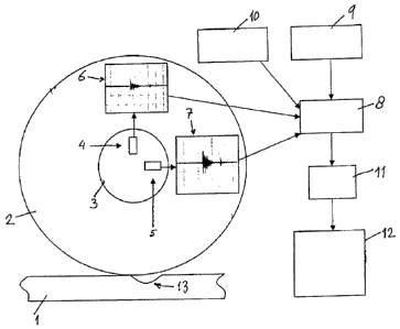
A method and instrumentation for detection of rail defects, in particular rail top defects, in a railway-track by measuring an axle box acceleration signal of a rail vehicle, wherein a longitudinal axle box acceleration signal is used as a measure to detect the occurrence of said rail defects, in particular rail top defects. The method also includes measuring a vertical axle box acceleration signal of said rail vehicle, whereby the longitudinal axle box acceleration signal is used in combination and simultaneously with said vertical axle box acceleration signal. It is further preferred that the longitudinal axle box acceleration signal is used to remove from said vertical axle box acceleration signal a signal-part that relates to vibrations of the rail vehicle's wheelset, including the bearing and axle box (3), and that the axle box acceleration signals are filtered for removing signal-parts contributed by vibrations of the track, including the rail (1), rail pads, fasteners, sleepers, and ballast.


French Abstract

L'invention porte sur un procédé et sur une instrumentation pour la détection de défauts des rails, en particulier des défauts de face supérieure des rails, dans une voie ferrée, par la mesure d'un signal d'accélération d'une boîte d'essieu d'un véhicule ferroviaire, un signal d'accélération longitudinale de la boîte d'essieu étant utilisé comme mesure pour détecter la présence desdits défauts de rails, en particulier des défauts de face supérieure des rails. Le procédé consiste aussi à mesurer un signal d'accélération verticale de la boîte d'essieu dudit véhicule ferroviaire, le signal d'accélération longitudinale de la boîte d'essieu étant utilisé en combinaison et simultanément avec ledit signal d'accélération verticale de la boîte d'essieu. Il est en outre préférable que le signal d'accélération longitudinale de la boîte d'essieu soit utilisé pour extraire dudit signal d'accélération verticale de la boîte d'essieu une partie de signal qui est relative à des vibrations du train de roues du véhicule ferroviaire, lequel train de roues comprend le palier et la boîte d'essieu (3), et que les signaux d'accélération de la boîte d'essieu soient filtrés pour éliminer les parties de signaux qui sont apportés par les vibrations de la voie, y compris le rail (1), les patins de rail, les fixations, les traverses et le ballast.

Claims

Note: Claims are shown in the official language in which they were submitted.


6

CLAIMS

1. A method for detection of rail defects in a
railway-track by measuring an axle box acceleration signal of
a rail vehicle, wherein a longitudinal axle box acceleration
signal is used in combination and simultaneously with a
vertical axle box acceleration signal as a measure to detect
the occurrence of said rail defects, characterized in that the
longitudinal axle box acceleration signal is used to remove
from said vertical axle box acceleration signal a signal-part
that relates to vibrations of the rail vehicle's wheelset,
including the bearing and axle box.
2. A method in accordance with claim 1,
characterized in that the axle box acceleration signals are
filtered for removing signal-parts contributed by vibrations
of the track, including the rail, rail pads, sleepers, and
ballast.

Description

Note: Descriptions are shown in the official language in which they were submitted.


CA 02771003 2012-02-13
WO 2011/019273
PCT/NL2010/050487
1
Method and instrumentation for detection of rail defects, in
particular rail top defects
The invention relates to a method for detection of rail de-
fects, in particular rail top defects, in a railway-track by
measuring an axle box acceleration signal of a rail vehicle.
Rail defects, in particular rail top defects, as referred
to in this document are local short vertical geometrical devia-
tions that may cause impact between the rails of the railway-
track and the rolling wheels of a rail vehicle: Aspects like in-
dentations, differential wear and differential plastic deforma-
tion, inhomogeneous rail material and a defective manufacturing
process of the rails may contribute to this problem. Unless re-
paired a light rail top defect or squat will grow into a moder-
ate defect, and subsequently into a severe defect. Rail fracture
and damages to its fastening, the rail pads, sleepers and bal-
last may also ultimately occur if no remedial action is taken.
From the point of view of railway operation, safety and avail-
ability, rail defects, in particular rail top defects, should be
detected and removed at the earliest possible occasion in order
to prevent their further development into more serious rail de-
fects.
Most commonly rail defects, and squats in particular are
detected by human inspection or by an ultrasonic technique. For
the human inspection inspectors walk along the rail to find the
rail defects, or alternatively inspect photo's or a video record
of the rails. In any case the naked human eye is needed to carry
out the inspection. The ultrasonic inspection technique is only
applicable when the cracks are deeper than approximately 7 mm in
order to allow that the ultrasonic technique can be used for re-
liable detection of such cracks.
It has also been proposed to use eddy-current technology
for detection of rail top defects, and even the use of acoustic
detection has been proposed, however this latter technique is
only applicable for detection of severe rail top defects, which
emit detectable impact noise.
In the article 'A measurement system for quick rail inspec-
tion and effective track maintenance strategy' published in Me-
chanical Systems and Signal Processing 21(2007), pages 1242-
1254, by M. Boccilione et al, instrumentation for measuring lat-

CA 02771003 2012-02-13
W02011/019273
PCIINL2010/050487
2
eral and vertical axle box acceleration of a rail vehicle is
proposed which is usable for detection of defects in a railway-
track.
The measured vertical axle box acceleration of a rail vehi-
cle as is known from said article is usable for the detection of
a severe rail top defect. The measured axle box accelerations at
a rail top defect are basically vibrations stemming from three
sources, being
-1. Vertical vibrations of the track, including those of the
rail, rail pads, fastening, sleepers, ballast etc.
-2. Vertical deformation and relative motion of the wheel and
rail at the defect, and
-3. Vibration of the wheelset, including also those of the bear-
ing and of the axle box.
The above-mentioned vibration source number 2, being the
vertical deformation and relative motion of the wheel and rail
at the defect is the signal that is of interest. For severe rail
defects, in particular rail top defects, the vibration sources 1
and 2 are relatively strong. These sources can however be dis-
tinguished because of their different frequency characteristics.
For less severe rail defects, the vibration signals become less
strong, and vibration source number 3 may become relatively more
dominant than the other sources of vibration. Both aspects con-
tribute to deterioration of the signal-to-noise ratio making it
hard to detect light or moderate rail defects, in particular
rail top defects.
EP-A-1 593 572 discloses a method for identifying locations
along a track at which the wheel of a railway vehicle subjects
the rail along which the vehicle is travelling to longitudinal
forces, comprising the measuring of an acceleration signal of a
wheel of the rail vehicle, wherein a longitudinal acceleration
signal is used in combination and simultaneously with a vertical
acceleration signal.
It is an object of the invention to provide a method for
detection of rail defects, in particular rail top defects, in a
railway-track, by which an accurate and reliable localization of
such rail defects can be realized.
In order to meet the objective of the invention and to re-
alize further advantages as will become apparent hereinafter,
the method for detection of rail defects, in particular rail top

CA 02771003 2016-09-08
3
defects, in accordance with the invention is characterized in
that the longitudinal axle box acceleration signal is used to
remove from said vertical axle box acceleration signal a signal-
part that relates to vibrations of the rail vehicle's wheelset,
including the bearing and axle box.
In a broad aspect, then, the present invention provides a
method for detection of rail defects in a railway-track by meas-
uring an axle box acceleration signal of a rail vehicle, wherein
a longitudinal axle box acceleration signal is used in combina-
tion and simultaneously with a vertical axle box acceleration
signal as a measure to detect the occurrence of said rail de-
fects, characterized in that the longitudinal axle box accelera-
tion signal is used to remove from said vertical axle box accel-
eration signal a signal-part that relates to vibrations of the
rail vehicle's wheelset, including the bearing and axle box.
As compared to the vertical axle box acceleration signal,
the longitudinal axle box acceleration signal is of a relatively
high strength, and moreover this longitudinal signal is a rela-
tively undisturbed signal with a favourable signal-to-noise ra-
tio. The longitudinal axle box acceleration signal is used in
combination and simultaneously with the measured vertical axle
box acceleration signal, in order to subtract from the latter
signal the signal-part that relates to the vibration of the
wheelset, including also those of the bearing and of the axle
box. Due to the earlier mentioned different frequency character-
istics, the vibration signal-of-interest relating to the defor-
mation and relative motion of the wheel and rail at the defect
can be separated from the vertical vibrations of the track. Ac-
cording to the invention it is therefore proposed that the lon-
gitudinal axle box acceleration signal is used to remove from
said vertical axle box acceleration signal the signal-part that
relates to vibrations of the rail vehicle's wheelset, including
the bearing and axle box.
Further from the above it will be clear that according to
the invention it is preferred that the axle box acceleration
signals are filtered for removing signal-parts contributed by

CA 02771003 2016-09-08
3a
vibrations of the track, including the rail, rail pads and fas-
tening, sleepers, and ballast.
It will further be clear that in order to be able to exe-
cute the method of the invention, instrumentation is required
for measuring the axle box acceleration of a rail vehicle, com-
prising at least one accelerometer that is known per se and is
provided on said rail vehicle. This accelerometer is to be
mounted for at least detecting the axle box acceleration in the
longitudinal direction, that is in the direction of the railway-
track. It will be clear that the actual measurement direction of
the accelerometer may deviate some degrees from the exact longi-

CA 02771003 2012-02-13
WO 2011/019273 PCT/NL2010/050487
4
tudinal direction. A suitable type of accelerometer to be used
for this purpose is the Endevco model 7259B lightweight piezo-
accelerometer of the firm Meggitt.
Some measurement results with the application of the in-
strumentation in accordance with the invention are shown in the
drawing of figures 1 and 2 respectively.
In the drawing:
-Figure 1 shows the vertical axle box acceleration signal
in accordance with the prior art;
-Figure 2 shows the longitudinal axle box acceleration sig-
nal in accordance with the invention; and
-figure 3 provides a schematic representation of an instru-
mentation system for measuring axle box acceleration of a rail
vehicle.
In both figures axle box acceleration signals are shown to
represent measured rail irregularities on a revenue track. In
both figures the abscissa is the kilometre-position along the
track, and the ordinate is the measured acceleration signal.
In comparison figures 1 and 2 show that the longitudinal
axle box acceleration signal is more sensitive than the vertical
axle box acceleration signal. There are for instane two clear
peaks in the longitudinal axle box acceleration signal ( figure
2), the smaller peak of which is however hard to be distin-
guished in the signal representing the vertical axle box accel-
eration (figure 1).
Turning now to figure 3 a schematic representation is shown
of a rail 1 of which the rail defects, in particular rail top
defects, are to be measured and localized. One such defect is
schematically represented by reference numeral 13. The measure-
ment of this defect 13 is carried out by employing a rail vehi-
cle having at least one axle box 3 that provides a bearing for a
rail wheel 2. The axle box 3 is provided with both a vertical
accelerometer 4 and a longitudinal accelerometer 5.
The vertical accelerometer 4 provides a vertical accelera-
tion signal as represented by graph 6, which is comparable to
what figure 1 shows.
The longitudinal accelerometer 5 provides a longitudinal
acceleration signal as represented by graph 7,-whiCh is compara-
ble to what figure 2 shows.
The acceleration signals 6, 7 are acquired in a data acqui-

CA 02771003 2012-02-13
WO 2011/019273 PCF/NL2010/050487
sition process by data logger 8. Data logger 8 concurrently
monitors the speed of the rail vehicle by the application of a
tachometer 9, whereas the data logger 8 also logs position data
acquired by GPS system 10.
5 With a sender 11 which is optional the data may be trans-
ferred to a computer system 12 in which data processing and di-
agnosis can be carried out, in order to analyze the nature of
the rail defects and their localisation along the track of the
rail 1.

Representative Drawing
A single figure which represents the drawing illustrating the invention.
Administrative Status

For a clearer understanding of the status of the application/patent presented on this page, the site Disclaimer , as well as the definitions for Patent , Administrative Status , Maintenance Fee  and Payment History  should be consulted.

Administrative Status

Title Date
Forecasted Issue Date 2017-08-29
(86) PCT Filing Date 2010-07-29
(87) PCT Publication Date 2011-02-17
(85) National Entry 2012-02-13
Examination Requested 2015-06-11
(45) Issued 2017-08-29
Deemed Expired 2022-07-29

Abandonment History

There is no abandonment history.

Payment History

Fee Type Anniversary Year Due Date Amount Paid Paid Date
Application Fee $400.00 2012-02-13
Maintenance Fee - Application - New Act 2 2012-07-30 $100.00 2012-07-23
Maintenance Fee - Application - New Act 3 2013-07-29 $100.00 2013-07-26
Maintenance Fee - Application - New Act 4 2014-07-29 $100.00 2014-07-16
Request for Examination $800.00 2015-06-11
Maintenance Fee - Application - New Act 5 2015-07-29 $200.00 2015-07-21
Maintenance Fee - Application - New Act 6 2016-07-29 $200.00 2016-07-22
Final Fee $300.00 2017-06-23
Maintenance Fee - Application - New Act 7 2017-07-31 $200.00 2017-07-17
Maintenance Fee - Patent - New Act 8 2018-07-30 $200.00 2018-07-20
Maintenance Fee - Patent - New Act 9 2019-07-29 $200.00 2019-07-19
Maintenance Fee - Patent - New Act 10 2020-07-29 $250.00 2020-07-15
Maintenance Fee - Patent - New Act 11 2021-07-29 $255.00 2021-07-15
Owners on Record

Note: Records showing the ownership history in alphabetical order.

Current Owners on Record
TECHNISCHE UNIVERSITEIT DELFT
Past Owners on Record
None
Past Owners that do not appear in the "Owners on Record" listing will appear in other documentation within the application.
Documents

To view selected files, please enter reCAPTCHA code :


To view images, click a link in the Document Description column. To download the documents, select one or more checkboxes in the first column and then click the "Download Selected in PDF format (Zip Archive)" or the "Download Selected as Single PDF" button.

List of published and non-published patent-specific documents on the CPD .

If you have any difficulty accessing content, you can call the Client Service Centre at 1-866-997-1936 or send them an e-mail at CIPO Client Service Centre.


Document
Description 
Date
(yyyy-mm-dd) 
Number of pages   Size of Image (KB) 
Abstract 2012-02-13 1 22
Claims 2012-02-13 1 21
Description 2012-02-13 5 213
Representative Drawing 2012-02-13 1 10
Cover Page 2012-04-20 2 48
Drawings 2012-02-13 3 35
Description 2016-09-08 6 224
Claims 2016-09-08 1 19
Final Fee 2017-06-23 1 37
Maintenance Fee Payment 2017-07-17 1 61
Representative Drawing 2017-07-27 1 7
Cover Page 2017-07-27 2 49
PCT 2012-02-13 8 310
Assignment 2012-02-13 3 94
Correspondence 2012-03-26 1 22
Correspondence 2012-04-04 1 36
Fees 2012-07-23 1 47
Fees 2013-07-26 1 46
Fees 2014-07-16 1 53
Request for Examination 2015-06-11 1 40
Maintenance Fee Payment 2015-07-21 1 59
Examiner Requisition 2016-03-22 3 204
Amendment 2016-09-08 6 157
Maintenance Fee Payment 2016-07-22 1 61