Note: Descriptions are shown in the official language in which they were submitted.
CA 02771126 2012-02-14
WO 2011/031716 PCT/US2010/048071
TABLE AND SEATING APPARATUS
This application is being filed on 08 September 2010, as a PCT International
Patent application in the name of Sico Incorporated, a U.S. national
corporation,
applicant for the designation of all countries except the U.S., and
Christopher C.
Dickey, a citizen of the U.S., and Kendall A. Kragenbring, a citizen of the
U.S.,
applicants for the designation of the U.S. only, and claims priority to U.S.
Patent
Application Serial No. 12/557,268 filed on 10 September 2009.
Background of the Invention
Field of the Invention
The present invention is directed to a folding table and seating apparatus and
in particular to a folding table and seating apparatus with a narrow table
that may be
folded for storage and folded to form a seatback with an associated
complementary
bench.
Description of the Prior Art
Folding table and seating devices are well known and have become common
place in large multipurpose use spaces that are utilized at various times as
dining
rooms, meeting halls, lecture rooms and for other uses. In such spaces, it is
often
desirable that multipurpose furniture be used. This furniture normally
includes
tables, chairs, benches and/or stools and related equipment, or table and seat
combinations. Such furniture provides added utility if it folds so that the
assemblies
have a smaller profile for storage and requires a storage base. Folding tables
that
have accompanying stools and benches are well known and provide seating and
table space, but require a relatively small amount of storage space. Examples
of
folding and seating devices include: U.S. Patent No. 2,771,937, U.S. Patent
No.
3,075,809, U.S. Patent No. 3,099,480 and U. S. Patent No. 6,386,628, all
assigned to
SICO Inc., of Edina, Minnesota, the Assignee of the present application.
Although such tables have been successful in providing folding furniture
with associated seating, still further improvements are possible. A
combination
table and seating system is marketed under the trade name ConverTable by SICO,
Inc. and includes a folding table and seating assembly with a bench and a
table top.
1
CA 02771126 2012-02-14
WO 2011/031716 PCT/US2010/048071
In addition, the table top folds to a position wherein the table top forms a
seatback to
the bench. The assembly also folds to a compact storage position wherein the
seatback and seat bottom extends substantially vertically to provide for a
high
degree of nesting, thereby requiring less storage space. The ConverTable table
system also provides for edge to edge mounting when configured as a bench and
table so that a wide table surface is formed by the joined unit with benches
extending along both sides of the tabletop. The bench may include a folding
leg that
retracts in a storage position and is raised so that the frame is supported on
casters.
The assembly may be easily transported from one location to another when
supported only on the casters. Such a table and seating system provides great
benefits as there is relatively small footprint for storage with a high degree
of
nesting. Moreover, the units provide for a table and seating unit as well as
seating
with a seat back. Such flexibility provides great utility.
Although the ConverTable system and other systems have been very
successful in providing multi-use furniture, further improvements are
possible. To
improve the footprint, the framework dimensions could be configured to
maximize
stability while reducing the framework footprint and minimizing any potential
tripping hazards. Moreover, folding should be controlled and eliminate the
possibility of instability due to over folding, while minimizing the risks of
pinching
fingers for operators. The linkage should also be simple and reliable to
facilitate
movement of each of the assemblies between the various positions. The
framework
for such a table and seating system should provide for sturdy and inexpensive
manufacture and also be lightweight so that the system may be easily moved
and/or
lifted.
It can be seen that a new and improved folding table and seating system is
needed. Such a system should provide for safe and easy conversion between a
table
and seating configuration wherein the system has a bench and complementary
tabletop, a seating configuration wherein the system forms a bench and a
complementary seat back and a storage position wherein the elements are folded
to a
substantially vertical position for a high degree of nesting. Moreover, such a
system
should maximize stability while minimizing the footprint. The system should
also
provide for safe controlled movement and folding between the different
2
CA 02771126 2012-02-14
WO 2011/031716 PCT/US2010/048071
configurations. The present invention addresses these as well as other
problems
associated with folding tables and seating systems.
Summary of the Invention
The present invention is directed to a table and seating apparatus that is
foldable between multiple use positions providing different configurations. In
a first
configuration, the system is utilized as a narrow table with a tabletop having
an
associated bench. In a second configuration, the system is utilized as a seat
with a
seat bottom and seat back. In a third configuration, the system sets up for
nesting
for compact storage with the seatback and table portion folded to extend
substantially vertically.
The table and seating system includes a framework at each end of the
assembly. Each of the frameworks has a bottom portion extending transverse to
the
longitudinal direction of the table and seat and risers extending upward. A
first riser
extends to an underside of the tabletop and a second riser extends to a lower
height
to support the seat. The tabletop and seat both include retractable legs that
engage
the floor in one position and are retracted when moved to a second position.
Each of
the frameworks generally is supported on a set of casters for easy transport
in the
storage configuration. The frame is configured so that the lateral portion
extending
beyond the first riser below the tabletop does not extend as far as the end of
a lateral
portion of the frame extending outward below the seat. Such a configuration
reduces any potential tripping hazard while maintaining superior stability and
providing a wide base of support in all configurations.
The tabletop includes a tabletop linkage that retracts the legs below the
tabletop. When the tabletop is in a folded position as a seatback or for
storage, the
tabletop leg at each framework is lifted off the ground and extends above the
lower
portions of the frame. The legs extend with the lower portion extending
slightly
outward at approximately a ten degree angle to act as a guard and as a visual
alert so
that the that the tripping hazard from the frame extending outward is
minimized.
The folding linkage includes a slot in the tabletop frame attached to the
bottom of
the tabletop element forming a sliding link, and folding links extending
between the
leg and associated frame.
3
CA 02771126 2012-02-14
WO 2011/031716 PCT/US2010/048071
In addition, the seat includes a linkage folding the legs upward and the seat
portion to a substantially vertical position against the tabletop and
seatback. The
seat linkage includes a link extending between the seat riser and the leg and
pivots at
the frame and at the top of the leg. Moreover, a stop is positioned against
the pivot
at the seat and frame to prevent instability from over folding of the seat and
tabletop
beyond the intended use positions.
In one embodiment, the seat portion includes a center leg while the end legs
are formed as a tube that extends as a continuous element from one leg to the
other
with the upper horizontal portion of the tube acting as the pivot axis for the
legs.
The assemblies are also fitted with attachments so that the frames below the
tabletop
may be joined to adjacent assemblies to form an extended tabletop having twice
the
width of a single assembly and with bench seating along both sides.
These features of novelty and various other advantages that characterize the
invention are pointed out with particularity in the claims annexed hereto and
forming a part hereof. However, for a better understanding of the invention,
its
advantages, and the objects obtained by its use, reference should be made to
the
drawings that form a further part hereof, and to the accompanying descriptive
matter, in which there is illustrated and described a preferred embodiment of
the
invention.
Brief Description of the Drawings
Referring to the drawings, wherein like reference letters and numerals
indicate corresponding structure throughout the several views:
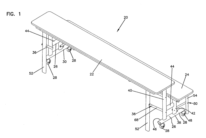
Figure 1 is a perspective view of a folding table and seating apparatus
according to the principles of the present invention configured as a table and
bench;
Figure 2 is an end view of the folding table and seating apparatus shown in
Figure 1;
Figure 3 is a side view of the folding table and seating apparatus shown in
Figure 1;
Figure 4 is an end view of the folding table and seating apparatus shown in
Figure 1 joined with another table and seating apparatus to form a wider table
having opposed benches;
4
CA 02771126 2012-02-14
WO 2011/031716 PCT/US2010/048071
Figure 5 is a perspective view of the folding table and seating apparatus
shown in Figure 1 configured as a seat with a seat back;
Figure 6 is an end view of the folding table and seating apparatus shown in
Figure 5;
Figure 7 is a side view of the folding table and seating apparatus shown in
Figure 5;
Figure 8 is a perspective view of the folding table and seating apparatus
shown in Figure 1 configured for nested storage;
Figure 9 is an end view of the folding table and seating apparatus shown in
Figure 8;
Figure 10 is a side view of the folding table and seating apparatus shown in
Figure 8;
Figure 11 is a perspective detail view of the folding table and seating
apparatus shown in Figure 8 showing the seat leg and pivot;
Figure 12 is a detail view of a stop for the folding linkage for the folding
table and seating apparatus shown in Figure 5;
Figure 13 is a detail view of a leg extending over the frame for the folding
table and seating apparatus shown in Figure 5; and
Figure 14 is a detail view of the folding linkage and offset links for the
folding table and seating apparatus shown in Figure 1.
Detailed Description of the Preferred Embodiment
Referring now to the drawings, and in particular to Figures 1, 5 and 8, there
is shown a table and seating system, generally designated 20. The table and
seating
system 20 may be configured as a table with a bench as shown in Figures 1-4,
as a
bench with a seatback as shown in Figures 5-7 and configured to be nested for
storage as shown in Figures 8-11. The table and seating system 20 generally
includes a tabletop and seatback portion 22 that functions as either a
tabletop or
seatback depending upon the configuration, a seat bottom 24 and support frame
26
at each end of the table and seating system 20. The frame 26 is supported on
conventional casters 28 for easy transport of the table and seating system 20
from
location to location. The folding of the seat bottom 24 is facilitated by a
first linkage
30 while the tabletop and seat back 26 is folded by a second linkage 36. The
5
CA 02771126 2012-02-14
WO 2011/031716 PCT/US2010/048071
tabletop and seatback 22 includes a support frame 32 on the underside of the
tabletop and seatback portion 22 while the underside of the seat bottom
includes a
seat bottom frame 34.
The frame assemblies 26 at each end of the table and seating system 20 each
include a generally horizontal bottom portion 38, a riser 40 extending upward
to the
table and the seatback 22. A second lower seat riser 42 extends up to the
underside
of the seat bottom 24. A horizontal member 44 extends between the risers 40
and 42
to provide added structural integrity and rigidity between the risers 40 and
42. The
frame bottom 38 includes a first portion 46 extending laterally outward beyond
the
riser 40 and a second portion 48 extending laterally outward in an opposite
direction
beyond the seat riser 42. In the embodiment shown, the relative dimensions of
the
first and second portions 46 and 48 of the frame bottom 38 are configured so
that the
second portion 48 of the frame bottom 38 is longer than the first portion 46
of the
frame bottom 38, as shown in Figures 2, 4, 6 and 9. Such a configuration
provides
for superior stability and a wide base for safely supporting the table and
seating
system 20 in all configurations. Moreover, the configuration reduces potential
tripping hazards, as explained further hereinafter.
Referring to Figures 1-4, when configured as a tabletop and bench seat, the
table and seating system 20 includes seat legs 54 and a center seat leg 56
engaging
the ground and supporting the seat bottom 24 and two tabletop legs 52, one at
each
framework assembly 26, engaging the ground and supporting the tabletop 22.
Each
of the tabletop legs 52 mounts to the tabletop frame 32 about a pivot 62 and
also
includes an upper link 64 and lower leg link 68 connecting the leg 52 to the
riser 40
of the frame 26. Moreover, the second linkage 36 includes a slot 60 formed in
the
tabletop frame with a slider 66 at a top of the riser 40 sliding along and
within the
slot 60 to facilitate movement between a position wherein the tabletop and
seatback
portion 22 is substantially vertical, such as when used for storage or as a
seatback,
and a position wherein the tabletop and seatback portion 22 is horizontal,
such as
when used as a tabletop. It can be appreciated that as shown in Figures 5, 6,
8 and 9,
and most clearly in detail in Figure 13, when the tabletop and seatback 22 is
substantially vertical such as in the storage position or when forming a
seatback, the
legs 52 extend substantially over the first portion 46 of the frame bottom 38.
In this
manner, the tripping hazard is reduced as the legs 52 form a guard as well as
6
CA 02771126 2012-02-14
WO 2011/031716 PCT/US2010/048071
providing a visual warning of the presence of the bottom frame 38 extending
outward into a potential walking path. The legs 52 are generally configured so
that
the lower portion extends slightly outward beyond the upper portion at an
angle of
approximately ten degrees. However, other smaller and greater angles between
five
and twenty degrees have also been found to provide superior performance.
The seat bottom 24 is supported on the first linkage 30, which provides for
movement of the seat bottom 24 between a use position and a storage position
independently of movement of the second linkage 36. The first linkage 30
includes
seat legs 54 and a link 70 between the legs 54 and the riser portion 42 of the
frame.
In a preferred embodiment, the legs are formed of a single tube that has a
horizontal
section that acts as a pivot axis 72 between the seat bottom 24 and the legs
54, as
shown most clearly in Figure 11. The seat bottom 24 pivots about the seat
riser 42
at an upper pivot 74 as well as on the leg 54 at a pivot 76. The seat bottom
24 folds
between the use position wherein the seat bottom 24 is substantially
horizontal, as
shown in Figures 1-4, and the generally vertical storage position shown in
Figures 8-
11. It can be appreciated that the seat bottom 24 substantially rests against
the
tabletop 22 in the storage position for improved nesting with other systems
20.
When configure for storage, the table and seating systems 20 provide for a
high
degree of nesting while maintaining superior stability.
As shown most clearly in Figure 4, the table and seating system 20 may be
joined in an edge-to-edge configuration along the edge each tabletop 22
opposite the
seat bottom 24 to form an extended tabletop with benches along opposite sides
of
the tabletop frame 32. Conventional flexible connectors include a male element
84
mounted to an underside of the tabletop 22 and a complementary receiver 86
mounted to the tabletop of an adjacent table and seating system 20. The
connectors
84 and 86 releasably retain the tabletops 22 of the two table and seating
systems 20
pressed against one another. The ability to join the individual table and
seating
systems into a larger table with greater tabletop surface area and benches
along both
sides provides added flexibility and utility to the system 20.
As shown in Figure 12, the first linkage 30 includes a stop 82 engaging the
link 70 that prevents the seat bottom 24 from folding beyond the normal use
positions and over folding of the tabletop and seat back 22 relative to the
seat bottom
24. Therefore, the stop 82 prevents instability and possible shifting of the
seat back
7
CA 02771126 2012-02-14
WO 2011/031716 PCT/US2010/048071
22 and seat bottom 24 if pressure is applied at the wrong point. Although the
stop is
shown mounted on the riser 42 and is engaged by the link 70, other stops
having
different configurations may be utilized.
Referring now to Figure 14, it can be seen that the links 64 and 68 have
offset
portions so that there is improved nesting while the possibility of pinching a
worker's
fingers is decreased. The offset also provides for folding of the various
links of the
second linkage 36 closer together for improved nesting as opposed to having
elements
stacked upon one another within the same path of motion.
It is to be understood, however, that even though numerous characteristics and
advantages of the present invention have been set forth in the foregoing
description,
together with details of the structure and function of the invention, the
disclosure is
illustrative only, and changes may be made in detail, especially in matters of
shape,
size and arrangement of parts within the principles of the invention to the
full extent
indicated by the broad general meaning of the terms in which the appended
claims are
expressed.
8