Note: Descriptions are shown in the official language in which they were submitted.
CA 02771144 2015-09-24
- 1 -
SPINNING DIE ASSEMBLY AND METHOD FOR
FORMING FIBRES USING SAID ASSEMBLY
FIELD OF THE INVENTION
The present invention relates to a die assembly suitable for spinning
filaments and more
particularly to a die assembly comprising a fluid environment around the die
assembly's filament
exit holes.
BACKGROUND OF THE INVENTION
Die assemblies are known in the art. However, known die assemblies fail to
define a controlled
fluid environment around their filament exit holes. As a result, the die
assemblies exhibit
negatives with respect to the properties of the filaments formed by the die
assemblies and/or the
number of filaments capable of being made by the die assemblies.
Accordingly, there is a need for a die assembly that overcomes the negatives
associated with
filaments formed from die assemblies and/or the number of filaments capable of
being formed by
a die assembly.
SUMMARY OF THE INVENTION
The present invention fulfills the need described above by providing a die
assembly that makes
filaments that overcome the negatives associated with filaments formed from
known die
assemblies and/or the number of filaments capable of being formed by a die
assembly.
In one example of the present invention, a die assembly comprising a nozzle
plate comprising a
plurality of filament forming nozzles comprising filament exit holes from
which filaments exit
the filament forming nozzles during operation and wherein the die assembly
further comprises an
enclosure plate that defines an open area around the filament forming nozzles,
is provided.
In another example of the present invention, a die assembly comprising a
nozzle plate
comprising a plurality of filament forming nozzles wherein the filament
forming nozzles
comprise filament exit holes from which filaments are capable of exiting the
filament forming
CA 02771144 2014-09-04
- 2 -
nozzles during operation and wherein the die assembly defines a fluid
environment in fluid
contact with the filament exit holes that maintains greater than 85% of the
effective jet width of
the fluid environment across the filament exit holes, as measured according to
the % Effective
Jet Width Test Method described herein, during operation of the die assembly,
is provided.
In another example of the present invention, a method for forming filaments,
the method
comprising producing filaments from a die assembly comprising a nozzle plate
comprising a
plurality of filament forming nozzles wherein the filament forming nozzles
comprise filament
exit holes from which filaments exit the filament forming nozzles during
operation and wherein
the die assembly further comprises an enclosure plate that defines an open
area around the
filament forming nozzles, is provided.
In yet another example of the present invention, a method for forming
filaments, the method
comprising producing filaments from a die assembly comprising a nozzle plate
comprising a
plurality of filament forming nozzles wherein the filament forming nozzles
comprise filament
exit holes from which filaments exit the filament forming nozzles during
operation and wherein
the die assembly defines a fluid environment in fluid contact with the
filament exit holes that
maintains greater than 85% of the effective jet width of the fluid environment
across the filament
exit holes, as measured according to the % Effective Jet Width Test Method
described herein,
during operation of the die assembly, is provided.
Accordingly, the present invention provides a die assembly suitable for
spinning filaments from
a polymer melt composition that overcomes the negatives associated with known
die assemblies
and a method for spinning filaments from such a die.
BRIEF DESCRIPTION OF THE DRAWINGS
Fig. 1 is an exploded, perspective view of an example of a die assembly in
accordance with the
present invention;
Fig. 2 is a cross-sectional view of the die assembly of Fig. I taken along
line 2-2;
Fig. 3 is a schematic representation of a partial section view of components
of an
example of a die assembly according to the present invention;
CA 02771144 2014-09-04
- 3 -
Fig. 4 is a top plan view of an example of a die assembly according to the
present
invention;
Fig. 5 is a top plan view of another example of a die assembly according to
the present
invention; and
Fig. 6 is a normalized temperature profile graph showing the normalized
temperature
profile of a die assembly according to the present invention compared to a
prior art die
assembly.
DETAILED DESCRIPTION OF THE INVENTION
Die Assembly
The die assembly and method of the present invention are suitable for
producing filaments and
products including such filaments, such as webs and/or fibrous structures. The
die assembly and
method of the present invention may be used to produce different types of
filaments, including
melt-blown fibers, dry spun fibers and/or wet spun fibers. However, the die
assembly and
method are particularly suited for producing filaments from solvent, such as
water, containing
polymer melt compositions. The polymer materials suitable for use in the
solvent containing
polymer melt compositions include materials that are made flowable by
dispersing, suspending
and/or dissolving the material in a solvent.
In one example, the die assembly and method of the present invention are well
suited for
materials that are solvent-soluble, and thus dissolved in a solvent, such as
water, prior to being
forced through the filament forming holes to form filaments. Often it is
desirable to attenuate, or
stretch, the filaments exiting the filament exit holes of the die assembly.
The die assembly of the present invention comprises one or more filament
forming nozzles
comprising one or more filament exit holes from which filaments are capable of
exiting the
filament forming nozzles during operation and wherein the die assembly defines
a fluid
environment in fluid contact with the one or more filament exit holes that
maintains greater than
85% and/or greater than 87% and/or greater than 89% to less than 99% and/or
less than 95%
and/or less than 91% of the effective jet width of the fluid environment
across the one or more
CA 02771144 2014-09-04
- 4 -
filament exit holes, as measured according to the % Effective Jet Width Test
Method described
herein, during operation of the die assembly.
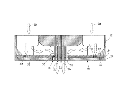
As shown in Figs. 1 and 2, an example of a die assembly 10 in accordance with
the present
invention comprises a nozzle plate 12 comprising one or more filament forming
nozzles 14. The
filament forming nozzles 14 comprise filament exit holes 16. The die assembly
10 defines a fluid
environment 18 in fluid contact with the filament exit holes 16 of the
filament forming nozzles
14. The fluid environment 18 maintains greater than 85% of the effective jet
width of the fluid
environment across the filament exit holes 16 of the filament forming nozzles
14, as measured by
the % Effective Jet Width Test Method, during operation of the die assembly
10.
The die assembly 10 may be designed to supply both the material from which
filaments are
formed and an attenuation medium (such as air, gas or other fluid) for
attenuating the filaments
as they exit the filament exit holes 16 of the filament forming nozzles 14.
The die assembly 10
may be in fluid communication with one or more material sources, such as a
polymer source, that
supplies the material from which filaments are formed to the filament forming
nozzles 14. The
die assembly 10 may include at least one attenuation medium inlet 20 through
which an
attenuation medium may enter the die assembly 10. The attenuation medium inlet
20 may be in
fluid communication with a fluid source, such as a source of air, gas or other
fluid that is used as
an attenuation medium when forming the filaments. The die assembly 10 further
comprises an
attenuation medium exit 22, which is the location at which the attenuation
medium exits the die
assembly 10.
The die assembly 10 may further comprise an enclosure plate 24. The enclosure
plate 24
comprises an open area 26 into which the filament forming nozzles 14 extend.
One or more of
the filament forming nozzles 14 may extend completely through the open area
26. One or more
of the filament forming nozzles 14 may be flush with a surface of the
enclosure plate 24. One or
more of the filament forming nozzles 14 may extend less than completely
through the open area
26. The open area 26 comprises the fluid environment 18 that is in contact
with the filament exit
holes 16. The enclosure plate 24 may direct fluid, such as air, toward the
filament exit holes 16.
In one example, the enclosure plate 24 directs a fluid into the open area 26
comprising the fluid
environment 18 at an angle of greater than 30 and/or greater than 45 and/or
greater than 60
and/or to about 90 to the fluid environment 18.
CA 02771144 2014-09-04
- 5 -
The open area 26 may be of any shape so long as the filament forming nozzles
14 are in contact
with the fluid environment 18.
The enclosure plate 24 further comprises an exterior surface 28 and an
interior surface 30. The
exterior surface 28 is exposed to the external environment. The interior
surface 30 is positioned
inwardly into the die assembly 10 towards the nozzle plate 12. The interior
surface 30 defines a
cavity 32 between the interior surface 30 and an air plate 34 within the die
assembly 10. The
cavity 32 is capable of receiving fluid, such as air, and directing it to the
open area 26. In one
example, the cavity 32 comprises one or more external environment openings,
other than the
open area 26, through which a fluid may enter the cavity 32 from the external
environment and
be directed to the open area 26.
The die assembly 10 may further comprise an air plate 34 as shown in Figs. 1
and 2. The air plate
34 is positioned between the nozzle plate 12 and the enclosure plate 24. The
air plate 34
comprises filament forming nozzle receiving holes 36 through which one or more
of the filament
forming nozzles 14 extend. At least one of the filament forming nozzle
receiving holes 36 are
sized such that an attenuation medium may also pass through the filament
forming nozzle
receiving hole 36 on its way from the attenuation medium inlet 20 to the
attenuation medium exit
22.
In one example, the filament forming nozzle receiving holes 36 are aligned
with the open area 26
such that the attenuation medium exits the filament forming nozzle receiving
holes 36 into the
open area 26.
In another example, the air plate 34 may further comprise one or more first
air holes 38, void of a
filament forming nozzle 14, but adjacent to one or more filament forming
nozzle receiving holes
36. In one example, the first air holes 38 are positioned between one or more
filament forming
nozzle receiving holes 36 and an edge 40 of the air plate 34.
In one example, as shown in Figs. 3 and 4, the filament forming nozzle
receiving holes 36 and
the first air holes 38 are positioned within the open area 26. In one example,
the open area 26
comprises a first gap W1 that defines a minimum distance between an edge of a
first air hole 38
to an edge of the enclosure plate 24. In one example, the first gap WI is less
than 0.020 mm
CA 02771144 2014-09-04
- 6 -
and/or less than 0.018 mm and/or less than 0.015 mm and/or less than 0.010 mm
and/or less than
0.008 mm.
In another example, the open area 26 comprises a second gap W2 that defines a
minimum
distance between an edge of a first air hole 38 to an edge of the enclosure
plate 24. In one
example, the second gap W2 may be the same or different from the first gap Wl.
In another
example, the second gap W2 is less than 0.020 mm and/or less than 0.018 mm
and/or less than
0.015 mm and/or less than 0.010 mm and/or less than 0.008 mm.
Two or more of the first air holes 38 may exhibit the same or different
diameters.
In still another example, the enclosure plate 24 may comprise parallel edges
that define the open
area 26. In yet another example, the enclosure plate 24 at least one edge that
defines a boundary
of the open area 26 that converges toward the filament exit holes 16 of the
filament forming
nozzles 14. In even yet another example, the enclosure plate 24 may comprise
at least one edge
that defines a boundary of the open area 26 that diverges away from the
filament exit holes 16 of
the filament forming nozzles 14.
In another example, the air plate 34 may comprise one or more second air holes
42, void of a
filament forming nozzle 14, through which an attenuation medium may pass. The
one or more
second air holes 42 may be aligned with the cavity 32. The cavity 32 is
capable of directing the
attenuation medium from the second air holes 42 into the open area 26 as shown
by the arrows.
The attenuation medium from the second air holes 42 combines with the
attenuation medium
from the filament forming nozzle receiving holes 36 to form the fluid
environment 18 during
operation of the die assembly 10.
Two or more of the second air holes may exhibit the same or different
diameters.
The arrows shown in Fig. 2 exemplify one or more attenuation medium flow paths
through the
die assembly 10 during operation of the die assembly 10.
The filament forming nozzles 14 may be formed from small metal tubes having
generally
circular cross-sections. Alternatively, the filament exit hole 16 of any
particular filament forming
nozzle 14 may have any cross-sectional shape, may have varying inner and/or
outer effective
CA 02771144 2014-09-04
- 7 -
diameters, may be tapered (e.g. the downstream outer effective diameter is
less than the upstream
outer effective diameter) or beveled and may be made from any suitable
material. The filament
forming nozzles 14 may all have the same upstream inner and/or outer effective
diameter or may
have different upstream inner and/or outer upstream effective diameters.
Likewise, the filament
forming nozzles 14 may all have the same downstream inner and/or outer
effective diameter or
may have different upstream inner and/or outer downstream effective diameters.
Further, the
filament forming nozzles 14 may be the same length or may be different lengths
and/or may be
mounted so as to extend from the nozzle plate 12 different amounts. The
filament forming
nozzles 14 may be made from a separate material that is mounted or otherwise
joined to the
nozzle plate 12 or may be formed in the material making up the nozzle plate 12
itself The
filament forming nozzles 14 may be permanently mounted to the nozzle plate 12
or may be
removable and/or replaceable. Exemplary methods for mounting filament forming
nozzles 14 in
the nozzle plate 12 include, but are not limited to, laser welding, soldering,
gluing, pressure
fitting and brazing.
In one example of the present invention, as shown in Figs. 1 and 2, the
filament forming nozzles
14 are disposed in multiple adjacent rows, wherein each row includes a
multiplicity of filament
forming nozzles 14. Although Figs. 1 and 2 show the filament forming nozzles
14 disposed in
regular rows with equal numbers of filament forming nozzles 14 in each row,
any suitable
number of filament forming nozzles 14 may be in any particular row.
As shown, for example, in Figs. 1 and 2, the die assembly 10 of the present
invention may also
include a spacer plate 44 positioned between the nozzle plate 12 and the air
plate 34. The spacer
plate 44 functions to direct the attenuation medium in a direction generally
parallel to the
filament forming nozzles 14 and to promote flow uniformity, as desired,
throughout the
attenuation area surrounding the filament forming nozzles 14. As such, the
spacer plate 44 has a
spacer plate opening 46 through which at least some of the filament forming
nozzles 14 may
extend.
Even though Figs. 1 and 2 shows the die assembly 10 being made from individual
components,
the die assembly 10 may be a single piece.
CA 02771144 2014-09-04
- 8 -
Method for Forming Filaments
As discussed above, the die assembly of the present invention is suitable for
forming filaments
from materials, especially polymer materials.
In one example of the present invention, a method for forming filaments
comprises the steps of
producing filaments from a die assembly comprising a nozzle plate comprising a
plurality of
filament forming nozzles wherein the filament forming nozzles comprise
filament exit holes
from which filaments exit the filament forming nozzle during operation and
wherein the die
assembly defines a fluid environment in fluid contact with the filament exit
holes that maintains
greater than 85% of the effective jet width of the fluid environment across
the filament exit
holes, as measured according to the % Effective Jet Width Test Method, during
operation of the
die assembly.
The die assembly may comprise a material source that is in fluid communication
with the
filament forming nozzles such that the a material, for example a polymer
material such as starch,
is able to be passed through the filament forming nozzles and exit the
filament exit holes to as
filaments.
As the filaments are exiting the filament exit holes, the filaments are in
fluid contact with the
fluid environment.
The filaments may be subjected to attenuation by an attenuation medium, such
as air, that
contacts the filaments and attenuates the filaments as the filaments move
downstream of the
filament exit holes.
The filaments produced by the die assembly may be collected on a collection
device, such as a
belt or fabric, which may be patterned, to produce a web or fibrous structure.
Test Methods
Unless otherwise specified, all tests described herein including those
described under the
Definitions section and the following test methods are conducted on samples
that have been
conditioned in a conditioned room at a temperature of 73 F 4 F (about 23 C +
2.2 C) and a
CA 02771144 2014-09-04
- 9 -
relative humidity of 50% 10% for 2 hours prior to the test. All tests are
conducted in such
conditioned room.
% Effective Jet Width Test Method
The % effective jet width is determined by measuring the normalized
temperature profile of the
fluid environment across the filament forming exit holes of the filament
forming nozzles of a die
assembly.
A thermocouple probe (1.6 mm diameter) is mounted on a motorized traverse
(Dantec systems,
used with their Laser Doppler equipment). The thermocouple is mounted such
that the tip can
approach the die assembly from downstream to upstream; angling into the fluid
environment in
fluid contact with the filament exit holes of the filament forming nozzles of
the die assembly.
The traverse is used to position the tip of the thermocouple downstream of the
die assembly and
enclosure plate by 1.6 mm.
As shown in Fig. 5, the probe is centered along the narrow, minor axis Am of
the fluid
environment 18 in the open area 26, which is in fluid contact with the
filament exit holes 16 of
the filament forming nozzles of the die assembly 10, and defines a zero
position. The probe
should be at least 5 cm away from the die assembly edges along the longer,
major axis AR of the
fluid environment 18 in the open area 26. The traverse is used to move the
probe across the
narrow, minor axis Am of the fluid environment 18 on 1 mm spacings, far enough
that the
surrounding temperature can be measured along with the main fluid
environment's temperature.
The resulting temperature data is rescaled to yield a normalized temperature
profile. The
maximum and minimum temperature for the dataset is determined. For each
temperature
measurement at position x, a normalized temperature is calculated.
If the maximum temperature corresponds to the fluid environment temperature
then the
normalization formula is as follows:
Tõ ¨ Tinin
TNorrnal, = _________________________________
1 max ¨ Trnin
CA 02771144 2015-09-24
- 10 -
If the minimum temperature corresponds to the fluid environment temperature,
then the
normalization formula is
aTm x Tx
TN ormal, =
'max ¨ Tmin
The normalized temperature data is then plotted with the probe position (x)
shown on the
abscissa and the normalized temperature shown on the ordinate. The effective
jet width of the
fluid environment is then determined graphically by determining the two points
where the fluid
environment achieves 90% of the normalized temperature, an example of such as
graph is shown
in Fig. 6, which shows a normalized temperature profile for both a die
assembly outside the
scope of the present invention labeled "No Enclosure" and a die assembly
within the scope of the
present invention, labeled "With Enclosure". The width is then the difference
in abscissa
positions between these two 90% points.
Once the width is determined, then the % effective jet width is determined.
Effective] etW idth
VoE f f ectivel etWidth = 100 x _______________________
AirPlateWidth
The air plate width is defined as the width between the outermost edge of the
outermost holes in
the air plate, lying along the minor axis of the air plate. The resulting
value is the value that is
reported as the % Effective Jet Width value that the fluid environment
maintains across the
filament exit holes of the filament forming nozzles.
While particular embodiments of the present invention have been illustrated
and described, it
would be obvious to those skilled in the art that various other changes and
modifications can be
made without departing from the invention described herein.