Note: Descriptions are shown in the official language in which they were submitted.
CA 02771270 2012-02-15
WO 2011/(128355 PCT/US201(1/(144-
123
BONDED PATCHES WITH BOND LINE CONTROL
TECHNICAL FIELD
The present disclosure generally relates to bonding
equipment and processes, and deals more particularly with a
method and apparatus for reworking structures using bonded
patches.
BACKGROUND
Adhesives may be used to bond parts and structures in a
wide variety of applications. In
the aircraft industry, for
example, adhesives may be used to bond patches to a structure
such as a skin panel in order to improve, rework and/or repair
an area of the structure. In some cases, the patch and/or the
structure may be formed of composite materials. After
applying a layer of adhesive to the structure and/or the
patch, pressure along with heat is applied to the patch in
order to cure the adhesive and form a strong bond at the patch
and structure.
This bonding process is not easily performed
in the field, and may therefore be normally carried out under
controlled conditions such as, without limitation, within a
maintenance/repair hanger facility where specialized handling
equipment and skilled technicians with knowledge of composites
are available.
The strength and/or longevity of a bonded patch may
depend in part on the thickness of the adhesive, the evenness
1
CA 02771270 2012-02-15
W02011/028355 PCT/US2010/044423
of the adhesive thickness over the area of the patch and/or
the presence of voids or air pockets between the patch and the
structure caused by, without limitation, porosity in the bond.
Bond line thickness and porosity may be controlled to some
degree by controlling the pressure that is applied to the
patch during its installation. However, determining the exact
pressure necessary to achieve a particular bond line thickness
maybe difficult, and in any event, applying this exact
pressure uniformly across the patch may be challenging. Film
type adhesives of constant thickness represent one possible
solution to the problems discussed above, however the use of
film adhesives may not be practical in some applications
because of the special handling that they may require, such
as, without limitation, the need to refrigerate the film until
it is ready for use.
Accordingly, there is a need for a method of bonding a
patch to a structure that allows close control of bond line
thickness over substantially the entire area of the patch, and
which reduces or eliminates porosity in the bond due to voids.
There is also a need for a method of bonding patches to
structures that may be carried out in the field, using an
adhesive that does not require special handling, is not highly
dependent on an installer's skill and which yields consistent,
repeatable results.
2
CA 02771270 2015-07-28
SUMMARY
In accordance with the disclosed embodiments, a method is
provided for bonding patches on structures in which the bond line
or thickness of the bonding adhesive may be controlled over
substantially the entire area of the patch. The
method may not
require a high level of installer skill and may provide consistent,
repeatable results, even when performed in the field. A spacer is
used to aid in allowing adhesive to be applied uniformly over the
area of the patch and to a desired thickness. In one embodiment,
the spacer is placed between the patch and the structure.
Optionally, the spacer may be removed after the adhesive is
applied, or be left between the patch and the structure in order to
limit compaction of the adhesive and thereby maintain a desired
bondline thickness as the patch is being compacted and cured. In
another embodiment, the spacer forms part of the tooling used to
compact the patch against the structure.
Perforations may be
optionally provided in the patch to reduce or eliminate porosity in
the bond by allowing air and/or excess adhesive to escape from the
patch as it is forced against a structure during a patching
operation.
Patch installation may be carried out relatively
quickly in the field using a set of prepackaged, preconfigured
components.
According to one disclosed embodiment, there is provided a
method of reworking an area of a structure, comprising: placing a
spacer over the area, the spacer comprising a screen, the screen
having a thickness substantially the same as diameters of a
plurality of beads, the screen further comprising openings sized to
3
CA 02771270 2015-07-28
allow the plurality of beads to pass through the openings;
thereafter placing a layer of adhesive and the plurality of beads
on the spacer; and placing a patch over the spacer such that the
layer of adhesive is between the spacer and the patch.
According to another disclosed embodiment, a method is
provided of bonding a patch on a structure.
The method includes
placing a spacer on one of the patch and the structure and applying
a layer of viscous bonding adhesive to one of the patch and the
structure.
Application of the adhesive may include using the
spacer to control the thickness of the adhesive layer as the
adhesive is being applied. The method further includes placing the
patch on the structure with the adhesive layer therebetween,
compacting the patch against the structure, and curing the
adhesive.
The method may also include using the spacer to limit
the compaction of the adhesive layer to a preselected thickness as
the patch is compacted against the structure.
The spacer may be
removed after the layer of adhesive has been applied.
According to a further disclosed embodiment, there is
provided a method of bonding a patch on a structure, comprising:
applying a layer of adhesive to an area of the structure; placing a
spacer on the area of the structure, the spacer comprising both a
plurality of beads and a screen, the screen having a first
thickness substantially the same as diameters of the plurality of
beads, the screen further comprising openings sized to allow the
plurality of beads to pass through the openings; using the spacer
to control a second thickness of the layer of adhesive, the layer
of adhesive extending over substantially an entirety of the area;
following placing the spacer, placing a patch on the spacer and
4
CA 02771270 2015-07-28
over the area; and compacting the patch against the layer of
adhesive.
In accordance with a further embodiment, there is provided a
method of reworking a composite aircraft structure in the field,
comprising: preparing an area of the structure to be reworked;
forming a patch including forming perforations in the patch;
applying a layer of adhesive and a plurality of beads to the area
such that said layer of adhesive extends over substantially an
entirety of the area; placing a spacer on the area, the spacer
comprising a screen, the screen having a first thickness
substantially the same as diameters of the plurality of beads, the
screen further comprising openings sized to allow the plurality of
beads to pass through the openings; using the spacer to control a
second thickness of the layer of adhesive to be about the first
thickness of the screen; removing the spacer, wherein beads of the
plurality of beads maintain the second thickness of the layer of
adhesive; applying the patch to the structure over the beads;
removing excess adhesive from the patch; thereafter placing a caul
plate over the patch; placing an anti-caul plate between the caul
plate and the structure such that said anti-caul plate surrounds an
outer periphery of said patch; installing a pressure applicator
over the combination of the patch, the caul plate, and the anti-
caul plate; using the pressure applicator to apply pressure to the
patch through the caul plate, wherein the anti-caul plate limits
the pressure at the periphery of the patch; installing a heat pack
over the patch; and using the heat pack to cure the layer of
adhesive.
5
CA 02771270 2015-07-28
In accordance with a further embodiment, there is provided a
method of reworking an area of a structure, comprising: placing a
layer of viscous bonding adhesive of a substantially uniform
thickness, with at least one spacer, over and around the area, the
at least one spacer having a size that is about equal to said
substantially uniform thickness; placing a patch on the layer of
viscous bonding adhesive and over and around the area; placing an
anti-caul plate around a periphery of the patch, the anti-caul
plate surrounding an entirety of the patch; and pressing the patch
against said viscous bonding adhesive using a caul plate, the caul
plate covering the entirety of the patch and also covering at least
a portion of the anti-caul plate.
In accordance with a further embodiment, there is provided a
method of bonding a patch on structure, comprising: placing the
patch on the structure; placing a layer of bonding adhesive between
the patch and the structure; placing a caul plate over the patch;
pressing the patch against the structure by applying pressure to
the caul plate; and using an anti-caul plate to limit the pressure
applied to a periphery of the patch by the caul plate.
In accordance with a further embodiment, there is provided an
apparatus for adhesively bonding a patch on a structure surface,
comprising: a caul plate adapted to be placed on and apply pressure
to the patch during a bonding operation; and an anti-caul plate
between the caul plate and the structure surface, the anti-caul
plate configured to limit an applied pressure to a periphery of the
patch by the caul plate.
5a
CA 02771270 2015-07-28
In accordance with a further embodiment, there is provided a
method of reworking a composite aircraft structure in the field,
comprising: preparing an area of the structure to be reworked;
forming a patch including forming perforations in the patch;
applying a layer of adhesive to one of the patch and the structure;
controlling a thickness of the adhesive layer by placing a spacer
between the patch and the structure; applying the patch to the
structure; placing a caul plate over the patch; placing an anti-
caul plate between the caul plate and the structure; installing a
pressure applicator over the combination of the patch, the caul
plate and the anti-caul plate; using the pressure applicator to
apply pressure to the patch through the caul plate; using the anti-
caul plate to limit the pressure applied by the caul plate to a
periphery of the patch; installing a heat pack over the patch; and
using the heat pack to cure the adhesive.
The disclosed embodiments satisfy the need for a method and
apparatus for adhesively bonding a patch on a structure that may be
carried out relatively quickly, and allow close control over bond
line thickness while reducing or eliminating porosity in the bond.
The features, functions, and advantages can be achieved
independently in various embodiments of the present disclosure or
may be combined in yet other embodiments in which further details
can be seen with reference to the following description and
drawings.
5b
CA 02771270 2015-07-28
BRIEF DESCRIPTION OF THE ILLUSTRATIONS
The novel features believed characteristic of the
advantageous embodiments are set forth in the appended claims. The
advantageous embodiments, however, as well as a preferred mode of
use, further objectives, and advantages thereof, will best be
understood by reference to the following detailed description of an
advantageous embodiment of the present disclosure when read in
conjunction with the accompanying drawings, wherein:
FIG. 1 is an illustration of a diagram showing an aircraft
manufacturing and service method in accordance with an advantageous
embodiment;
FIG. 2 is an illustration of a diagram showing an aircraft in
which an advantageous embodiment may be implemented;
5c
CA 02771270 2014-04-10
FIG. 2A is an illustration of a functional block diagram
showing the use of a spacer to maintain a desired bondline
thickness between two adhesively bonded parts;
FIG. 3 is an illustration of a diagram showing a bonding
environment in accordance with an advantageous embodiment;
FIG. 4 is an illustration of a diagram showing a cross-
sectional view of application of an adhesive in accordance with an
advantageous embodiment;
FIG. 5 is an illustration of a diagram showing a cross-
sectional view of a structure with a layer of adhesive and beads in
accordance with an advantageous embodiment;
FIG. 6 is an illustration of a diagram showing a mask on a
part in accordance with an advantageous embodiment;
FIG. 7 is an illustration of a diagram showing a part being
prepared for an adhesive in accordance with an advantageous
embodiment;
FIG. 8 is an illustration of a diagram showing application of
an adhesive and beads in accordance with an advantageous
embodiment;
FIG. 9 is an illustration of a diagram showing a part with
adhesive and beads in accordance with an advantageous embodiment;
FIG. 10 is an illustration of a diagram showing application
of adhesive to a part in accordance with an advantageous
embodiment;
FIG. 11 is an illustration of a diagram showing removal of a
screen from a part with adhesive in accordance with an advantageous
embodiment;
6
CA 02771270 2014-04-10
FIG. 12 is an illustration of a diagram showing two parts
bonded to each other in accordance with an advantageous embodiment;
FIG. 13 is an illustration of a flowchart showing a process
for bonding parts in accordance with an advantageous embodiment;
FIG. 14 is an illustration of a flowchart showing a process
for bonding parts in accordance with an advantageous embodiment;
FIG. 15 is an illustration of a plan view of a section of a
structure having an area requiring rework;
FIG. 16 is an illustration of a sectional view taken along
the line 16-16 in FIG. 15;
FIG. 17 is an illustration of a plan view showing a template
having been placed over the area being reworked;
FIG. 18 is an illustration of an isometric view of the patch,
and showing perforations therein;
FIG. 19 is an illustration of a sectional view of the
structure shown in FIG. 15 in which a patch and a layer of adhesive
have been placed over the area requiring rework;
FIG. 20 is an illustration of a view similar to FIG. 19 but
showing a caul plate and an anti-caul plate having been installed
over the patch;
FIG. 21 is an illustration of a top view showing the caul
plate wherein the position of the anti-caul plate and the patch is
indicated in the phantom;
FIG. 22 is an illustration of an exploded view of apparatus
for carrying out the patching method, including a heat pack and a
compactor for applying force to the patch;
7
CA 02771270 2014-04-10
FIG. 23 is an illustration of a flow diagram showing the
steps of a method for reworking a structure using a bonded patch;
FIG. 24 is an illustration of a block diagram showing
components of a pre-packaged kit that may be used to rework a
structure using a bonded patch;
FIG. 25 is an illustration of a perspective view of an
alternate embodiment of a spacer;
FIG. 26 is an illustration of a sectional view taken along
the line 26-26 in FIG. 25;
FIG. 27 is an illustration of a sectional view showing the
use of the spacer of FIG. 25 to maintain bondline thickness during
patch compaction;
FIG. 28 is an illustration of a perspective view of another
embodiment of a spacer;
FIG. 29 is an illustration similar to FIG. 15 but showing a
plurality of the spacers of FIG. 28 having been placed over the
rework area, prior to the application of adhesive;
FIG. 30 is an illustration similar to FIG. 27 but showing the
use of the spacers of FIG. 28 to maintain bondline thickness;
FIG. 31 is an illustration of a perspective view showing the
bottom of a patch having another form of spacer;
FIG. 32 is an illustration similar to FIG 31 but showing a
further form of spacer;
FIG. 33 is an illustration similar to FIG. 30 but showing the
use of the spacer of FIG. 32 to maintain bondline thickness;
FIG. 34 is an illustration similar to FIG. 29 but showing
another embodiment of the spacers;
8
CA 02771270 2014-04-10
FIG. 35 is an illustration of a plan view of a perforated
patch having another form of the spacers applied thereto;
FIG. 36 is an illustration similar to FIG. 35 but showing a
different layout of the spacers on the perforated patch;
FIG. 37 is an illustration of a plan view of a perforated
patch having another form of the spacers formed thereon;
FIG. 38 is an illustration of a sectional view taken along
the line 38-38 in FIG. 37; and,
FIG. 39 is an illustration of a plan view of a perforated
patch having another form of the spacers formed thereon.
DETAILED DESCRIPTION
Referring more particularly to the drawings, embodiments of
the disclosure may be described in the context of aircraft
manufacturing and service method 100 as shown in FIG. 1 and
aircraft 200 as shown in FIG. 2.
Turning first to FIG. 1, a
diagram illustrating an aircraft manufacturing and service method
is depicted in accordance with an advantageous embodiment. During
pre-production, exemplary aircraft manufacturing and service method
100 may include specification and design 102 of aircraft 200 in
FIG. 2 and material procurement 104.
During production, component and subassembly manufacturing
106 and system integration 108 of aircraft 200 in FIG. 2 takes
place.
Thereafter, aircraft 200 in FIG. 2 may go through
certification and delivery 110 in order to be placed in service
112. While
in service by a customer, aircraft 200 in FIG. 2 is
scheduled for routine maintenance and service 114, which may
9
CA 02771270 2014-04-10
include modification, reconfiguration, refurbishment, and other
maintenance or service.
Each of the processes of aircraft manufacturing and service
method 100 may be performed or carried out by a system integrator,
a third party, and/or an operator. In these examples, the operator
may be a customer. For the purposes of this description, a system
integrator may include, without limitation, any number of aircraft
manufacturers and major-system subcontractors; a third party may
include, without limitation, any number of venders, subcontractors,
and suppliers; and an operator may be an airline, leasing company,
military entity, service organization, and so on.
With reference now to FIG. 2, a diagram of an aircraft is
depicted in which an advantageous embodiment may be implemented.
In this example, aircraft 200 is produced by aircraft manufacturing
and service method 100 in FIG. 1 and may include airframe 202 with
a plurality of systems 204 and interior 206. Examples of systems
204 include one or more of propulsion system 208, electrical system
210, hydraulic system 212, and environmental system 214.
Any
number of other systems may be included.
Although an aerospace
example is shown, different advantageous embodiments may be applied
to other industries, such as the automotive industry.
Apparatus and methods embodied herein may be employed during
any one or more of the stages of aircraft manufacturing and service
method 100 in FIG. 1.
For example, components or subassemblies
produced in component and subassembly manufacturing 106 in FIG. 1
may be fabricated or manufactured in a manner similar to
CA 02771270 2014-04-10
components or subassemblies produced while aircraft 200 is in
service 112 in FIG. 1.
Also, one or more apparatus embodiments, method embodiments,
or a combination thereof may be utilized during production stages,
such as component and subassembly manufacturing 106 and system
integration 108 in FIG. 1, for example, without limitation, by
substantially expediting the assembly of or reducing the cost of
aircraft 200.
Similarly, one or more of apparatus embodiments,
method embodiments, or a combination thereof may be utilized while
aircraft 200 is in service 112 or during maintenance and service
114 in FIG. 1.
For example, without limitation, advantageous embodiments may
be used to join parts for aircraft 200 during component and
subassembly manufacturing 106 and/or system integration 108 of
aircraft 200.
Additionally, advantageous embodiments may be
employed during maintenance and service 114 to perform
reconfigurations and/or repairs of aircraft 200.
The different advantageous embodiments recognize and take
into account that current processes for applying adhesive may not
result in an even layer of adhesive being applied to an area in
which bonding is to be performed.
The different advantageous
embodiments also recognize and take into account that the current
processes may not provide a desired thickness for the adhesive
layer even if the adhesive can be applied to form an even layer.
Referring to FIG. 2A, in accordance with the disclosed
embodiments, a method is provided for bonding parts 304, 310
together using a layer of bonding adhesive 332 applied to one or to
11
CA 02771270 2014-04-10
both of the parts 304, 310. The thickness 338 of the adhesive 332,
sometimes also referred to herein as a "bondline", maybe controlled
by placing one or more spacers 315 between the parts 304, 310. As
will be described below, various forms of the spacers 315 are
possible. In one embodiment, a spacer 315 is employed to apply a
uniform layer of adhesive 332 of substantially constant thickness
338 to one or both of the parts 304, 310, and is removed before the
parts 304, 310 are bonded together.
In other embodiments, the
spacer 315 may remain between the parts 304, 310 to aid in
maintaining a constant bondline thickness 338 as the parts 302, 310
are compacted together.
In effect, the spacer 315 limits
compaction of the adhesive 332 as the parts 304, 310 are being
compacted.
Referring to FIG. 3, in one embodiment, the spacer 315 may
comprise a screen 318 and/or beads 334 mixed into the adhesive 332.
The adhesive 332 and a plurality of the beads 334 are applied onto
a surface 328 of a first part 304 through the screen 318 to form a
layer 336 of adhesive 332 and beads 334.
The surface 328 of the
first part 304 with the layer 336 of adhesive 332 and beads 334 is
placed into contact with the surface 340 of the second part 310 to
form an adhesive layer 336 containing beads 334 to form a structure
307. The structure 307 may then be cured.
In these examples, the screen 318 may have a thickness, and
applying the adhesive 332 and the plurality of beads 334 onto a
first surface 328 of the first part 304 through the screen 318 may
result in the layer 336 of adhesive 332 and beads 334 having
substantially the thickness 338 of the screen 318.
12
CA 02771270 2014-04-10
The plurality of beads 334 may have a size capable of causing
a substantially uniform thickness 338 for the layer 336 of adhesive
332 and beads 334 when applied to the first surface 328 of the part
304. The beads 334 may be capable of maintaining the substantially
uniform thickness 338 for the layer of adhesive 332 when joining
parts 304, 310 together.
Pressure applied to one or more parts
304, 310 being joined may not result in an uneven thickness.
Further, the size of the beads 334 and/or the screen 318 may
maintain the thickness 338 under pressure.
In FIG. 3, a bonding environment 300 is depicted in
accordance with an advantageous embodiment.
In this illustrative
example, bonding environment 300 may be used to create structural
bond 302 between part 304 and part 306. Part 304 and part 306 may
form structure 307. In these examples, part 304 and part 306 may
be parts for platform 308. In these examples, platform 308 may be,
for example, aircraft 200 in FIG. 2. Part 304 may take the form of
composite part 305, and part 306 may take the form of composite
part 310.
In these illustrative examples, composite part 305 may be
skin panel 312, although other structures such as, and without
limitation, floor panels, walls, frames, stringers, spars, doors,
and other structures are contemplated. Composite part 310 may be a
patch 314 which may be generally planar before being applied to the
skin panel 312.
After a planar patch 314 is applied to the skin
panel 312, the patch 314 may conform to the surface contour of the
skin panel 312 and thus may become curved in those applications
where the skin panel 312 has a curvature. The patch 314 need not
13
CA 02771270 2014-04-10
be planar; in some embodiments, the patch 314 may be curved or have
contours before application to the skin panel 314. The patch 314
may be uncured or precured. Part 304 and part 306 may be bonded to
each other using bonding system 316.
Bonding system 316 may
include screen 318, template mask 320, applicator 322, caul plate
324, and heat source 326.
Template mask 320 may be placed onto first surface 328 of
composite part 305 to expose area 330.
Screen 318 may then be
placed onto template mask 320. Adhesive 332 and beads 334 may be
applied onto first surface 328 in area 330 through screen 318 to
form layer of adhesive and beads 336. Layer of adhesive and beads
336, when cured, may take the form of bond line 337.
Adhesive 332 and beads 334 may be applied in a number of
different ways. For example, adhesive 332 may be mixed with beads
334 and applied together to form a layer of adhesive and beads 336.
In other advantageous embodiments, adhesive 332 may be applied
through openings 341 in screen 318. Openings 341 may have various
shapes and sizes depending on the particular implementation.
Openings 341 may have a size capable of allowing beads 334 to
pass through openings 341.
Screen 318 also may have other
parameters, such as, for example, without limitation, a screen
weave, an opening between threads, a thread diameter, and/or other
suitable parameters. These parameters may interact with bead size
and adhesive properties, such as thickness, tackiness, surface
tension, viscosity, and/or other adhesive properties.
Thereafter, beads 334 may be added to adhesive 332 on first
surface 328 in area 330 to form layer of adhesive and beads 336.
14
CA 02771270 2014-04-10
In these examples, screen 318 may have thickness 338, which may be
substantially uniform.
As a result, layer of adhesive and beads
336 also may substantially have thickness 338.
Some small excess amount of adhesive 332 with thickness 338
prior to joining, greater than the diameter of beads 334 may be
applied to reduce and/or eliminate potential air gaps that may
occur during joining of composite part 305 and composite part 310.
During joining of part 305 and part 310 parts may be under vacuum
bag pressure or other pressure to squeeze out excess adhesive while
maintaining a uniform bond line with thickness 332 very near a
diameter of beads 334. This ensures adequate fill occurs above all
surface areas. Placing the screen 318 on one of the parts 305, 310
and then applying the adhesive 332 over the part, and optionally
the beads 336, by forcing the adhesive/beads through the screen 318
and troweling off excess adhesive on the screen 318 may help to
control the bondline thickness 338.
Applicator 322 may be used to apply adhesive 332 and/or beads
334 through screen 318 onto first surface 328 of composite part
305.
Applicator 322 may remove excess adhesive 332 and/or beads
334 from screen 318 to form layer of adhesive and beads 336 having
substantially thickness 338.
After layer of adhesive and beads 336 has been formed, screen
318 and template mask 320 may be removed.
Second surface 340 of
composite part 310 may be placed in contact with first surface 328
of composite part 305.
Beads 334 within layer of adhesive and
beads 336 may maintain layer of adhesive and beads 336 with
substantially thickness 338.
Beads 334 may provide a structural
CA 02771270 2014-04-10
element that may maintain thickness 338 at substantially the same
level.
Without beads 334 in layer of adhesive and beads 336,
thickness 338 may become uneven in portions of area 330 after
compaction.
In the different advantageous embodiments, adhesive 332 may
be selected from any adhesive that may be suitable for creating
structural bond 302 between part 304 and part 306.
In the
different advantageous embodiments, adhesive 332 may have a
viscosity such that when screen 318 is removed from the layer of
adhesive and beads 336, the layer of adhesive and beads 336 may
maintain substantially thickness 338.
In one advantageous embodiment, adhesive 332 may be selected
to have the viscosity, tackiness, and surface tension in its
uncured state to allow an appropriate level of flow to occur when
screen 318 is removed. Adhesive 332 with or without beads 334 may
be selected to stick to first surface 328, while maintaining a flow
that will allow adhesive 332 to remain on the structure and reflow
slightly after screen 318 is removed.
Part of the selection of
adhesive 332 takes into account the working time of adhesive 332 so
the properties may be maintained during the application of adhesive
332 and the joining of first surface 328 of composite part 305 and
second surface 340 of composite part 310.
Adhesive 332 may vary depending on the materials for part 304
and part 306.
For example, without limitation, when part 304 and
part 306 takes the form of composite part 305 and composite part
310, adhesive 332 may be an adhesive suitable for composite
components.
16
CA 02771270 2014-04-10
If part 305 and/or part 310 take the form of a metal or
aluminum part, a different type of adhesive may be suitable. The
particular adhesive selected may depend on the material of the
parts being bonded to each other, the strength of the bond desired,
and other suitable factors. Adhesives that may be used include,
for example, without limitation, epoxy adhesives, urethane
adhesives, acrylic adhesives, and other suitable adhesives.
Beads 334 may have size 335. Size 335 may be selected based
on thickness 338 or some other desired thickness.
Size 355 of
beads 334 may be around thickness 338. Further, an amount of beads
334 within layer of adhesive and beads 336 may vary depending on
the particular implementation.
Beads 334 may be comprised of a
material selected from at least one of glass, metal, ceramic,
rubber, and/or some other suitable material.
Beads 334 may be
substantially incompressible in these examples.
This incompressibility may be desirable to avoid reducing
thickness 338. As used herein, the phrase "at least one of", when
used with a list of items, means that different combinations of one
or more of the items may be used and only one of each item in the
list may be needed. For example, "at least one of item A, item B,
and item C" may include, without limitation, item A or item A and
item B. This example also may include item A, item B, and item C,
or item B and item C.
Structure 307 may be cured to create structural bond 302. In
these examples, the curing may be performed for layer of adhesive
and beads 336 to form structural bond 302 between part 304 and part
306.
Curing of structure 307 may be performed using heat source
17
CA 02771270 2014-04-10
326.
Heat source 326 may be, for example, without limitation, a
heat pad, an autoclave, or some other suitable heat source.
In
some advantageous embodiments, caul plate 324 may be placed onto
structure 307 for the curing process.
In these examples, the
different operations performed using bonding system 316 may be
performed manually by human operator 342 and/or automatically by
robotic unit 344.
The illustration of bonding environment 300 in FIG. 3 is not
meant to imply physical or architectural limitations to the manner
in which different advantageous embodiments may be implemented. In
some advantageous embodiments, other components may be used in
addition to, or in place of, the ones illustrated.
In yet other
advantageous embodiments, some components may be unnecessary.
For example, in some advantageous embodiments, the use of
caul plate 324 may be unnecessary during the curing process. In
yet other advantageous embodiments, vent holes may be formed in
composite part 310 when composite part 310 takes the form of a
patch. Vent holes may help squeeze out air trapped within layer of
adhesive and beads 336.
In yet other advantageous embodiments,
structure 307 may be bagged for the curing process. Vacuum bagging
or vacuum bagging and autoclave compaction may help to compress the
bond line to the minimum thickness allowed by beads 334.
As another illustrative example, in some advantageous
embodiments, screen 318 may be placed onto first surface 328 with
template mask 320 being placed over screen 318. In
yet other
advantageous embodiments, template mask 320 may be unnecessary. In
still other advantageous embodiments, adhesive 332 also may be
18
CA 02771270 2014-04-10
placed on second surface 340 of part 306.
In still other
illustrative examples, advantageous embodiments may place an
activator on second surface 340 of part 306.
An activator may
cause adhesive 332 to enter a state in which adhesive 332 cures or
can be cured.
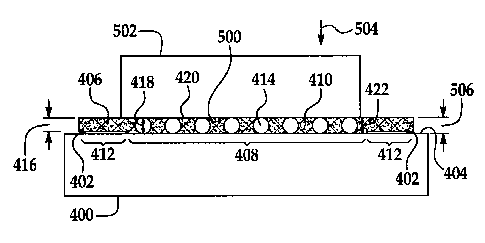
With reference now to FIG. 4, a diagram of a cross-sectional
view of an adhesive is depicted in accordance with an advantageous
embodiment. In this example, part 400 is an example of part 304 in
FIG. 3.
Part 400 may be, for example, without limitation, a skin
panel or some other suitable part. Part 400 may be comprised of a
material such as, for example, without limitation, a composite
material, aluminum, titanium, and/or some other suitable material.
In this example, mask 402 may be placed on surface 404 of part 400.
Screen 406 may be placed onto mask 402. In these examples, mask
402 may expose area 408. Adhesive 410 may be applied onto surface
404 in area 408.
Mask 402 may prevent adhesive 410 from being
applied or deposited onto sections 412 on surface 404 outside of
area 408.
Beads 414 may be mixed with adhesive 410 or applied
separately, depending on the particular implementation.
In these examples, screen 406 may have thickness 416. Beads
414 may have diameter 418.
Diameter 418 may be substantially the
same value as thickness 416 and may be substantially consistent
between different beads in beads 414. With the use of screen 406,
layer of adhesive and beads 420 may be applied to have thickness
422, which may be substantially the same thickness as thickness 416
in area 408.
In other words, thickness 416 of screen 406 may set
19
CA 02771270 2014-04-10
thickness 422 of layer of adhesive 410 and beads 420.
Beads 420
may substantially maintain thickness 422 after screen 406 has been
removed.
Turning next to FIG. 5, a diagram of a cross-sectional view
of a structure with a layer of adhesive and beads is depicted in
accordance with an advantageous embodiment.
In this illustrative
example, surface 404 of part 400 may be placed into contact with
surface 500 of part 502. Part 502 may be, for example, a generally
planar patch or other repair piece for part 400. However, in some
embodiments, as previously mentioned, the part 400 may not be
planar.
In the different advantageous embodiments, force may be
applied on part 502 in the direction of arrow 504.
Beads 414
within layer of adhesive and beads 420 may reduce and/or prevent a
reduction in thickness 422 beyond beads 414 thickness for layer of
adhesive and beads 420. Further, beads 414 may prevent unevenness
within thickness 422 in area 408 of layer of adhesive and beads
420. In these examples, beads 414 may be spherical in shape. Of
course, any shape may be used, depending on the particular
implementation. In these illustrative examples, any shape that may
avoid stacking between beads 414 may be used for beads 414.
In some advantageous embodiments, thickness 422 may be
greater than diameter 418. With this type of implementation, the
layer of adhesive and beads 420 may reduce in value to thickness
506 based on diameter 418 of beads 414, which corresponds to the
final bondline thickness 338 (FIG. 3).
CA 02771270 2014-04-10
With reference now to FIGS. 6-12, diagrams illustrating
application of adhesive and beads to a part are depicted in
accordance with an advantageous embodiment. FIG. 6 is a diagram of
a mask on a part in accordance with an advantageous embodiment.
With reference first to FIG. 6, mask 600 may be placed on surface
602 of part 604.
Mask 600 may expose area 606 on surface 602.
Area 606 may be an area on which adhesive may be applied.
With reference to FIG. 7, a diagram of a part being prepared
for an adhesive is depicted in accordance with an advantageous
embodiment. In this example, screen 700 has been placed over mask
600 on part 604.
As a result, adhesive may only pass through
screen 700 onto surface 602 in area 606 of part 604.
With reference now to FIG. 8, a diagram illustrating
application of an adhesive and beads is depicted in accordance with
an advantageous embodiment. In
this example, adhesive and beads
800 may be applied to surface 602 through screen 700. Adhesive and
beads 800 may only be applied to area 606 because of mask 600.
In FIG. 9, a diagram of a part with adhesive and beads is
depicted in accordance with an advantageous embodiment.
In this
example, layer of adhesive and beads 900 remains after removal of
screen 700 (not shown) and mask 600 (not shown). Part 604 may now
be ready for joining and/or bonding.
With reference now to FIG. 10, a diagram illustrating
application of adhesive to a part is depicted in accordance with an
advantageous embodiment. In
this example, part 1000 has screen
1002 placed on surface 1004. Adhesive 1006 may have been applied
21
CA 02771270 2014-04-10
to surface 1004 through screen 1002.
In this example, adhesive
1006 may not include beads.
Turning to FIG. 11, a diagram illustrating removal of a
screen from a part with adhesive is depicted in accordance with an
advantageous embodiment. In this illustrative example, screen 1002
has been removed from part 1000.
The substantially uniform
adhesive layer 1100 remains on surface 1004. In some advantageous
embodiments, adhesive layer 1100 may take the form of an activator.
With reference now to FIG. 12, a diagram illustrating two
parts bonded to each other is depicted in accordance with an
advantageous embodiment. In this example, part 1000 may be placed
against part 604 and cured to form structural bond 1200 seen as
bond line 1202. Part 1000 and part 604 may be cured using heat and
application of pressure.
The thickness or bond line may be
consistent for structural bond 1200 in this example.
The different operations and features illustrated in FIGS. 6-
12 are not meant to imply limitations to the manner in which
different advantageous embodiments may be implemented.
Some
advantageous embodiments may have other features and/or operations
in addition to, or in place of, the ones illustrated. Further, in
some advantageous embodiments, some of the features and/or
operations may be unnecessary.
For example, in some advantageous
embodiments, adhesive 1006 may be unnecessary for part 1000.
In
yet other advantageous embodiments, screen 700 may be placed onto
surface 602 of part 604 with mask 600 being placed onto screen 700.
With reference now to FIG. 13, a flowchart of a process for
bonding parts is depicted in accordance with an advantageous
22
CA 02771270 2014-04-10
embodiment. The process illustrated in FIG. 13 may be implemented
using a bonding environment such as, for example, bonding
environment 300 in FIG. 3.
The process may begin by placing a mask onto the first
surface of a first part (operation 1300).
The process may then
place a screen onto the mask to form an exposed area on the first
surface of the first part (operation 1302). The process may then
apply an adhesive and a plurality of beads onto the first surface
of the first part through the screen to form a uniform layer of
adhesive and beads (operation 1304). The screen may be used as a
leveling device to achieve the uniform layer of adhesive and beads.
The screen may be removed leaving the uniform layer of adhesives
and beads on the first surface of the first part (operation 1306).
The process may place the first surface of the first part
with the layer of adhesive and beads in contact with the second
surface of a second part to form a structure (operation 1308). The
process may cure the structure (operation 1310), with the process
terminating thereafter.
With reference now to FIG. 14, a flowchart of a process for
bonding parts is depicted in accordance with an advantageous
embodiment. The process illustrated in FIG. 14 may be implemented
using a bonding environment such as, for example, bonding
environment 300 in FIG. 3.
The process may begin by applying an adhesive and a plurality
of beads onto a first surface of a first part to form a layer of
adhesive and beads (operation 1400). The process may then embed a
screen into the layer of adhesive and beads (operation 1402).
23
CA 02771270 2014-04-10
=
Excess of adhesive may be removed from a top of the screen to form
a substantially uniform layer of adhesive and beads (operation
1404).
The screen may then be removed from the substantially
uniform layer of adhesive and beads (operation 1406).
The first surface of the first part with the substantially
uniform layer of adhesive and beads may be placed in contact with
the second surface of a second part to form a structure (operation
1408).
The process may then cure the structure (operation 1410),
with the process terminating thereafter.
The process illustrated in the flowcharts in FIGS. 13 and 14
may be performed in a number of different ways.
In some
advantageous embodiments, other operations may be used in addition
to, or in place of, the ones illustrated. Further, some operations
may be performed simultaneously.
In yet other advantageous
embodiments, some operations may be omitted.
For example, operation 1306 may be omitted to leave the
screen and beads in place when placing the first surface in contact
with the second surface.
In yet other advantageous embodiments,
the layer of adhesive may be placed through the screen without
beads and the screen left in place.
For example, in some
advantageous embodiments, adhesive also may be applied to the
second surface of the second part. In still other embodiments in
which an adhesive is used having two components, the first
component of the adhesive may be applied to the first surface of
the first part, and the second component of the adhesive may be
applied to the second surface of the second part; the two adhesive
24
CA 02771270 2014-04-10
components become mixed when the two parts are placed in face-to-
face contact.
In another example, the adhesive may not include beads. As
another example, the application of the adhesive and the plurality
of beads onto the first surface may be performed by applying a
mixture of the adhesive and the plurality of beads.
In other
advantageous embodiments, the adhesive may be applied to the first
surface.
The beads may then be applied to the first surface
through the screen.
Thus, the different advantageous embodiments provide a method
and apparatus for bonding parts to each other.
The different
advantageous embodiments may provide a capability to create a layer
of adhesive that may have a thickness that is around a
substantially desired value.
Further, the use of beads in the
adhesive may maintain a uniform layer of adhesive with the value
for the desired thickness during and after a compaction pressure is
applied to the parts.
With one or more of the advantageous embodiments,
repeatability may be provided in bonding parts.
In the
illustrative examples, repeatability may include, for example,
without limitation, consistent structural bonds, consistent
strength, consistent design, and certification margins as
structural integrity of parts may be more predictable using
different advantageous embodiments.
These and possible other
features may provide easier and quicker certification of parts
and/or products.
CA 02771270 2014-04-10
Attention is now directed to FIGS. 15 and 16 which illustrate
a composite skin panel 312 such as that found on an airplane. In
this example, the skin panel 312 has a localized area 312a that is
to be reworked.
As used herein, "rework", "reworked" and
"reworking" are used in their broadest sense and are intended to
include, without limitation, rework, repair, restoration,
improvements and modifications that may either return a structure
to its original loading carrying ability and/or specifications, or
improve or increase the performance of the structure in one or more
respects.
However, it should also be noted here that while the
disclosed embodiments illustrate an application involving rework of
an existing skin panel 312, the embodiments may be employed during
the initial manufacturing and assembly of the airplane to form
certain areas of the skin panel 312 and/or to attach one or more
components to the skin panel 312. Thus, as used in the following
description and appended claims, the term "patch" is further
defined to include various forms of parts that are bonded on
another structure, such as components that are bonded to an
airplane structure during the initial manufacturing of the
airplane. In
the illustrated example, the area 312a is a
depression 328a (FIG. 16) which extends down from the outer surface
328 and penetrates through several plies 312b of the skin panel
312. In other applications, the area 312a simply be a deformation
or "dent" in the skin panel 312 that extends down into one or more
of the plies 312b but which does not penetrate the plies. While
the skin panel 312 in the drawings is shown as being substantially
flat, the skin panel 312 may have one or more contours or
26
CA 02771270 2014-04-10
curvatures, in which case a planar patch 314 applied to the skin
panel 312 may conform to the contour or curvature of the skin panel
312.
Also, while the patch 314 shown in the drawings is
substantially planar, in other embodiments, the patch 314 may have
other shapes including but not limited to curves, contours and/or
tapers.
Also, as mentioned previously, the patch 314 may be a
composite that is uncured or precured.
In some situations, such as when the aircraft is required to
remain in service and it is important to avoid schedule
interruptions, it may be necessary to perform the rework "in the
field" outside of a hangar environment where specialized equipment,
special handling and/or skilled maintenance technicians are
available.
For example, it may be necessary to perform the
necessary rework within a limited time while the airplane is parked
at an airport gate in order to avoid a schedule delay. In
accordance with the disclosed embodiments, the needed rework may be
performed relatively quickly by workers such as line mechanics who
may have limited knowledge of composite materials.
The rework may begin by reworking a section 1500 (FIG. 15)
generally surrounding the area 312a requiring rework. Referring to
FIG. 17, a template mask 320 includes a central opening 320a, which
in the illustrated example, is substantially circular and is
coextensive with the rework area 1500, however other shapes of
openings are possible, depending on the application.
The central
opening 320a may serve as both a sanding template during the
preparation of the surface 328 of the skin panel 312, and as a
template for centering a patch 314 (FIG. 18) over the area 312a
27
CA 02771270 2014-04-10
requiring rework.
The template mask 320 further includes ring
shaped, intermittent perforations 320b concentrically surrounding
the central opening 320a. The ring shaped perforations 320b may be
used to mark the outer boundary on the surface 320a where paint is
to be removed from the skin panel 312 as part of the rework
process. Further details of the process for preparing the surface
328 to receive the bonded patch 314 will be discussed below in more
detail.
FIG. 18 illustrates a patch 314 suitable for reworking the
area 312a on the skin panel 312 shown in FIGS. 15-17. In
this
example, the generally planar patch 314 is substantially circular
and includes a plurality of through hole perforations 314a that are
distributed across the patch 314. As will be discussed below, the
perforations 314a may allow the escape of air 1800, as shown by
arrows 1802 from beneath the patch 314 as it is being compacted
against the surface 328 of the skin panel 312 during the patch
installation process. Desirably, each of the perforations 314a may
have a diameter or maximum width "w" that is sufficiently great to
also allow the escape of excess adhesive 1804 from beneath the
patch 314.
Referring now to FIG. 19, the patch 314 may comprise multiple
plies 314b of pre-cured composite materials. In other embodiments,
the patch 314 may be uncured. The patch 314 is bonded to the skin
panel 312 overlying the area 312a to be reworked by a layer of
viscous adhesive 336 forming a bond line 337 having a controlled
thickness 338. As used herein, "viscous" refers to the fact that
the adhesive 336 is spreadable and may flow to some degree as force
28
CA 02771270 2014-04-10
=
is applied to it.
The layer of adhesive 336 may be a fast curing
type of adhesive tailored to the particular application by
selecting predetermined viscosity, tackiness and surface tension
properties in its uncured state.
The viscosity and tackiness of
the adhesive 336 should be such that it will stick to the skin
panel 312 and/or the patch 314, yet remain flowable during
completion of the patch installation process.
The adhesive may include the previously discussed beads 334,
and/or a screen 318 (see FIG. 3). The screen 318 and/or the beads
334 function as a spacer 339 having a thickness that substantially
corresponds to the desired thickness 338 of the bond line 337. In
other embodiments, the screen 318 may be used to apply adhesive 332
to the controlled thickness 338 of the desired bond line 337,
following which the screen 318 may be removed prior to the
application of the patch 314, in which case the remaining beads 334
assist in controlling the thickness 338 of the bond line 337. The
layer 336 of adhesive 332 and beads 334 substantially fill the area
312a being reworked, including the depression 328a (FIG. 16) in the
skin panel 312. In other embodiments, area 312a may be filled with
a suitable filler (not shown) having a composition that is
different than that of the adhesive 332, and then covered with the
adhesive 332.
The amount of adhesive 332 that is applied to the patch 314
and/or the skin panel 312 may vary with the particular application,
including the size and the depth of the area 312a requiring rework.
Where nearly the correct amount of adhesive 332 is applied and is
substantially evenly spread over the rework area 312a, it is
29
CA 02771270 2014-04-10
possible that little or no excess adhesive 332 may be squeezed
through the perforations 314a as the patch 314 is being compacted.
In this case, only air (from air pockets) may be expelled as result
of the adhesive 332 redistributing itself beneath the patch 314 so
as to even out high and low areas of adhesive 332 and fill the air
pockets.
In other cases however, where more than the correct
amount of adhesive 332 is applied, it may be possible to use
observations of the location and/or the amount of excess adhesive
332 that is squeezed out through the perforations 314a as a guide
to determine whether conditions have been met for achieving a
satisfactory bond. In any event, the perforations 314a may assist
in allowing the adhesive 332 to be redistributed beneath the patch
314 in a manner such that the adhesive contacts substantially the
entire area of the patch 314. A rework technician's observations
of excess adhesive 332 being squeezed through the perforations 314a
may be used to assist in confirming that any air pockets have been
substantially eliminated and that the adhesive 332 is in contact
with substantially the entire area of the patch 314.
Attention is now directed to FIGS. 20 and 21 which illustrate
a caul plate 324 placed over the patch 314 in preparation for
compacting the patch 314 down onto the surface 328 of the skin
panel 312. In accordance with the disclosed embodiments, a spacer
in the form of a ring shaped anti-caul plate 2000 is placed between
the caul plate 324 and the surface 328 of the skin panel 312, near
the outer perimeter 2002 of the caul plate 324, so as to support
the caul plate 324 at its outer perimeter 2002. The interior edge
2004 of the anti-caul plate 2002 is radially spaced slightly
CA 02771270 2014-04-10
outside of the outer periphery 2006 of the patch 314.
The anti-
caul plate 2000 has a thickness "t" substantially equal to the
combined thickness 314c of the patch 314 and the desired thickness
338 of the bond line 337. The bottom surface 2012 (FIG. 20) of the
anti-caul plate 2000 engaging the surface 328 of the skin panel 312
is shown as being flat in the illustrated example, however the
bottom surface 2012 may have other shapes or contours that may be
selected to match the shape/contour of the surface 328 of the skin
panel 312.
In the illustrated example, the anti-caul plate 2000
has the shape of a continuous ring (see FIG. 21), however other
shapes are possible. For example, the outer periphery of the anti-
caul plate 2000 may be square.
In any event, it is normally
desirable that the caul plate 324 and the anti-caul plate 2000
having substantially matching foot prints.
Also, in other
embodiments the anti-caul plate 2000 may comprise two or more
contiguous or spaced part sections (not shown) which support the
outer perimeter 2002 of the caul plate 324 at multiple locations
around the patch 314.
The anti-caul plate 2000 functions to react force applied by
the caul plate 324 to the patch 314 near the outer periphery 2006
of the patch 314.
By supporting the outer perimeter 2002 of the
caul plate 324, the anti-caul plate 2000 may reduce or prevent
substantial tipping, slanting and/or bending of the caul plate 324.
As a result of controlling this force at the outer periphery 2006
of the patch 314, the force 2010 applied to the caul plate 324 is
substantially constant over substantially the entire area of the
patch 314.
Consequently, the tendency of the caul plate 324 to
31
CA 02771270 2014-04-10
apply higher forces near the outer periphery 2006 of the patch 314
(due to bending, tipping, slanting, etc.) may be avoided, which
could otherwise result in tapering of the bond line 337 near the
outer periphery 2006 of the patch 314.
Therefore, the thickness
338 of the bond line 337 may remain substantially constant over the
entire area of the patch 314 during the compaction process.
In
addition, the anti-caul plate 2000 acts as a spacer, similar to the
function provided by the screen 318 previously described when left
between the patch 314 and the skin panel 312, which limits
compaction of the adhesive 332 to the desired bondline thickness
338 (FIG. 3). Thus, in one embodiment, the screen 318 can be used
as a first spacer to control the thickness and uniformity of the
adhesive 332 that is applied to the skin panel 312 or other
structure. In those applications where the screen 318 is removed
after application of the layer 336 of adhesive 332, the anti-caul
plate 2000 can be used as a second spacer that limits the
compaction of the adhesive layer 336 during the compaction process
to the desired bondline thickness 338.
FIG. 22 illustrates one embodiment of equipment that may be
used to heat and compact the patch 314 in field applications. A
heat source 326 (FIG. 3) in the form of a heat pack 326a is placed
on top of the caul plate 324 and a compactor 2200 is positioned
over the caul plate 324 and heat pack 326a. The compactor 2200 may
include a series of suction devices 2202 which releasably mount the
compaction device 2200 on the surface 328 of the skin panel 312.
The heat pack 326a applies the heat necessary to cure the adhesive
layer 336 while the compactor 2200 applies the force to the caul
32
CA 02771270 2014-04-10
plate 324 necessary to compact the patch 314 against the surface
328 of the skin panel 312.
Other forms of portable compaction
devices may be employed to apply the necessary compaction force to
the patch 314. For example, a vacuum bag assembly (not shown) may
be assembled over the heat pack 326a, caul plate 324 and patch 314,
which is then sealed to the surface 328 of the skin panel 312.
Alternatively, depending upon the location of the patch 314 on the
skin panel 312, the compaction device may comprise a simple weight
(not shown) that relies on gravity to apply the necessary
compaction force to the patch 314.
Attention is now directed to FIG. 23 which broadly
illustrates the steps of a method of reworking an area 312a on a
structure, such as the previously described composite skin panel
312. The method begins at step 2300 in which a structure, such as
the skin panel 312 is prepared to receive the bonded patch 314.
Preparation of the substructure may involve removing any protruding
material that may prevent the patch 314 from laying flush with the
surface of the structure. The protruding material may be removed,
without limitation, by trimming or sanding.
Step 2300 also
includes placing the template mask 320 (FIG. 17) over the structure
and marking the outer boundaries 320b (FIG. 17) of the area where
paint and other surface coatings may be removed prior to the
bonding process.
The template mask 320 may also be used as a
surface material removal guide during step 2300. Suitable solvents
may be used as part of step 2300 in order to clean the structure
surface of contaminates, including sanding dust.
33
CA 02771270 2014-04-10
Next, at 2302, a suitable patch 314 is prepared in which a
pre-cured doubler (314) is selected and trimmed in size and shape
to fit properly over the rework area 312a.
At step 2304, the
template mask 320 may be placed over the skin surface and held in
place, as by tape.
At step 2306, a screen 318 may be placed over the prepared
surface, overlying the template mask 320, in preparation for the
application of adhesive.
At 2308, optionally, the previously
discussed beads 334 may be mixed into at least one component of the
adhesive 332 and at 2310, the component parts of the adhesive 332
may be mixed together to form a relatively quick drying/curing
bonding adhesive.
In some embodiments, the adhesive 332 may
comprise only one component, in which case the beads 334 may be
mixed into the single component.
Next, at 2312, a layer of the
adhesive 332, optionally containing the beads 334, may be spread
over the prepared skin surface 328 and/or to the patch 314 using an
applicator 322 which may comprise, for example and without
limitation, a toothed trowel (not shown) that may be used to
achieve a predetermined thickness of the adhesive.
In some
applications using a two component adhesive, one of the components
may spread over one of the skin surface 328 and the patch 314, and
the other component may be spread over the other of the skin
surface and the patch 314.
In those applications where the
optional screen 318 is employed, a slightly larger, excess amount
of adhesive than is ultimately needed may be applied in order to
reduce the possibility of air pockets, since the screen 318 may be
used to control the final thickness of the adhesive layer 336. The
34
CA 02771270 2014-04-10
toothed trowel may be used to evenly spread the adhesive over the
structure surface 328 and the patch 314, however, in those
applications where a screen 318 is used, a non-toothed trowel (not
shown) may be used to spread the adhesive 332 over the surface
structure 328 and force it through the screen 318.
The template
mask 320 may be used to control the shape and location of the
adhesive layer 336 applied to the structure surface 328. It should
be noted here that the template mask 320 and the screen 318 may be
combined into as single component and manufactured using well known
photolithographic techniques.
At 2314, the patch 314 is centered over the rework area 312a
using the template mask 320 and the patch 314 is applied by hand to
the structure surface 328, using the template mask 320 as a guide
to locate and center the patch. At 2316, the anti-caul plate 2000
is installed, following which at step 2317, a peel ply (not shown)
may be placed over both the patch 314 and the anti-caul plate 2000.
Next, the caul plate 324 may be installed, as shown at 2318.
At step 2320, a suitable heating source 326, such as the heat
pack 326a (FIG. 22) may be placed over the caul plate 324 and may
be activated. The heat pack 326a may be a self contained package,
such as a chemical heat pack that is activated by breaking a
frangible seal (not shown) and kneading the pack until chemicals
contained in the pack thicken and produce heat by an exothermic
reaction.
In some applications, an adhesive 332 may be employed
that cures at room temperature, in which case the heat pack 326a or
similar heat source may not be necessary.
Next, at step 2322,
pressure is applied to the combination of the heat pack 326a, caul
CA 02771270 2014-04-10
plate 324 and patch 324 by any of several means.
For example, a
vacuum compaction unit 2200 may be placed over the patch 324 and
secured to surface 328 using suction cups 2202.
The compaction
unit 2200 may comprise a vacuum unit which, when activated, draws a
vacuum over the reworked area that results in a downward force
being applied to the caul plate 324 which in turn forces the patch
314 down against the surface 328 of the structure. Alternatively,
a vacuum bag assembly (not shown) may be assembled over the
reworked area and sealed to the surface of the skin panel,
following which a vacuum may be drawn in the bag assembly to apply
pressure to the patch 314.
Finally, as previously mentioned, in
some applications, it may be possible to apply the necessary
pressure to the patch 314 by placing a weight (not shown) on the
caul plate 324.
When the patch 314 is initially applied to the structure
surface 328, air pockets (not shown) may be present either within
the adhesive layer 336, or between the adhesive layer 336 and the
patch 314. One or more of these air pockets may be the result of
there being slight variations in the thickness of the adhesive
layer 336 which creates high or low spots in the adhesive. As the
caul plate 324 applies pressure to the patch 314, the perforations
314a (FIG. 18) allow air, as well as excess adhesive 1804 to escape
or "squeeze-out" from the patch 314, thereby allowing the adhesive
to spread evenly to a substantially uniform, predetermined
thickness 338. The beads 334 and/or the screen 318 act as a spacer
339 (FIGS. 19 and 20) to assist in maintaining the desired bond
line thickness 338.
36
CA 02771270 2014-04-10
As pressure is applied to the patch 314 by the caul plate
324, the anti-caul plate 2000 acts as a spacer that reacts the
force applied near the periphery 2006 of the patch 314 so that the
pressure applied over the entire area of the patch 314 may be
substantially uniform.
Further, as pressure is applied to the
patch 314 during the compaction and curing process, the beads 334
and/or the screen 318 function as a spacer 339 to partially react
the applied force which results in a desired thickness 338 of the
bond line 337.
Attention is now directed to FIG. 24 which illustrates, in
block diagram form, the components of a prepackaged rework kit 2400
that may be used by personnel to perform relatively rapid reworking
of composite skin panels or similar structures in the field. The
kit 24 may include a preconfigured doubler patch 314, a pre-
measured amount of beads 334, a mesh-like screen and/or spacer 318,
a template mask 320, an adhesive applicator such as a toothed
trowel 322, a bonding adhesive 332 including pre-measured amounts
of multiple reactive parts 332a, 332b, a heat pack 326a for use in
curing the adhesive, a compaction device 2200 for applying pressure
to the patch, a paint replacement film 240 that may be used to
replace any paint on the skin surface that was previously removed,
and any number of additional supplies 2402 such as cleaning
supplies, solvents, gloves, release films, etc. that may be
necessary to carry out the rework described above. The kit 2400 may
include more or less components than those described above.
Attention is now directed to FIGS. 25, 26 and 27 which
illustrate an alternate form of spacer 2600 that may be used to
37
CA 02771270 2014-04-10
practice the disclosed method previously described.
The spacer
2600 has a height 2616 substantially corresponding to the desired
bondline thickness 338 (FIG. 27). In this example, the spacer 2600
comprises an outer spacer ring 2602 and an inner spacer ring 2604
connected by circumferentially spaced, radially extending spokes
2606. Although 2 rings 2602, 2604 are shown in the illustrated
example, more than 2 rings may be used, depending on the
application.
It may also be possible to use only a single ring
2602 in some applications.
Each of the rings 2602, 2604 and spokes 2606 have open sides
2612 that allow adhesive (not shown) to freely pass therethrough,
both axially as shown by the arrow 2608, and laterally as shown by
the arrows 2610.
The radial spacing "R÷ between the rings 2602,
2604 may vary with the application.
The spacer 2600 may be
constructed of any suitable material, including but not limited to
metals and polymers, that provides sufficient structural rigidity
such that the spacer 2600 remains substantially non-compressible as
pressure is applied to the patch 314 (FIG. 27) during compaction.
In the illustrated example, the rings 2602, 2604 as well as the
spokes 2606 are formed from wire-like cylindrical elements 2614 of
circular cross section, as shown in FIG. 26, however, other shapes
are possible. As best seen in FIG. 27, the spacer 2600 provides
axial support at multiple locations over the patch 314 which
maintains spacing between the patch 314 and the skin panel 312
corresponding to the desired bondline thickness 338 as the patch
314 is being compacted.
38
CA 02771270 2014-04-10
FIGS. 28, 29 and 30 illustrate another form of spacer 2800
comprising a plurality of individual, elongate spacer elements 2802
each having a height "H" (FIG. 28) substantially corresponding to
the bondline thickness 338.
The spacer elements 2802 may be
flexible and formed of any suitable, substantially non-compressible
material, such as, without limitation, a polymer or a metal. For
example, the individual spacer elements 2802 may be cut from a
length (not shown) of a monofilament fiber. In other embodiments,
each of the spacer elements 2802 may comprise multiple filaments or
fibers gathered or bundled together by any of several known
techniques.
Foe example, the spacer elements 2802 may comprise
carbon fiber tows.
The individual spacer 2802 may be placed in
generally parallel, spaced apart relationship on the skin panel 328
overlying the section 1500 to be reworked. The ends 2804 of each
element may be trimmed to size. It may be desirable, however, to
trim the ends 2804 of the elements 2802 so that they are spaced
inwardly from the outer edge of the rework section 1500. FIG. 30
illustrates the spacer elements 2802 acting a supports interposed
between the patch 314 and the skin panel 312 that maintain the
desired bondline thickness 338 substantially across the entire area
of the patch 314.
Attention is now directed to FIG. 31 which illustrates
another embodiment of a spacer 3100 which may form an integral part
of the patch 314.
The spacer 3100 comprises a plurality of
circumferentially spaced, curved segments 3108 forming spacer
elements arranged in inner and outer rings 3102, 3104 respectively.
Each of the segments 3108 has a height 3110 substantially
39
CA 02771270 2014-04-10
corresponding to the desired bondline thickness 338 (FIG. 30).
Spaced apart openings 3106 between the segments allow adhesive to
flow laterally across the bottom face 3112 of the patch 314 through
the spacer 3100 to achieve a uniform bondline thickness 338 (see
FIG. 30). The individual segments 3108 may comprise substantially
non-compressible inserts that are placed in the patch 314, or
relatively narrow pad-ups integrally formed in the patch 314 in
those cases where the patch 314 is formed of composite materials.
FIG. 32 illustrates still another embodiment of a spacer 3200
comprising a plurality of spacer elements in the form of
substantially non-compressible pins 3202.
Each of the pins 3201
has a height 3204 substantially corresponding to the desired
bondline thickness 338 (FIG. 30). The pins 3202 may be integrated
into the bottom face 3112 of the patch 314 or may be separate from
the patch 314.
The pins may be distributed across the patch 314
either uniformly or non-uniformly, in either a regular or irregular
pattern.
FIG. 33 illustrates the use of the pins 3202 as
individual spacers interposed between the patch 314 and the skin
panel 312 which maintain the desired bondline thickness 338
substantially across the entire area of the patch 314.
FIG. 34 illustrates a further embodiment similar to the
embodiment of FIGS. 28 and 29, but wherein the spacer elements 2802
are arranged in a radial pattern within the rework area 1500,
radiating outwardly from area 312a. In this embodiment, the radial
arrangement of the spacer elements 2802 may aid in channeling the
movement of excess adhesive (not shown) toward the outer edges of
CA 02771270 2014-04-10
the rework area 1550 during compaction where it may be squeezed out
from beneath the patch 314.
FIG. 35 illustrates another embodiment in which spacer
elements 3502 are provided in the form of line shaped protrusions
or bumps that may be formed on a composite patch 3500, which
optionally, may have a plurality of perforations 3504 therein. The
perforations 3504 may allow the escape of air and/or excess
adhesive during the compaction process, as previously described in
connection with FIG. 18.
The spacer elements 3502 may be
relatively short and may be roughly aligned along parallel, spaced
apart axes 3506 extending between the perforations 3504.
The
distance between the spacer elements 3502, their length and their
orientation may vary depending on the application.
In some
applications, the spacer elements 3502 may not be aligned and may
be randomly oriented.
The spacer elements 3502 in FIG. 35 may
comprise an epoxy resin that is molded into the patch 3500, or may
be carbon or glass fibers (tows) reinforced polymer that is cocured
with the patch 3500. The spacer elements 3502 may comprise other
fiber materials such as prepreg tows each formed of many small
diameter monofilament fibers.
The spacer elements 3502 shown in
FIG. 35 may be employed on a patch not haying the perforations
3504.
FIG. 36 shows still another embodiment of a perforated patch
3500 similar to that illustrated in FIG. 35, but showing the spacer
elements 3502 as having random orientations. The line-like spacer
elements 3502 may comprise uncured protrusion material such as a
carbon of glass fiber reinforced polymer that is cocured with the
41
CA 02771270 2015-07-28
patch 3500 when patch 3500 is bonded to another structure (not
shown).
Attention is now directed to FIG. 37 which illustrates a
perforated patch 3500 having spacer elements
in the form of
protrusion bumps 3700 distributed across the face of the patch
3500.
In this embodiment, the spacer elements 3700 may comprise
beads that are partially embedded in the patch 3500 and then cured
with the patch 3500. Alternatively, the spacer elements 3700 may
comprise short lengths of a chopped carbon fiber reinforced polymer
that is cocured with the patch 3500, or which are tacked in an
uncured state to the patch 3500 and then cocured with the adhesive
used to bond the patch 3500 to a structure. While the bumps 3700
are illustrated as having a rounded geometry in the drawings, other
geometries are possible such as, without limitation, a truncated
cone (not shown).
FIG. 39 illustrates still another embodiment in which line-
like spacer elements 3900 similar to those described with reference
to FIGS. 35 and 36 are arranged in a sunburst-like pattern 3902
(only one of which is shown in FIG. 39 for clarity) around each of
the perforations 3504.
The radial arrangement of the spacer
elements 3900 around the perforations 3504 may aid in directing the
movement of excess adhesive toward the perforations 3504 where the
adhesive may squeezed out from beneath the patch 3500 during the
compaction process.
The description of the different advantageous embodiments has
been presented for purposes of illustration and description, and it
is not intended to be exhaustive or limited to the embodiments in
42
CA 02771270 2014-04-10
the form disclosed.
Many modifications and variations will be
apparent to those of ordinary skill in the art.
Although the
different advantageous embodiments have been described with respect
to aircraft, other advantageous embodiments may be applied to other
types of platforms.
For example, without limitation, other advantageous
embodiments may be applied to a mobile platform, a stationary
platform, a land-based structure, an aquatic-based structure, a
space-based structure, and/or some other suitable object. More
specifically, the different advantageous embodiments may be applied
to, for example, without limitation, a submarine, a bus, a
personnel carrier, a tank, a train, an automobile, a spacecraft, a
space station, a satellite, a surface ship, a power plant, a dam, a
manufacturing facility, a building, and/or some other suitable
object. For example, the different advantageous embodiments may be
suitable for bonding wood parts for objects, such as a building, a
boat, and/or some other object that includes wood parts.
Further, different advantageous embodiments may provide
different advantages as compared to other advantageous embodiments.
The embodiment or embodiments selected are chosen and described in
order to best explain the principles of the embodiments, the
practical application, and to enable others of ordinary skill in
the art to understand the disclosure for various embodiments with
various modifications as are suited to the particular use
contemplated.
43