Language selection

Search

Patent 2771416 Summary

Third-party information liability

Some of the information on this Web page has been provided by external sources. The Government of Canada is not responsible for the accuracy, reliability or currency of the information supplied by external sources. Users wishing to rely upon this information should consult directly with the source of the information. Content provided by external sources is not subject to official languages, privacy and accessibility requirements.

Claims and Abstract availability

Any discrepancies in the text and image of the Claims and Abstract are due to differing posting times. Text of the Claims and Abstract are posted:

  • At the time the application is open to public inspection;
  • At the time of issue of the patent (grant).
(12) Patent Application: (11) CA 2771416
(54) English Title: A LIGHTING DEVICE AND A LENS SUITABLE FOR SUCH A LIGHTING DEVICE
(54) French Title: DISPOSITIF D'ECLAIRAGE ET LENTILLE CONCUE POUR LEDIT DISPOSITIF D'ECLAIRAGE
Status: Dead
Bibliographic Data
(51) International Patent Classification (IPC):
  • F21V 7/00 (2006.01)
  • G02B 6/00 (2006.01)
(72) Inventors :
  • HOLTEN, PETRUS ADRIANUS JOSEPHUS (Netherlands (Kingdom of the))
  • TORDINI, GIORGIA (Netherlands (Kingdom of the))
(73) Owners :
  • KONINKLIJKE PHILIPS ELECTRONICS N.V. (Netherlands (Kingdom of the))
(71) Applicants :
  • KONINKLIJKE PHILIPS ELECTRONICS N.V. (Netherlands (Kingdom of the))
(74) Agent: SMART & BIGGAR
(74) Associate agent:
(45) Issued:
(86) PCT Filing Date: 2010-08-12
(87) Open to Public Inspection: 2011-02-24
Availability of licence: N/A
(25) Language of filing: English

Patent Cooperation Treaty (PCT): Yes
(86) PCT Filing Number: PCT/IB2010/053647
(87) International Publication Number: WO2011/021135
(85) National Entry: 2012-02-16

(30) Application Priority Data:
Application No. Country/Territory Date
09168138.7 European Patent Office (EPO) 2009-08-19

Abstracts

English Abstract

A lighting device (1) comprises a light source (2) and a lens (3, 23, 33, 43, 53, 63) positioned in front of the light source (2). The lens (3, 23, 33, 43, 53, 63) is provided with a light entrance surface on a side facing the light source (2) and a light exit surface (14, 38) on a side remote from the light source (2). The lens (3, 23, 33, 43, 53, 63) comprises a number of strip-shaped interconnected elongated light guiding elements (4, 24, 34, 54, 64), of which first ends (7, 27, 37, 57) and spaced apart second ends (5, 25, 35, 55, 65) comprise the light entrance surface and light exit surface, respectively. Light beams emitted by the light source (2) are transmitted by total internal reflection in the elongated light guiding elements (4, 24, 34, 54, 64) from the first ends (7, 27, 37, 57) to the spaced apart seconds ends (5, 25, 35, 55, 65).


French Abstract

La présente invention a trait à un dispositif d?éclairage (1) qui comprend une source lumineuse (2) et une lentille (3, 23, 33, 43, 53, 63) placée devant la source lumineuse (2). La lentille (3, 23, 33, 43, 53, 63) est équipée d?une surface d?entrée de la lumière sur un côté faisant face à la source lumineuse (2) et d?une surface de sortie de la lumière (14, 38) sur un côté distant de la source lumineuse (2). La lentille (3, 23, 33, 43, 53, 63) comprend un certain nombre d?éléments de guidage lumineux allongés interconnectés en forme de bande (4, 24, 34, 54, 64), dont les premières extrémités (7, 27, 37, 57) et les secondes extrémités espacées (5, 25, 35, 55, 65) comprennent la surface d?entrée de la lumière et la surface de sortie de la lumière, respectivement. Les faisceaux lumineux émis par la source lumineuse (2) sont transmis par réflexion interne totale dans les éléments de guidage lumineux allongés (4, 24, 34, 54, 64) des premières extrémités (7, 27, 37, 57) jusqu?aux secondes extrémités éloignées (5, 25, 35, 55, 65).

Claims

Note: Claims are shown in the official language in which they were submitted.


9
CLAIMS:

1. A lighting device (1) comprising a light source (2) and a lens (3, 23, 33,
43,
53, 63) positioned in front of the light source (2), which lens (3, 23, 33,
43, 53, 63) is
provided with a light entrance surface on a side facing the light source (2)
and a light exit
surface (14, 38) on a side remote from the light source (2), characterized in
that the lens (3,
23, 33, 43, 53, 63) comprises a number of strip-shaped interconnected
elongated light guiding
elements (4, 24, 34, 54, 64), of which first ends (7, 27, 37, 57) and spaced
apart second ends
(5, 25, 35, 55, 65) comprise the light entrance surface and light exit
surface, respectively, and
light beams (10, 11) emitted by the light source (2) are transmitted by total
internal reflection
in the elongated light guiding elements (4, 24, 34, 54, 64) from the first
ends (7, 27, 37, 57) to
the spaced apart seconds ends (5, 25, 35, 55, 65).

2. A lighting device (1) according to claim 1, characterized in that at least
the
strip-shaped second ends of the elongated light guiding elements (4, 24, 34,
54, 64) extend
parallel to each other.

3. A lighting device (1) according to claim 1, characterized in that at least
the
second ends of the elongated light guiding elements (4, 24, 34, 54, 64) are
ring-shaped strips
located concentrically with respect to each other.

4. A lighting device (1) according to any one of the preceding claims,
characterized in that at least a part of the elongated light guiding elements
(4, 24, 34, 54, 64)
are at least connected to each other near the first and/or second ends.

5. A lighting device (1) according to any one of the preceding claims,
characterized in that the area of the light exit surface of the lens (3, 23,
33, 43, 53, 63) is at
least 100 times and preferably at least 10,000 times larger than the light
emitting area of the
light source (2).


10
6. A lighting device (1) according to any one of the preceding claims,
characterized in that a light receiving surface (8, 28) of the first end of
the elongated light
guiding element (4, 24, 34, 54, 64) extends substantially perpendicularly to
the light beams of
the light source (2) directed towards said elongated light guiding element (4,
24, 34, 54, 64).
7. A lighting device (1) according to any one of the preceding claims,
characterized in that the light exit surface has an oblique, convex or concave
shape.

8. A lighting device (1) according to any one of the preceding claims,
characterized in that the lens (3, 23, 33, 43, 53, 63) is made of acryl,
polycarbonate or other
transparent material.

9. A lighting device (1) according to any one of the preceding claims,
characterized in that the lens (3, 23, 33, 43, 53, 63) is made by injection
moulding or
extrusion.

10. A lens (3, 23, 33, 43, 53, 63) suitable for use in a lighting device (1)
according
to any one of the preceding claims.
Description

Note: Descriptions are shown in the official language in which they were submitted.


CA 02771416 2012-02-16
WO 2011/021135 PCT/IB2010/053647
1
A lighting device and a lens suitable for such a lighting device

FIELD OF THE INVENTION
The invention relates to a lighting device comprising a light source and a
lens
positioned in front of the light source, which lens is provided with a light
entrance surface on
a side facing the light source and a light exit surface on a side remote from
the light source.
The invention also relates to a lens.
BACKGROUND OF THE INVENTION
Such a lighting device, which is known from EP 2009345 A2, comprises a
lens having a first optical refractive element arranged around a peripheral
edge and a second
optical refractive element centrally located on the lens. Between the light
source, such as a
light emitting diode (LED), and the lens a reflector is located. A forward
emitted portion of
the light of the LED goes directly to the lens whilst a sideward emitted
portion is reflected by
the reflector before it goes to the lens.
A disadvantage of this known lighting device is that the perceived luminance
of the lens is of the same order as the luminance of the light source. In the
case of a high
power LED an intense and blinding light will be emitted by the lighting
device.
The use of such a lighting device with high power LEDs for general indoor
lighting is difficult because of the extreme high luminance of the LED. In
order to avoid
direct exposure of the observer to the high luminance of the LED, luminance
transformers
may be added. However, such luminance transformers have the disadvantage that
they lead to
a decrease of the optical efficiency and an increase of the costs of the
lighting device.
SUMMARY OF THE INVENTION
It is an object of the invention to provide a lighting device with a simple
structure, a relatively high optical efficiency and luminance transformation
to avoid glare.
This object is accomplished with the lighting device according to the
invention
in that the lens comprises a number of strip-shaped interconnected elongated
light guiding
elements, of which first ends and spaced apart second ends comprise the light
entrance
surface and light exit surface, respectively, and light beams emitted by the
light source are


CA 02771416 2012-02-16
WO 2011/021135 PCT/IB2010/053647
2
transmitted by total internal reflection in the elongated light guiding
elements from the first
ends to the spaced apart second ends.
Due to the strip-shaped elongated light guiding elements and the spaced apart
second ends, a lens with an open structure is obtained. Owing to the strip-
shaped elongated
light guiding elements, the length in a first direction from the first end to
the second end is in
the same order or much smaller as the length of the elongated light guiding
elements in a
second direction perpendicular to the first direction. The open structure
provides a relatively
large light exit surface compared to the light entrance surface. The
brightness of the light
source is distributed over a relatively large light exit surface, whereby the
observed
brightness is strongly reduced. Light beams from the light source are
transmitted by total
internal reflection, due to which a high optical efficiency of the lens is
obtained. Lighting
devices with such a lens are applicable for a wide range of indoor and outdoor
applications.
An embodiment of the lighting device according to the invention is
characterized in that at least the strip-shaped second ends of the elongated
light guiding
elements extend parallel to each other.
In this manner, the light exit surface will have a rectangular shape due to
which the light emitted by the lighting device may look similar to the light
emitted by
elongated fluorescent tubes.
Preferably, the elongated light guiding elements extend parallel to each other
from the first ends to the second ends, which makes it possible to manufacture
the lens by
means of extrusion, so that a relatively large length in the second direction
perpendicular to
the first direction from the first end to the second end can be achieved.
A device with such a lens is suitable as a light line for shop lighting or a
light
line for a bus, train or airplane, or tunnel lighting. Such a lens is also
suitable for a waterproof
luminaire, since only the small entrance area where the LED or the LEDs are
located, must
be waterproof, together with both side ends.
Another embodiment of the lighting device according to the invention is
characterized in that at least the second ends of the elongated light guiding
elements are ring-
shaped strips located concentrically with respect to each other.
In this manner, the light exit surface will have a cylindrical shape due to
which
the light emitted by the lighting device may look similar to the light emitted
by incandescent
light bulbs.
Preferably, the elongated light guiding elements are ring-shaped from the
first
ends to the second ends, such that each elongated light guiding element is cup-
shaped.


CA 02771416 2012-02-16
WO 2011/021135 PCT/IB2010/053647
3
A device with such a lens is suitable for home lighting, or as a downlighter
for
office lighting or shop lighting.
Yet another embodiment of the lighting device according to the invention is
characterized in that at least a part of the elongated light guiding elements
are at least
connected to each other near the first and/or second ends.
A continuous light entrance surface and/or exit surface can thus be obtained,
providing the lens with a smooth appearance. The areas where the elongated
light guiding
elements are interconnected are preferably as small as possible to prevent
disturbance of the
total internal reflection in the elongated light guiding elements.
Another embodiment of the lighting device according to the invention is
characterized in that the area of the light exit surface of the lens is at
least 100 times and
preferably at least 10,000 times larger than the light emitting area of the
light source.
Due to the enlargement of the light exit surface with respect to the light
emitting surface of the light source, a decrease in perceived luminance is
obtained.
Depending on the desired luminance, the ratio between light entrance surface
and light
emitting surface is chosen as well as the number and shape of the elongated
light guiding
elements.
Another embodiment of the lighting device according to the invention is
characterized in that a surface of the first end of the elongated light
guiding element extends
substantially perpendicularly to the light beams of the light source directed
towards said
elongated light guiding element.
All light emitted by the light source towards an elongated light guiding
element will enter the elongated light guiding element so that the optical
efficiency will be
optimal.
Yet another embodiment of the lighting device according to the invention is
characterized in that the light exit surface has an oblique, convex or concave
shape.
The shape of the light exit surface further improves the light emitted by the
lighting device, the visual appearance thereof, and determines to a large
extent the beam
pattern emerging from the lighting device. This is of particular interest for
applications in
which beam control is important, for example in automotive headlight systems,
for example
for generating a dim light beam.
Another embodiment of the lighting device according to the invention is
characterized in that the lens is made of acryl, polycarbonate or other
transparent material.
From such materials relatively cheap lenses can easily be produced.


CA 02771416 2012-02-16
WO 2011/021135 PCT/IB2010/053647
4
Another embodiment of the lighting device according to the invention is
characterized in that the lens is made by injection moulding or extrusion.
Such a manufacturing process is relatively easy. In the case of injection
moulding, the lens can be assembled out of several parts to avoid draft angle
problems.
BRIEF DESCRIPTION OF THE DRAWINGS
The invention will be explained in more detail with reference to the drawing,
in which:
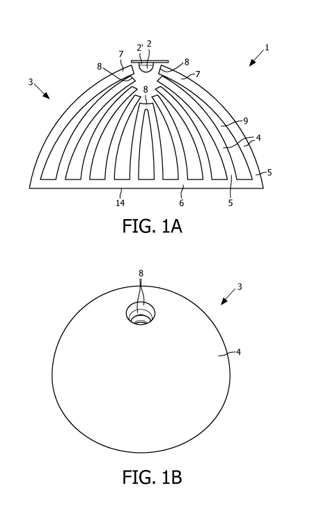
Fig. IA and lB are, respectively, a cross sectional view and a perspective top
view of a first embodiment of the lighting device according to the invention,
Fig. 2 is a cross sectional view of the lens of the lighting device as shown
in
Figure 1, with light beams emitted by the light source and internally
reflected by elongated
light guiding elements of the lens,
Fig. 3 is a perspective view of a second embodiment of the lighting device
according to the invention,
Fig. 4A is a cross section of a third embodiment of the lighting device
according to the invention,
Figs 4B-4D are different embodiments of second ends of the elongated light
guiding elements,
Fig. 5 is a perspective bottom view of the third embodiment of the lighting
device as shown in Figure 4A,
Fig. 6 is a cross section of a fourth embodiment of the lighting device
according to the invention,
Fig. 7 is a cross section of a fifth embodiment of the lighting device
according
to the invention,
Fig. 8 is a cross section of a sixth embodiment of the lighting device
according
to the invention.

DETAILED DESCRIPTION OF EMBODIMENTS
In the Figures, like parts are indicated by the same reference numerals.
Figures IA, lB and 2 show a first embodiment of a lighting device 1
according to the invention. The lighting device 1 comprises a high power LED 2
as light
source and a lens 3. The lens 3 comprises a number of elongated light guiding
elements 4
which are interconnected near spaced apart second ends 5 by means of a plate
6. First ends 7


CA 02771416 2012-02-16
WO 2011/021135 PCT/IB2010/053647
of the elongated light guiding elements are located near the LED 2. The first
ends 7 are
spaced apart, such that the distance between the first ends 7 is much smaller
than the distance
between the second ends 5 at the plate 6. The elongated light guiding elements
4 are cup-
shaped, such that both the first ends 7 and the second ends 5 form ring-shaped
strips. The
5 first ends 7 of the elongated light guiding elements 4 are each provided
with a light receiving
surface 8. The light receiving surfaces 8 of all the elongated light guiding
elements 4 form a
light entrance surface of the lens 3. The light receiving surfaces 8 are
located with respect to
each other in a manner such that all light beams of the LED 2 will enter one
of the light
receiving surfaces 8 and no light beam will enter an opening 9 between the
elongated light
guiding elements 4. Preferably, each light receiving surface 8 extends
substantially
perpendicularly to the light beams entering said light receiving surface 8.
The two centrally
located elongated light guiding elements 4 are connected to each other with
their second
ends 7, however just beyond the first ends 7 the elongated light guiding
elements 4 are
spaced apart. Between the elongated light guiding elements 4 openings 9 are
present which
become wider in a direction away from the LED 2. The strip-shaped elongated
light guiding
elements 4 are relatively long in a direction from the LED 2 towards the plate
6 and in a
circumferential direction. The elongated light guiding elements 4 are curved
and dimensioned
so that a light beam 10, 11 entering the light receiving surface 8 will be
totally reflected
inside the elongated light guiding element 4 by inner and outer surfaces 12,
13 of the
elongated light guiding element 4 until the light beam 10, 11 reaches the
second end 5 of the
elongated light guiding element 4 and leaves the second end 5 through the
light exit
surface 14 of the plate 6.
Due to the elongated light guiding elements 4, the curved form thereof and the
openings 9 between the elongated light guiding elements 4, the light exit
surface 14 of the
plate 6 interconnecting the second ends 5 of the elongated light guiding
elements 4 is much
larger than the light entrance surface as formed by the light receiving
surfaces 8 of the
elongated light guiding elements 4. Preferably, the light exit surface 14 is
at least 100 times
and more preferably at least 10,000 times as large as the light emitting
surface 2' of the LED
2. The light emitting surface 2' of the LED 2 is for example 1x1 mm to 3x3 mm
and the
luminance is for example 107 cd/m2. Preferably, the perceived luminance should
be in the
order of 104 cd/m2 to 5x10⁴ cd/m2. The light exit surface of the lens should
therefore
preferably be in de order of 5x10⁻⁴ m to 10.2 m . The number of elongated
light guiding
elements 4 is preferably at least 3 and at the most 50. The luminance of the
LED 2 is strongly


CA 02771416 2012-02-16
WO 2011/021135 PCT/IB2010/053647
6
fragmented and a much lower luminance is perceived by the observer. However,
due to the
total internal reflection the optical efficiency of the lens 3 is high and
nearly no light is lost.
The lens 3 is made of acryl, polycarbonate or other transparent material and
is
preferably made by injection moulding. It can be made out of several parts to
overcome draft
angle problems during the injection moulding process.
Figure 3 shows a second embodiment of a lens 23 of a lighting device
according to the invention. The lens 23 has a similar cross section as the
lens 3 and as shown
in Figure 1. However, instead of a round shape, the lens 23 has a more
rectangular shape. The
lens 23 comprises a number of strip-shaped elongated light guiding elements 24
extending
parallel to each other. The elongated light guiding elements 24 are
interconnected near
second ends 5 by means of a rectangular plate 26. First ends 27 of the
elongated light guiding
elements 24 are located near a passage 31 into which a number of LEDs 2 can be
positioned
in a row or array. The first ends 27 are spaced apart, the distance between
the first ends 27
being much smaller than the distance between the second ends 25, i.e. at the
location where
the second ends enter the plate 26. The first ends 27 of the elongated light
guiding elements
24 are each provided with a light receiving surface 28, the light receiving
surfaces 28 of all
the elongated light guiding elements 24 thus forming a light entrance surface
of the lens 23.
The light receiving surfaces 28 are located with respect to each other in a
manner such that
all light beams of the LEDs 2 will enter one of the light receiving surfaces
28 and that no
light beam will enter an opening 29 between the elongated light guiding
elements 24.
Light beams of the row of LEDs in the passage 31 will be guided by total
internal reflection through the elongated light guiding elements 24 in a
manner as shown in
Figure 2. The lens 23 can be made by means of extrusion so that a relatively
long lens of for
example 1 metre in the extrusion direction can be obtained. Such a lens can be
used for a
lighting device for a bus, train, airplane or parking garage, for example.
The total light emitting surface of the row or array of LEDs 2 is the sum of
the
light emitting surfaces 2' of all the LEDs 2. Preferably, the light exit
surface of the lens 23 at
the plate 26 is at least 100 times and more preferably at least 10,000 times
as large as the total
light emitting surface of the LEDs 2.
Other shapes of lenses can be made by milling the outer surface of the lens
23.
Figure 4A and 5 show a third embodiment of a lens 33 of a lighting device
according to the invention. The lens 33 comprises cup-shaped curved elongated
light guiding
elements 34. First ends 37 of the elongated light guiding elements 34 are
located against each
other and form a light entrance surface 36. Second ends 35 of the elongated
light guiding


CA 02771416 2012-02-16
WO 2011/021135 PCT/IB2010/053647
7
elements 34 are spaced apart, such that the distance between the second ends
35 is much
larger than the distance between the first ends 37. Between the elongated
light guiding
elements 34 openings 39 are located. Near the second ends 35 the elongated
light guiding
elements 34 are provided with light exit surfaces 38, such that the light exit
surface of the
lens 33 is formed by the area in which the light exit surfaces 38 are located.
The area of the
light entrance surface 36 is much smaller than the area of the light exit
surface 38 of the
lens 33 due to which the perceived luminance of the lighting device is much
lower than the
luminance of the LED 2 positioned opposite the light entrance surface 36. The
second
ends 35 of the elongated light guiding elements 34 can be provided with a
convex light exit
surface 40, a concave light exit surface 41 or an oblique light exit surface
42 as shown in
Figures 4B, 4C, 4D, respectively, to amend the emitted light as desired.
Figure 6 shows a fourth embodiment of a lens 43 of a lighting device
according to the invention. The lens 43 differs from the lens 33 in that the
second ends 35 are
located in a convex plane rather than in a common flat plane.
Figure 7 shows a fifth embodiment of a lens 53 of a lighting device according
to the invention. The lens 53 differs from the lens 33 in that the thickness
of the elongated
light guiding elements 54 near the first ends 57 is larger near the outside of
the lens 54 than
near the inside, whilst the thickness near the second ends 55 of all elongated
light guiding
elements 54 is equal.
Figure 8 shows a sixth embodiment of a lens 63 of a lighting device according
to the invention. The lens 63 differs from the lens 53 in that the second end
65 of the outer
cup-shaped elongated light guiding element 64 is flared so that the light exit
surface 68
thereof faces away from the light exit surfaces 58 of the other elongated
light guiding
elements 54.
It is also possible to manufacture a more rectangular lens, such as shown in
Figure 3 with a cross section as shown in Figure 6, 7 or 8.
It is also possible to extend the outer elongated light guiding elements 34 so
that the second ends are located in a convex plane, a rippled plane or any
differently shaped
plane.
It is also possible to provide the light exit surface of the elongated light
guiding element with a micro structure, such as a frosted structure or
diffusion structure, to
further improve the light distribution.


CA 02771416 2012-02-16
WO 2011/021135 PCT/IB2010/053647
8
It is also possible to connect the elongated light guiding elements to each
other
somewhere between the first and second ends either by a light guiding
material, an opaque
material or a holder.
Preferably, the elongated light guiding elements are rigid. However, it is
also
possible to manufacture flexible elongated light guiding elements so that the
position of the
light exit surface of each elongated light guiding element can be amended as
desired.

Representative Drawing
A single figure which represents the drawing illustrating the invention.
Administrative Status

For a clearer understanding of the status of the application/patent presented on this page, the site Disclaimer , as well as the definitions for Patent , Administrative Status , Maintenance Fee  and Payment History  should be consulted.

Administrative Status

Title Date
Forecasted Issue Date Unavailable
(86) PCT Filing Date 2010-08-12
(87) PCT Publication Date 2011-02-24
(85) National Entry 2012-02-16
Dead Application 2015-08-12

Abandonment History

Abandonment Date Reason Reinstatement Date
2014-08-12 FAILURE TO PAY APPLICATION MAINTENANCE FEE

Payment History

Fee Type Anniversary Year Due Date Amount Paid Paid Date
Application Fee $400.00 2012-02-16
Maintenance Fee - Application - New Act 2 2012-08-13 $100.00 2012-08-01
Maintenance Fee - Application - New Act 3 2013-08-12 $100.00 2013-08-01
Owners on Record

Note: Records showing the ownership history in alphabetical order.

Current Owners on Record
KONINKLIJKE PHILIPS ELECTRONICS N.V.
Past Owners on Record
None
Past Owners that do not appear in the "Owners on Record" listing will appear in other documentation within the application.
Documents

To view selected files, please enter reCAPTCHA code :


To view images, click a link in the Document Description column. To download the documents, select one or more checkboxes in the first column and then click the "Download Selected in PDF format (Zip Archive)" or the "Download Selected as Single PDF" button.

List of published and non-published patent-specific documents on the CPD .

If you have any difficulty accessing content, you can call the Client Service Centre at 1-866-997-1936 or send them an e-mail at CIPO Client Service Centre.


Document
Description 
Date
(yyyy-mm-dd) 
Number of pages   Size of Image (KB) 
Abstract 2012-02-16 2 70
Claims 2012-02-16 2 65
Drawings 2012-02-16 5 83
Description 2012-02-16 8 412
Representative Drawing 2012-02-16 1 11
Cover Page 2012-04-26 2 43
PCT 2012-02-16 7 275
Assignment 2012-02-16 2 67
Prosecution-Amendment 2012-02-16 11 415
Assignment 2012-05-08 9 233
Correspondence 2012-05-16 1 16