Note: Descriptions are shown in the official language in which they were submitted.
CA 02771466 2012-03-19
TITLE OF THE INVENTION
WORK BENCH SUPPORT BRACKET
$ FIELD OF THE INVENTION
The invention relates to an improved support bracket which may be releasably
attached to lumber pieces to form a variety of structures.
BACKGROUND OF THE INVENTION
Support brackets may be used in conjunction with pieces of dimensional lumber
to
form a number of structures. For example, U.S. Patent No. 4,502,565 issued
March 5,
1985 discloses a support bracket, two of which may be releasably attached to
pieces of
dimensional lumber to form a variety of four-legged structures, such as work
benches,
tables, saw horses, scaffolds etc. Each bracket has a pair of opposed,
generally upright
sockets. A piece of dimensional lumber is passed through each of the four
upright
sockets of the two brackets, and a single spring-loaded clamp secures each
piece of
lumber in place to form the legs of the structure. The horizontal displacement
between
the tops of the upright sockets may be adjusted, and one or more planks are
laid atop the
opposed pair of brackets.
Similarly, U.S. Patent No. 5,020,634 issued June 4, 1991 discloses an improved
support bracket. The support bracket further comprises two brace members with
a right-
angled Z shape to brace the sides of one or more planks laid atop the support
brackets.
The shape of the brace members is intended to increase the torsional strength
of the brace
members. The brace members are further notched to straddle the generally
horizontal
sockets of the support bracket. The horizontal sockets are interconnectible
and may
receive opposed ends of a wood extension member.
1
CA 02771466 2012-03-19
The devices of U.S. Patent Nos. 4,502,565 and 5,020,634 have a number of
shortcomings. For example, although a piece of dimensional lumber is secured
to each of
the upright sockets using a spring-loaded clamp to form a leg of the
structure, this clamp
can unexpectedly fail if the leg is kicked or otherwise impacted. This can
result in the leg
sliding within the upright socket, destabilizing the entire structure.
The present invention provides an improved support bracket that overcomes this
and other shortcomings of the prior art.
SUMMARY OF THE INVENTION
The invention provides a work bench support bracket comprising first and
second
opposed, generally upright sockets, first and second interconnectible,
generally horizontal
sockets joined to the first and second generally upright sockets,
respectively, and first and
second clamping sets joined to the first and second generally upright sockets,
respectively. The first and second clamping sets each comprise an upper
releasable
clamp and a fixed lower brace member.
In one aspect of the invention, the upper releasable clamp comprises a grip
pivotably attached to each of the generally upright sockets, with the grip
resiliently urged
in an upward position, a connector, with one end of the connector attached to
the grip, a
joint pivotably attached to another end of the connector, and a handle
pivotably attached
to the joint.
In a further aspect of the invention, the rotation of the handle with respect
to the
connector about the joint is limited. The connector's length may also be less
than the
handle's length.
2
CA 02771466 2012-03-19
In another aspect of the invention, the upper releasable clamp comprises a
grip
pivotably attached to each of the generally upright sockets at an axis of
rotation, with the
grip resiliently urged in an upward position, a handle pivotably attached to
each of the
generally upright sockets at the axis of rotation, and a stopper attached to
the handle for
limiting rotation of the handle with respect to the grip.
In yet another aspect of the invention, each of the generally horizontal
sockets
comprises two sides walls, each of the side walls of the first generally
horizontal socket
comprises one or more first horizontal indentations, and each of the side
walls of the
second generally horizontal socket comprises one or more second horizontal
indentations.
In another aspect of the invention, the first horizontal indentations slide
within the
second horizontal indentations when the first and second generally horizontal
sockets
interconnect.
In one aspect of the invention, one of the side walls of the first horizontal
socket
comprises an aperture and a corresponding one of the side walls of the second
horizontal
socket comprises a pull pin.
The foregoing was intended as a broad summary only and of only some of the
aspects of the invention. It was not intended to define the limits or
requirements of the
invention. Other aspects of the invention will be appreciated by reference to
the detailed
description of the preferred embodiment and to the claims.
BRIEF DESCRIPTION OF THE DRAWINGS
The invention will be described by reference to the detailed description of
the
preferred embodiment and to the drawings thereof, in which:
3
CA 02771466 2012-03-19
Fig. 1 is a top perspective view of a work bench support bracket in accordance
with the preferred embodiment of the invention;
Fig. 2 is a bottom perspective view of the work bench support bracket;
Fig. 3 is a side view of the work bench support bracket;
Fig. 4 is a cross-sectional view taken with respect of line 4-4 of Fig. 3;
Fig. 5 is a cross-sectional view taken with respect of line 5-5 of Fig. 3;
Fig. 6 is a bottom view of the work bench support bracket;
Fig. 7 is a view of the work bench support bracket with wood members
connected;
Fig. 8 is a perspective view of a second embodiment of a portion of the work
bench support; and
Fig. 9 is a side view of the second embodiment of a portion the work bench
support bracket.
DETAILED DESCRIPTION OF THE PREFERRED EMBODIMENT
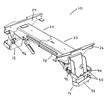
Referring to Figs. 1 and 2, a work bench support bracket 10 in accordance with
the
preferred embodiment comprises first and second opposed, generally upright
sockets 12,
14 for receiving first and second leg members 16, 18 (which may be cut from
readily
available 2" x 4" lumber). Joined to, and extending generally perpendicular to
the
generally upright sockets 12, 14 are first and second telescopically
interconnectible,
generally horizontal sockets 20, 22 for optionally receiving opposed ends of
an extension
4
CA 02771466 2012-03-19
member 28 (which may also be cut from 2" X 4" lumber). The work support
bracket 10
further comprises first and second upwardly extending end members 24, 26
projecting
transversely atop the generally horizontal sockets 20, 22 respectively to
brace the sides of
one or more planks 30 laid atop the generally horizontal sockets 20, 22 (and
atop any
extension member 28 placed between the generally horizontal sockets 20, 22) to
form a
working surface.
A pair of work bench support brackets 10 may be used to form a variety of four-
legged structures, such as work benches, tables, saw horses, scaffolds or the
like, as
generally shown in Fig. 7.
The work bench support bracket 10 further comprises first and second sets of
releasable clamps 32, 34 for releasably securing the first and second leg
members 16, 18
within the generally upright sockets 12, 14 respectively. Each of the two sets
of
releasable clamps 32, 34 comprises an upper clamp 36 and a fixed lower brace
38. The
clamp 36 comprises a grip 40 extending from a pivotal mounting 42 on a shaft
44
pivotally engaged in lugs 46 on the generally upright sockets 12, 14. The grip
40 is
generally U-shaped and extends around the front of the generally upright
sockets 12, 14.
The grip 40 is urged to its upward position, in which it grips leg members 16,
18, by a
spring 48 provided at one of the lugs 46. The grip 40 may further comprise
teeth 50 to
facilitate gripping of the leg members 16, 18.
As best shown in Fig. 6, one end of a connector 52 extends inwardly from the
pivotal mounting 42. The other end of the connector 52 is pivotably attached
to a joint
54. The joint 54 may be formed using a rivet or some other appropriate
connection
mechanism. In one embodiment, the ends of the connector 52 are in a staggered
configuration, such that the joint 54 is closer to the longitudinal middle of
the shaft 44
than the pivotal mounting 42. A handle 56 is also pivotably attached to the
joint 54 and
extends further inwardly. The handle 56 and the connector 52 are able to
rotate relatively
5
CA 02771466 2012-03-19
freely about the joint 54 to a maximum angle. In one embodiment, this maximum
angle
is approximately 2200, although other maximum angles may also be possible.
Further
rotation is prevented by the presence of a limiter or stopper 53 in the joint
54. The degree
of the freedom of rotation of the handle 56 should be such that, when the
first and second
leg members 16, 18 are not present, the handle does not impede placement of
the
generally upright sockets 12, 14 on a flat surface to better facilitate
assembly and
disassembly. The length of the handle 56 should be greater than the length of
the
connector 52. Because of the staggered configuration of the connector 52, the
handle 56
lies substantially underneath the horizontal sockets 20, 22. In the embodiment
shown in
Fig. 6, the spring 48 is located on the end of the spring 44 closest to the
handle 56.
The brace 38 is generally U-shaped and extends around the front of the
generally
upright sockets 12, 14. The brace 38 may be attached to the generally upright
sockets 12,
14 by welding, although other fastening mechanisms may be used as well. The
brace 38
may also comprise teeth (not shown) to facilitate gipping of the leg members
16, 18. In
another embodiment, the brace 38 may be integrally formed with the side walls
of the
generally upright sockets 12, 14. In yet another embodiment, the brace 38 need
not span
the entire width of the generally upright sockets 12, 14. The brace 38
provides a
secondary surface of contact to the leg members 16, 18.
Operation of the sets of releasable clamps 32, 34 will now be described. In
particular, operation of the first set of releasable clamps 32 will be
described, although it
is to be understood that the second set of releasable clamps 34 operates in a
similar
manner. When at rest, the grip 40 is urged to its upward position because of
the spring
48. As a result, the connector 52 extends at an angle downwardly from the
pivotal
mounting 42. Because of the joint 54 and the effect of gravity, the handle 56
will extend
substantially vertically downward from the joint 54.
6
CA 02771466 2012-03-19
In order to insert the first leg member 16 into the first generally upright
socket 12,
the grip 40 must be positioned away from its upward position in order to allow
the first
leg member 16 to slide into place within the first generally upright socket
12. In order to
do so, the handle 56 is moved upward from its substantially vertical position.
As it is
moved upward, the handle 56 rotates about the joint 54 until the angle between
the handle
56 and the connector 52 reaches approximately 2200, at which time further
rotation about
the joint 54 is prevented. Further upward movement of the handle 56 will now
cause the
connector 52 to rotate upwards (with respect to the pivotal mounting 42),
which in turn
results in the grip 40 rotating downwards (with respect to the pivotal
mounting 42)
against the spring 48. When the grip 40 has moved sufficiently away from its
upward
position, the first leg member 16 may be inserted into the first generally
upright socket
12. The first leg member 16 will also slide within the brace 38.
After the first leg member 16 is in place within the first generally upright
socket
12, the handle 56 may be released. The spring 48 urges the grip 40 back
towards its
upward position. The teeth 50 on the grip 40 will contact the side of the
first leg member
16 and hold it in place within the first generally upright socket 12. As the
grip 40 moves
back towards its upward position, the connector 52 will rotate downward about
the
pivotal mounting 42. The handle 56 will also rotate downward about the joint
54 and
will again assume a substantially vertical position.
If the first leg member 16 is to be removed from the first generally upright
socket
12, the handle 56 is again moved upward from its substantially vertical
position. As it is
moved upward, the handle 56 rotates about the joint 54 until the angle between
the handle
56 and the connector 52 reaches approximately 220 , at which time further
rotation about
the joint 54 is prevented. Further upward movement of the handle 56 will now
cause the
connector 52 to rotate upwards (with respect to the pivotal mounting 42),
which in turn
results in the grip 40 rotating downwards (with respect to the pivotal
mounting 42)
against the spring 48 and losing contact with the side of the first leg member
16. When
7
CA 02771466 2012-03-19
the grip 40 has moved sufficiently away from its upward position, the first
leg member 16
may be slid out of the brace 38 and out of the first generally upright socket
12.
The presence of the joint 54 causes the handle 56 to rotate downward to a
substantially vertical position when the sets of releasable clamps 32, 34 are
at rest. This
makes it more difficult for a person to accidentally knock the handle 56 and
cause the
grip 40 to unexpectedly release the leg members 16, 18 from the generally
upright
sockets 16, 18. In order to do so would require rotation of the handle 56
sufficient to
achieve an approximately 220' angle with the connector 52, plus a further
rotation about
the pivotal mounting 42. This would be difficult to do with an accidental
impact on the
handle 56. Because of the relative lengths of the handle 56 and the connector
52, in order
to move the grip 40 using only the connector 52 (without the assistance of the
handle 56)
would require a great deal of torque. Furthermore, because the handle 56 is
located
substantially underneath the horizontal sockets 20, 22, there is less
likelihood of an
accidental impact on the handle 56.
The presence of the brace 38 provides an additional surface of contact and
provides additional safety. Without the brace 38, the leg members 16, 18 would
be held
in place against the generally upright sockets 12, 14 by the grip 40 only.
However, any
accidental impact on the leg members 16, 18 could result in the leg members
16, 18
shifting or rotating about the grip 40. This may result in the associated
structure
collapsing. By having a brace 38, the likelihood of such movement is reduced,
since the
brace 38 provides an additional surface of contact, with additional stability.
Referring to Figs. 8 and 9, in an alternative embodiment, the connector 52 is
not
used. Instead, in support bracket 100, grip 400 extends from pivotal mounting
420 on
shaft 440 pivotally engaged in lugs 460 on generally upright sockets 120, 140.
The grip
400 is urged to its upward position, in which it grips leg members by a spring
480.
Handle 560 is pivotably attached to pivotal mounting 420 and is able to rotate
about the
8
CA 02771466 2012-03-19
pivotal mounting 420 with respect to the grip 400. Stopper 530 attached to the
handle
560 limits the maximum amount of rotation. In this embodiment, spring 480 is
located
on the shaft 440 on the opposite end as the handle 560. Figs. 8 and 9 show
half of the
support bracket 100, but the other half would be substantially a mirror image.
Referring to Figs. 3 to 5, the first horizontal socket 20 comprises a first
upper
surface 58 and first vertical surfaces 60. The second horizontal socket 22
comprises a
second upper surface 62 and second vertical surfaces 64. The first vertical
surfaces 60 of
the first horizontal socket 20 comprise one or more first horizontal
indentations 66. One
or more aligned and corresponding second horizontal indentations 68 are formed
on the
second vertical surfaces 64 of the second horizontal socket 22 such that the
first
horizontal indentations 66 slide within the second horizontal indentations 68
when the
first horizontal socket 20 and the second horizontal socket 22 telescope, as
best shown in
Figs. 4 and 5. In Figs. 3 to 5, each of the first vertical surfaces 60 has one
first horizontal
indentation 66, and each of the second vertical surfaces 64 has one second
horizontal
indentation 68.
The horizontal indentations 66, 68 may be formed by stamping and may extend
either for a substantial portion of the length of the horizontal sockets 20,
22. In Figs. 3 to
5, the horizontal indentations 66, 68 extend from the open end of the
horizontal sockets
20, 22. Each of the horizontal indentations 66, 68 has a convex portion on one
side and a
corresponding concave portion on the other side of the vertical surfaces 60,
64 of the
horizontal sockets 20, 22. The horizontal indentations 66, 68 serve to
increase the
strength and rigidity of the horizontal sockets 20, 22, both alone and when
telescopically
connected.
As discussed above, the horizontal sockets 20, 22 telescope and may slide
within
one another. An aperture 70 is provided on one of the vertical surfaces 60 of
the first
horizontal socket 20. A pull pin 72 is provided on the corresponding vertical
surface 64
9
CA 02771466 2012-03-19
of the second horizontal socket 22. When the horizontal sockets 20, 22
telescope and
when the aperture 70 is aligned with the push pin 72, the pull pin 72 will be
biased
toward its extended position, at which time it will pass through the aperture
70. This
prevents any further movement of the horizontal sockets 20, 22 with respect to
each other
and locks their positions in place. The pull pin 72 can be deactivated by
pulling on it in
order to allow the horizontal sockets 20, 22 to again telescope.
It will be appreciated by those skilled in the art that the preferred
embodiment has
been described in some detail but that certain modifications may be practiced
without
departing from the principles of the invention.