Note: Descriptions are shown in the official language in which they were submitted.
CA 02771701 2012-02-21
WO 2011/048361 PCT/GB2010/001931
VESSEL FOR CONTAINING CATALYST IN A TUBULAR REACTOR
The present invention relates to a catalyst carrier for use in a tubular
reactor. More
particularly, it relates to a catalyst carrier for use in a tubular reactor in
which an
exothermic or an endothermic reaction is to be carried out. Still more
particularly, it
relates to a catalyst carrier for use in a reactor for carrying out an
exothermic or
endothermic reaction comprising a plurality of said catalyst carriers.
Tubular reactors comprise tubes, which are usually cylindrical, and which are
usually
randomly filled with catalyst particles. A heat transfer means will be located
outside
these tubes. During operation, gas, liquid, or both gas and liquid flows
through the tubes
over the catalyst particles such that the desired reaction takes place.
For many reactions, the heat effects of the reaction are moderate. In such
circumstances
large-diameter tubes may be used such that there is a large volume of catalyst
across the
tube. However, for more exothermic or endothermic reactions it is necessary
that there is
efficient heat transfer via the tube wall to control the conditions within the
reactor. This
means that the number of particles of catalyst across the tube and hence the
cross-
sectional area of the tube must be reduced.
Tubular reactors in which moderate to highly exothermic reactions take place
are in many
cases heat transfer limited. One disadvantage of this is that the benefits of
more active
catalysts are difficult to realise since the increased productivity generates
increased
amounts of heat which must be removed at a rate that maintains a stable
operating
temperature and thus avoid thermal runaway. Where the reaction is a moderate
to highly
endothermic reaction, problems can arise with increased heating and in some
systems
damage to the tube wall can occur.
Known reactors have a number of drawbacks that make them less than ideal. One
problem that is noted for these reactors is that in order to extract the heat
of reaction
effectively the tubes have to be relatively small in diameter to ensure that
the centre line
1
CA 02771701 2012-02-21
WO 2011/048361 PCT/GB2010/001931
of the tube remains cool enough to avoid thermal runaway in an exothermic
reaction or
quenching in an endothermic reaction. Since the tubes have to be relatively
small,
generally of the order of 15 to 40 mm internal diameter, this significantly
increases the
number and hence weight of the tubes in the reactor needed to contain a
specific catalyst
volume and thus limits the productivity of a single reactor of reasonable
shipping
dimensions and weight.
A second problem is that the catalyst particles have to be a certain size and
shape and
strength so as not to cause an undue pressure drop for an appropriate tube
length and in
general this leads to the use of larger catalyst particles. This in itself may
be problematic
where the reaction is mass or heat transfer limited, or both. Whilst some of
these
problems may be alleviated by ensuring that the active sites are only present
near the
surface of the catalyst particle, this can limit the productivity that can be
achieved since
the available active sites have to be worked harder to deliver a reasonable
overall
productivity which can reduce the life of the catalyst.
It is therefore desirable to provide a means of using larger cross-sectional
area tubes with
powdered or high surface area structured or foamed catalysts operating at high
productivities which therefore have high heat output while maintaining long
tubes, of the
order of 20 m, and an acceptable pressure drop.
The present invention solves the above problems by the provision of a catalyst
carrier
device which is configured to sit within the reactor tube and which in use
optimises heat
transfer at the tube wall such that larger tubes can be used with larger
volumes of smaller
catalyst particles and such that the reactor can be operated at high
productivity even in
exothermic or endothermic reactions, and with an acceptable pressure drop.
Thus according to the present invention there is provided a catalyst carrier
for insertion in
a tube of a tubular reactor, said catalyst carrier comprising:
2
CA 02771701 2012-02-21
WO 2011/048361 PCT/GB2010/001931
an annular container for holding catalyst in use, said container having a
perforated
inner wall defining a tube, a perforated outer wall, a top surface closing the
annular
container and a bottom surface closing the annular container;
a surface closing the bottom of said tube formed by the inner wall of the
annular
container;
a skirt extending upwardly from the perforated outer wall of the annular
container
from a position at or near the bottom surface of said container to a position
below the
location of a seal; and
a seal located at or near the top surface and extending from the container by
a
distance which extends beyond an outer surface of the skirt.
For the avoidance of doubt, any discussion of orientation, for example terms
such as
upwardly, below, lower, and the like have, for ease of reference been
discussed with
regard to the orientation of the catalyst carrier as illustrated in the
accompanying
drawings. However, the catalyst carrier of the present invention could also be
used in an
alternative orientation for example horizontally. Thus the terms should be
constructed
accordingly.
The container will generally be sized such that it is of a smaller dimension
than the
internal dimension of the reactor tube into which it is to be placed in use.
The seal will
be sized such that it interacts with the inner wall of the reactor tube when
the catalyst
carrier of the present invention is in position within the tube. Parameters
such as carrier
length and diameter will be selected to accommodate different reactions and
configurations.
In use in a vertical reactor with downflow, reactant(s) flow downwardly
through the tube
and thus first contacts the upper surface of the catalyst carrier. Since the
seal blocks the
passage of the reactant(s) around the side of the container, the top surface
thereof directs
them into the tube defined by the inner perforated wall of the container. The
reactant(s)
then enters the annular container through the perforated inner wall and then
passes
radially through the catalyst bed towards the perforated outer wall. During
the passage
3
CA 02771701 2012-02-21
WO 2011/048361 PCT/GB2010/001931
from the inner wall to the outer wall, the reactant(s) contact the catalyst
and reaction
occurs. Unreacted reactant and product then flow out of the container though
the
perforated outer wall. The upwardly extending skirt then directs reactant and
product
upwardly between the inner surface of the skirt and the outer wall of the
annular
container until they reach the seal. They are then directed, by the underside
of the seal,
over the end of the skirt and flow downwardly between the outer surface of the
skirt and
the inner surface of the reactor tube where heat transfer takes place.
It will be understood that where the reactor is an upflow reactor or is for
example in a
horizontal orientation, the flow path will differ from that described above.
However the
principle of the path through the container will be as described.
Generally, a plurality of catalyst carriers will be stacked within a reactor
tube. In this
arrangement, the reactants/products flow downwardly between the outer surface
of the
skirt of a first carrier and the inner surface of the reactor tube until they
contact the upper
surface and seal of a second carrier and are directed downwardly into the tube
of the
second carrier defined by the perforated inner wall of its annular container.
The flow
path described above is then repeated.
The catalyst carrier may be formed of any suitable material. Such material
will generally
be selected to withstand the operating conditions of the reactor. Generally,
the catalyst
carrier will be fabricated from carbon steel, aluminium, stainless steel,
other alloys or any
material able to withstand the reaction conditions.
The wall of the annular container can be of any suitable thickness. Suitable
thickness
will be of the order of about 0.1 mm to about 1.0 mm, preferably of the order
of about 0.3
mm to about 0.5 mm.
The size of the perforations in the inner and outer walls of the annular
container will be
selected such as to allow uniform flow of reactant(s) and product(s) through
the catalyst
while maintaining the catalyst within the container. It will therefore be
understood that
4
CA 02771701 2012-02-21
WO 2011/048361 PCT/GB2010/001931
their size will depend on the size of the catalyst particles being used. In an
alternative
arrangement the perforations may be sized such that they are larger but have a
filter mesh
covering the perforations to ensure catalyst is maintained within the annular
container.
This enables larger perforations to be used which will facilitate the free
movement of
reactants without a significant loss of pressure.
It will be understood that the perforations may be of any suitable
configuration. Indeed
where a wall is described as perforated all that is required is that there is
means to allow
the reactants and products to pass through the walls. These may be small
apertures of
any configuration, they may be slots, they may be formed by a wire screen or
by any
other means of creating a porous or permeable surface.
Although the top surface closing the annular container will generally be
located at the
upper edge of the or each wall of the annular container, it may be desirable
to locate the
top surface below the upper edge such that a portion of the upper edge of the
outer wall
forms a lip. Similarly, the bottom surface may be located at the lower edge of
the, or
each, wall of the annular container or may be desirable to locate the bottom
surface such
that it is above the bottom edge of the wall of the annular container such
that the wall
forms a lip.
The bottom surface of the annulus and the surface closing the bottom of the
tube may be
formed as a single unit or they may be two separate pieces connected together.
The two
surfaces may be coplanar but in a preferred arrangement, they are in different
planes. In
one arrangement, the surface closing the bottom of the tube is in a lower
plane than the
bottom surface of the annular container. This serves to assist in the location
of one
carrier on to a carrier arranged below it when a plurality of containers are
to be used. It
will be understood that in an alternative arrangement, the surface closing the
bottom of
the tube may be in a higher plane that the bottom surface of the annular
container.
Whilst the bottom surface will generally be solid, it may include one or more
drain holes.
Where one or more drain holes are present, they may be covered by a filter
mesh.
CA 02771701 2012-02-21
WO 2011/048361 PCT/GB2010/001931
Similarly a drain hole, optionally covered with a filter mesh may be present
in the surface
closing the bottom of the tube. Where the carrier is to be used in a non-
vertical
orientation, the drain hole, where present will be located in an alternative
position i.e. one
that is the lowest point in the carrier when in use.
One or more spacer means may extend downwardly from the bottom surface of the
annular container. The, or each, spacer means may be formed as separate
components or
they may be formed by depressions in the bottom surface. Where these spacer
means are
present they assist in providing a clear path for the reactants and products
flowing
between the bottom surface of the first carrier and the top surface of a
second lower
carrier in use. The spacer may be of the order of about 4 mm to about 6 mm
deep.
Alternatively, or additionally, spacer means may be present on the top
surface.
The top surface closing the annular container may include on its upper surface
means to
locate the container against a catalyst carrier stacked above the container in
use. The
means to locate the container may be of any suitable arrangement. In one
arrangement it
comprises an upstanding collar having apertures or spaces therein to allow for
the ingress
of reactants.
The upwardly extending skirt may be smooth or it may be shaped. Any suitable
shape
may be used. Suitable shapes include pleats, corrugations, and the like. The
pleats,
corrugations and the like will generally be arranged longitudinally along the
length of the
carrier. The shaping of the upstanding skirt increases the surface area of the
skirt and
assists with the insertion of the catalyst carrier into the reaction tube
since it will allow
any surface roughness on the inner surface of the reactor tube or differences
in tolerances
in tubes to be accommodated.
Where the upwardly extending skirt is shaped, it will generally be flattened
to a smooth
configuration towards the point at which it is connected to the annular
container to allow
a gas seal to be formed with the annular container. The upstanding skirt will
generally be
connected to the outer wall of the annular container at or near the base
thereof. Where
6
CA 02771701 2012-02-21
WO 2011/048361 PCT/GB2010/001931
the skirt is connected at a point above the bottom of the wall, the wall will
be free of
perforations in the area below the point of connection. The upstanding skirt
may be
flexible.
Generally, the upstanding skirt will stop at about 0.5 cm to about 1.5 cm,
preferably
about 1 cm, short of the top surface of the annular container.
Without wishing to be bound by any theory, it is believed that the upstanding
skirt serves
to gather the reactants/products from the perforated outer wall of the annular
container
and direct them via the shapes towards the top of the catalyst carrier
collecting more
reactants/products exiting from the outer wall of the annular container as
they move
upwardly. As described above, reactants/products are then directed down
between the
tube wall and the outside of the upstanding skirt. By this method the heat
transfer is
enhanced down the whole length of the carrier but as the heat exchange is
separated from
the catalyst, hotter or colder as appropriate heat exchange fluid can be used
without
quenching the reaction at the tube wall and at the same time ensuring that the
temperature
of the catalyst towards the centre of the carrier is appropriately adjusted.
The seal may be formed in any suitable manner. However, it will generally be
sufficiently compressible to accommodate the smallest diameter of the reactor
tube. The
seal will generally be a flexible, sliding seal. In one arrangement, an O-ring
may be
used. A compressible split ring or a ring having a high coefficient of
expansion could be
used. The seal may be formed of any suitable material provided that it can
withstand the
reaction conditions. In one arrangement, it may be a deformable flange
extending from
the carrier. The flange may be sized to be larger than the internal diameter
of the tube
such that as the container is inserted into the tube it is deformed to fit
inside and interact
with the tube.
One advantage of the present invention is that catalyst can be provided to the
user within
the carriers of the present invention which can then be readily installed
within the reactor
tubes with minimum downtime. Thus catalyst may be loaded into the catalyst
carrier at
7
CA 02771701 2012-02-21
WO 2011/048361 PCT/GB2010/001931
the catalyst manufacturing site. It may be pre-reduced and stabilised or
encapsulated
obviating the need for catalyst handling on site. Once the catalyst is spent,
the carriers
can be readily removed from the reactor as discrete units and readily
transported for
disposal or regeneration as appropriate.
A further advantage of the present invention is that the problems noted in
prior art
arrangements in ensuring that each tube of a tubular reactor are equally
filled are
obviated.
The catalyst carrier of the present invention allows the use of highly
granular or
structured catalysts in medium to highly exothermic or endothermic reactions.
The
device allows the use of large tubes leading to large weight and cost
reductions for a
reactor of a given capacity since heat transfer effectively takes place in a
micro-channel
zone at the tube wall. This gives excellent heat transfer to or from the
cooling/heating
medium. Furthermore, as the catalyst is separated from the cooling/heating
medium, a
larger temperature difference can be allowed as the heat exchange effect is
separated
from the reaction. Where a plurality of carriers of the present invention is
inserted into a
tube this effectively provides a plurality of adiabatic reactors in series in
each tube.
The catalyst carrier may be used in a wide range of processes. Examples of
suitable
processes include reactors for exothermic reactions such as reactions for the
production
of methanol, reactions for the production of ammonia, methanation reactions,
shift
reactions, oxidation reactions such as the formation of maleic anhydride and
ethylene
oxide, Fischer-Tropsch reactions, and the like. Endothermic reactions such as
pre-
reforming, dehydrogenation and the like can be carried out in reactors
including the
catalyst carriers of the present invention.
The catalyst carrier of the present invention may be filled or partially
filled with any
suitable catalyst.
8
CA 02771701 2012-02-21
WO 2011/048361 PCT/GB2010/001931
According to a second aspect of the present invention there is provided a
reactor tube
comprising a plurality of catalyst carriers of the above-mentioned first
aspect of the
present invention.
According to a third aspect of the present invention there is provided a
reactor comprising
one or more of the reactor tubes of the above second aspect.
According to a fourth aspect of the present invention there is provided a
process for
carrying out a reaction wherein the reactants enter into a catalyst carrier of
the above first
aspect, a reactor tube of the above second aspect, or a reactor of the above
third aspect.
The flow of reactants through the cataylst bed is preferably radial.
The catalyst carriers of the present invention allow longer reactor tubes to
be used than
has been possible heretofore.
The present invention will now be described, by way of example, with reference
to the
accompanying drawings in which:
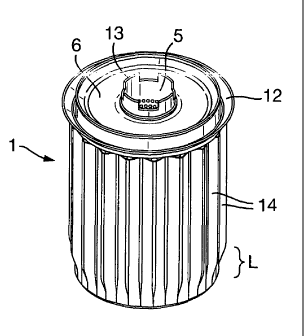
Figure 1 is a perspective view from above of the catalyst carrier of
the present invention;
Figure 2 is a perspective view of the catalyst carrier from below;
Figure 3 is a partial cross section viewed from the side;
Figure 4 is a simplified diagram of the catalyst carrier of the present
invention;
Figure 5 is a schematic illustration of a carrier of the present
invention from below when located within a tube:
9
CA 02771701 2012-02-21
WO 2011/048361 PCT/GB2010/001931
Figure 6 is a schematic cross section of three catalyst carriers
located within a tube; and
Figure 7 is an enlarged cross-section of Section A of Figure 6.
A catalyst carrier I of the present invention is illustrated in Figures 1 to
3. The carrier
comprises an annular container 2 which has perforated walls 3, 4. The inner
perforated
wall 3 defines a tube 5. A top surface 6 is closes the annular container at
the top. It is
located at a point towards the top of the walls 3, 4 of the annular container
2 such that a
lip 6 is formed. A bottom surface 7 closes the bottom of the annular container
2 and a
surface 8 closes the bottom of tube 5. The surface 8 is located in a lower
plane that that
of the bottom surface 7. Spacer means in the form of a plurality of
depressions 9 are
located present on the bottom surface 7 of the annular container 2. Drain
holes 10, 11 are
located on the bottom surface 7 and the surface 8.
A seal 12 extends from the upper surface 6 and an upstanding collar 13 is
provided
coaxial with the tube 5.
A corrugated upstanding skirt 14 surrounds the container 2. The corrugations
are
flattened in the region L towards the base of the carrier 1.
A catalyst carrier 1 of the present invention located in a reactor tube 15.
The flow of gas
is illustrated schematically in Figure 4 by the arrows.
When a plurality of catalyst carriers of the present invention are located
within a reactor
tube 15 they interlock as illustrated in Figures 6 and 7. The effect on the
flow path is
illustrated in the enlarged section shown in Figure 7.
The principle of the present invention will now be described by way of
illustration using
a simplified comparison.
CA 02771701 2012-02-21
WO 2011/048361 PCT/GB2010/001931
Comparing a tubular reactor with and without the present invention for the
same amount
of catalyst and overall tube length, the conventional reactor may need 12
tubes of 25 mm
internal diameter to hold the same amount of catalyst as a single 100 mm
internal
diameter tube containing catalyst in catalyst carriers of the present
invention (after
allowing for the loss of volume for catalyst within the carriers).
Approximately the same amount of heat will be generated or required so the
larger tube
will have to transmit this heat at a higher rate per unit of tube surface
area.
The 12 tubes of 25 mm internal diameter have a surface area three times the
surface area
of a single tube of 100 mm internal diameter. The high heat transfer rate
induced in the
micro channel zone at the tube wall compensates for this reduced area.
It will be understood that whilst the catalyst carrier has been described with
particular
reference to a use in a tube of circular cross-section the tube may be of non-
circular
cross-section for example, it may be a plate reactor. Where the tube is of non-
circular
cross-section, the carrier will be of the appropriate shape. In this
arrangement, the
annulus will not be a circular ring and this term should be constructed
accordingly.
11