Note: Descriptions are shown in the official language in which they were submitted.
CA 02771880 2012-02-22
DESCRIPTION
AIRBAG DEVICE
Technical Field
[0001] The present invention relates to an airbag device that is inflated and
deployed to
protect an occupant in the event of, for example, a vehicle collision.
Background Art
[0002] An airbag device for a passenger seat is disposed in an instrument
panel in a
normal state. In the event of a vehicle collision or the like, an airbag is
inflated and
deployed by tearing a lid provided in the instrument panel, to thereby protect
an occupant.
[0003] In the above-mentioned airbag device, an airbag is surrounded by a
plate
formed of a resin, metal or the like such that the airbag is inflated and
deployed in the
direction of tearing the lid in the instrument panel. Accordingly, airbag
devices tend to
be larger in weight.
[0004] Therefore, Patent Document 1 discloses an airbag module in which a
chute
assembly that secures an inflator device is formed of a fabric or the like,
the chute
assembly is secured to a square-frame-shaped collar formed of metal or the
like, and the
collar is attached to a vehicle.
Prior Art Document
Patent Document
[0005] Patent Document 1: Japanese Patent Application No. 2008-544920
Summary of the Invention
Problem to be Solved by the Invention
CA 02771880 2012-02-22
2
[0006] Unfortunately, in the airbag module disclosed in Patent Document 1, the
chute
assembly is attached to a vehicle through a square-frame-shaped color formed
of metal or
the like, and thus a weight reduction effect is insufficient.
[0007] Therefore, an object of the present invention is to reduce a weight of
a
configuration for suppressing an airbag from extending in a radial direction
as much as
possible.
Means to Solve the Problem
[0008] In order to solve the above-mentioned problem, a first aspect relates
to an
airbag device installed into an airbag-installation panel including a lid
portion configured
to be torn and a lid-side peripheral wall portion provided to stand on an
outer periphery of
the lid portion, which includes: an inflator disposed inside the lid portion
and configured
to generate gas; an airbag folded so as to be disposed between the lid portion
and the
inflator and configured to be inflated and deployed in a bag shape by the gas
introduced
from the inflator; and an outer bag formed of a sheet-like member to be sewn
into a
three-dimensional shape including an outer-bag-side bottom and an outer-bag-
side
peripheral wall portion provided on an outer periphery of the outer-bag-side
bottom, the
outer-bag-side bottom being secured to the inflator, the outer-bag-side
peripheral wall
portion surrounding the folded airbag and being disposed so as to be
sandwiched between
the airbag being inflated and deployed and the lid-side peripheral wall
portion.
[0009] According to a second aspect, in the airbag device of the first aspect,
an
extending portion is disposed at a distal end of the outer-bag-side peripheral
wall portion,
the extending portion being configured to be sandwiched between the airbag
being
inflated and deployed and an exterior surface of the airbag-installation panel
located on
the outer periphery side of the lid portion.
[0010] According to a third aspect, the airbag device of the first or second
aspect
CA 02771880 2012-02-22
3
further includes an inflator securing member including a reaction plate to
which the
inflator is secured and a securing bracket configured to be secured to a
vehicle-body-side
member, wherein the inflator is secured to a fixed location inside of the lid
portion upon
securing of the securing bracket to the vehicle-body-side member.
[0011] According to a fourth aspect, the airbag device of any one of the first
to third
aspects further includes a belt portion connected to the inflator and the lid-
side peripheral
wall portion and holding the inflator at a fixed location inside of the lid
portion.
[0012] According to a fifth aspect, in the airbag device of the fourth aspect,
one end of
the belt portion is connected to the inflator, and the other end of the belt
portion is caused
to pass through a mounting hole formed in the lid-side peripheral wall portion
to be
connected to the outer-bag-side peripheral wall portion.
[0013] According to a sixth aspect, in the airbag device of the fourth aspect,
a middle
portion of the belt portion in a longitudinal direction is caused to pass
through a mounting
hole formed in the lid-side peripheral wall portion, and both ends of the belt
portion are
connected to the inflator.
[0014] According to a seventh aspect, in the airbag device of the fourth
aspect, one end
of the belt portion is connected to the inflator, and the other end of the
belt portion is
interlocked with and secured to the lid-side peripheral wall portion through a
hook
portion.
Effects of the Invention
[0015] According to the airbag device of the first aspect, when the airbag is
inflated
and deployed, the outer-bag-side peripheral wall portion is sandwiched between
the
airbag that tries to be inflated and deployed and the lid-side peripheral wall
portion.
Accordingly, the state in which the outer-bag-side peripheral wall portion
surrounds the
airbag between the lid-side peripheral wall portion and the inflator is kept.
This
CA 02771880 2012-02-22
4
suppresses the airbag from spreading in a radial direction between the lid-
side peripheral
wall portion and the inflator. Further, the configuration for suppressing the
airbag from
spreading in the radial direction can be achieved by the outer bag formed
mainly of a
sheet-like member that is sewn into a three-dimensional shape, which reduces a
weight as
much as possible.
[0016] According to the second aspect, when the airbag is inflated and
deployed, the
extending portion provided at the distal end of the outer-bag-side peripheral
wall portion
is sandwiched between the airbag being inflated and deployed and a peripheral
portion
outside an opening of the airbag-installation panel after the lid portion is
torn, which
makes it difficult for the outer-bag-side peripheral wall portion to come off
the part
between the airbag being inflated and deployed and the lid-side peripheral
wall portion.
This suppresses the airbag from spreading in a radial direction between the
lid-side
peripheral wall portion and the inflator more reliably.
[0017] According to the third aspect, the inflator can be secured at a fixed
location
inside of the lid portion by a securing bracket, which simplifies or omits the
configuration
of securing the inflator and the airbag-installation panel to each other.
[0018] According to the fourth aspect, the inflator is held at a fixed
location inside of
the lid portion by the belt portion, which reduces a weight of the
configuration of securing
the inflator.
[0019] According to the fifth aspect, the other end of the belt portion passes
through
the mounting hole formed in the lid-side peripheral wall portion and then is
connected to
the outer-bag-side peripheral wall portion, which makes it difficult for the
outer-bag-side
peripheral wall portion to come off the part between the airbag being inflated
and
deployed and the lid-side peripheral wall portion. This suppresses the airbag
from
spreading in the radial direction between the lid-side peripheral wall portion
and the
CA 02771880 2012-02-22
inflator more reliably.
[0020] According to the sixth aspect, it is only required to connect the both
ends of the
belt portion to the inflator, which simplifies the connection structure
thereof.
[0021] According to the seventh aspect, the other end of the belt portion can
be easily
5 interlocked with and secured to the lid-side peripheral wall portion through
the hook
portion.
Brief Description of Drawings
[0022] FIG. 1 is a cross-sectional view showing an airbag device according to
a first
embodiment.
FIG. 2 is an exploded cross-sectional view showing the airbag device.
FIG. 3 is a perspective view showing an outer bag.
FIG. 4 is an explanatory view showing an outer bag manufacturing process.
FIG. 5 is an explanatory view showing the outer bag manufacturing process.
FIG. 6 is an explanatory view showing the outer bag manufacturing process.
FIG. 7 is an explanatory view showing the outer bag manufacturing process.
FIG. 8 is an explanatory view showing the outer bag manufacturing process.
FIG. 9 is an explanatory view showing the outer bag manufacturing process.
FIG. 10 is an explanatory view showing an operation of deploying the airbag
device.
FIG. 11 is an explanatory view showing the operation of deploying the airbag
device.
FIG. 12 is an explanatory view showing the operation of deploying the airbag
device.
FIG. 13 is an explanatory view showing an operation of deploying an airbag
CA 02771880 2012-02-22
6
device according to a modification of the first embodiment.
FIG. 14 is an explanatory view showing the operation of deploying the airbag
device according to the modification of the first embodiment.
FIG. 15 is an explanatory view showing the operation of deploying the airbag
device according to the modification of the first embodiment.
FIG. 16 is a cross-sectional view showing an airbag device according to a
second embodiment.
FIG. 17 is an exploded cross-sectional view showing the airbag device.
FIG. 18 is a perspective view showing an outer bag.
FIG. 19 is an explanatory view showing an outer bag manufacturing process.
FIG. 20 is an explanatory view showing the outer bag manufacturing process.
FIG. 21 is an explanatory view showing the outer bag manufacturing process.
FIG. 22 is an explanatory view showing the outer bag manufacturing process.
FIG. 23 is an explanatory view showing the outer bag manufacturing process.
FIG. 24 is an explanatory view showing the outer bag manufacturing process.
FIG. 25 is an explanatory view showing the outer bag manufacturing process.
FIG. 26 is an explanatory view showing the outer bag manufacturing process.
FIG. 27 is an explanatory view showing the outer bag manufacturing process.
FIG. 28 is an explanatory view showing the outer bag manufacturing process.
FIG. 29 is an explanatory view showing the outer bag manufacturing process.
FIG. 30 is an explanatory view showing the outer bag manufacturing process.
FIG. 31 is an explanatory view showing the outer bag manufacturing process.
FIG. 32 is an explanatory view showing an operation of deploying the airbag
device.
FIG. 33 is an explanatory view showing the operation of deploying the airbag
CA 02771880 2012-02-22
7
device.
FIG. 34 is an explanatory view showing the operation of deploying the airbag
device.
FIG. 35 is an explanatory view showing an operation of deploying an airbag
device according to a modification of the second embodiment.
FIG. 36 is an explanatory view showing the operation of deploying the airbag
device according to the modification of the second embodiment.
FIG. 37 is an explanatory view showing the operation of deploying the airbag
device according to another modification of the second embodiment.
FIG. 38 is an explanatory view showing an operation of deploying an airbag
device according to another modification of the second embodiment.
FIG. 39 is an explanatory view showing the operation of deploying the airbag
device according to the another modification of the second embodiment.
FIG. 40 is an explanatory view showing the operation of deploying the airbag
device according to the another modification of the second embodiment.
Embodiments for Carrying Out the Invention
[0023] {First Embodiment}
Hereinafter, an airbag device according to a first embodiment is described.
FIG. 1 is a cross-sectional view showing an entire configuration of an airbag
device 20
according to the present embodiment, and FIG. 2 is an exploded cross-sectional
view
showing the airbag device 20. FIG. 1 and FIG. 2 each show a cross section in a
surface
along a front and rear direction of a vehicle.
[0024] The airbag device 20 is installed into an instrument panel 10 located
in front of
a passenger seat of a vehicle, which is configured as a device that is
inflated and deployed
CA 02771880 2012-02-22
8
toward the front of a passenger-seat occupant in the event of, for example, a
vehicle
collision, to thereby brace the passenger-seat occupant and absorb an impact.
[0025] That is, the instrument panel 10 is disposed as an airbag-installation
panel in the
front of the passenger seat of the vehicle. Formed in the instrument panel 10
is a lid
portion 12 that can be torn. Here, the instrument panel 10 is formed of a
resin. A
groove-like tear line 13 is formed on the inner peripheral surface of the
instrument panel
so as to surround an approximately square-shaped region thereof from three
sides, and
accordingly the area surrounded by the tear line 13 corresponds to the lid
portion 12.
The airbag device 20 is installed inside the lid portion 12. When the airbag
device 20 is
10 activated, the instrument panel 10 is torn along the tear line 13, and the
lid portion 12 is
torn, to thereby form an opening. A lid-side peripheral wall portion 14 that
is provided
to stand on an outer periphery of the lid portion 12 is formed on the inner
surface of the
instrument panel 10. The lid-side peripheral wall portion 14 is positioned on
the side
closer to the outer periphery than the tear line 13 and surrounds the lid
portion 12 over the
entire outer periphery thereof. Note that the location at which the tear line
13 is formed
is not limited to the above-mentioned example, and is merely required to be
formed at the
location at which the opening for airbag deployment can be formed when the
airbag
device 20 operates.
[0026] A vehicle-body-side member 18 being a member secured to a vehicle body
is
disposed inside the instrument panel 10. Here, a member (member referred to as
reinforcement) that is secured to the body and is disposed along the vehicle
width
direction inside of the instrument panel 10 is assumed as the vehicle-body-
side member
18. The instrument panel 10 is secured to a vehicle body by a mounting
structure such
as a well-known structure, and the vehicle-body-side member 18 is secured to
the vehicle
body as well, whereby the instrument panel 10 and the vehicle-body-side-member
18 are
CA 02771880 2012-02-22
9
maintained in the fixed positional relationship.
[0027] The airbag device 20 is installed into the instrument panel 10 as
described
above. Note that the installation of the airbag device 20 into the instrument
panel 10
includes a case where the airbag device 20 is disposed at the location at
which the airbag
device 20 can be inflated and deployed from the instrument panel 10, and the
airbag
device 20 is not necessarily required to be secured to the instrument panel 10
physically
and mechanically.
[0028] The airbag device 20 includes an inflator 22, an airbag 30 and an outer
bag 50.
[0029] The inflator 22 includes an ignition device, a gas generator and the
like and is
disposed inside the lid portion 12. The inflator 22 is configured to ignite
and burn the
gas generator by the ignition device in response to, for example, an ignition
order signal
from an impact detecting part or the like placed in the vehicle itself, to
thereby generate
gas.
[0030] The airbag 30 is formed of a fabric or the like into a bag shape that
has a gas
inlet. The inflator 22 is mounted to the airbag 30 at the location and in the
position
where gas can be introduced into the airbag 30 through the gas inlet. In a
normal state,
the airbag 30 is folded to be disposed between the lid portion 12 and the
inflator 22. The
airbag 30 is configured to, when being inflated and deployed in the event of,
for example,
a vehicle collision, be inflated so as to project outside the instrument panel
10 by tearing
the lid portion 12, and then be inflated and deployed in a bag shape toward
the
passenger-seat occupant side being the room interior side, by the gas
introduced from the
inflator 22 through the gas inlet.
[0031] FIG. 3 is a perspective view showing the outer bag 50. As shown in FIG.
1 to
FIG. 3, the outer bag 50 is configured by sewing a flexible sheet-like member
that can be
folded as well as sewn, such as a fabric or a resin sheet, in a three-
dimensional shape, and
CA 02771880 2012-02-22
includes an outer-bag-side bottom 52 and an outer-bag-side peripheral wall
portion 54.
[0032] The outer-bag-side bottom 52 is the part secured to the inflator 22. In
this case,
the outer-bag-side bottom 52 is formed into an approximately square shape, and
an
opening 52h having a shape and size corresponding to an inlet of the airbag 30
is formed
5 approximately in the center portion thereof. Further, a plurality of outer
bag securing
holes 52a are formed on the outer periphery of the opening 52h in the outer-
bag-side
bottom 52. The outer-bag-side bottom 52 is secured to the inflator 22 by means
of the
outer bag securing holes 52a as described below. Securing holes are formed at
locations
corresponding to the plurality of outer bag securing holes 52a in the airbag
30 and an
10 annular projection 22F provided around the inflator 22.
[0033] The outer-bag-side peripheral wall portion 54 is provided on the outer
periphery
of the outer-bag-side bottom 52, which is provided so as to surround a
principal surface
side of the outer-bag-side bottom 52 in an approximately square annular shape.
More
specifically, the outer-bag-side peripheral wall portion 54 includes first
side wall portions
54a and 54b that are extended from a pair of opposing short sides of the outer-
bag-side
bottom 52, and second side wall portions 54c and 54d that are extended from a
pair of
opposing long sides of the outer-bag-side bottom 52. The side edges of the
first side
wall portions 54a and 54b are sewn to the side edges of the second side wall
portions 54c
and 54d between adjacent ones, thereby forming the outer-bag-side peripheral
wall
portion 54 having an approximately square tube shape. That is, it can be
considered that
the outer bag 50 has an approximately housing shape with one side being open
by the
outer-bag-side bottom 52 and the outer-bag-side peripheral wall portion 54.
Needless to
say, the shape of the outer bag 50 may be a shape obtained by closing one end
of an
elliptical tube shape, a tube shape or a polygonal tube shape correspondingly
to the shape
of the inner peripheral surface of the lid-side peripheral wall portion 14.
CA 02771880 2012-02-22
11
[0034] A projecting dimension of the outer-bag-side peripheral wall portion 54
from
the outer-bag-side bottom 52 is set to a dimension to such an extent that at
least part of
the outer-bag-side peripheral wall portion 54 is sandwiched between the airbag
30 being
inflated and deployed and the lid-side peripheral wall portion 14 when the
airbag 30 is
inflated and deployed (in other words, to such an extent that it is disposed
to be
superimposed on the inner side of the lid-side peripheral wall portion 14 when
being
inflated and deployed) (see FIG. 12). For example, when the dimension between
the
outer periphery of the inflator 22 and the outer periphery at the distal end
of the lid-side
peripheral wall portion 14 when the airbag 30 is inflated and deployed is
represented as M,
it is preferable that a projecting dimension L of the outer-bag-side
peripheral wall portion
54 from the outer-bag-side bottom 52 be a dimension obtained by adding an
additional
dimension a to the dimension M. The additional dimension a is a dimension
enough to
keep the state in which at least part of the outer-bag-side peripheral wall
portion 54 is
sandwiched between the airbag 30 being inflated and deployed and the lid-side
peripheral
wall portion 14 in consideration of, for example, outward swelling of the
outer-bag-side
bottom 52 due to the airbag 30 being inflated and deployed. Such an additional
dimension a can be set experimentally and empirically by taking the
performance or the
like of the airbag 30 or inflator 22 into consideration. In this case, the
projecting
dimension of the outer-bag-side peripheral wall portion 54 from the outer-bag-
side
bottom 52 is set to be approximately identical to the thickness dimension of
the folded
airbag 30. The outer-bag-side peripheral wall portion 54 surrounds four sides
of the
folded airbag 30 in a normal state.
[0035] First extending portions 55a and 55b are provided at the distal ends of
the first
side wall portions 54a and 54b, respectively, and second extending portions
55c and 55d
are provided at the distal ends of the second side wall portions 54c and 54d,
respectively.
CA 02771880 2012-02-22
12
The first extending portion 55a and the second extending portions 55c and 55d
are formed
in an approximately trapezoidal shape in which those become gradually narrower
toward
the distal ends, and are configured to cover the upper portion of the folded
airbag 30 in
such a manner that those hardly overlap each other. The first extending
portion 55b is
formed into an approximately square shape, and an extending portion for
enclosure 55f is
extended at the distal end thereof. The first extending portion 55b and the
extending
portion for enclosure 55f are connected to each other through a weakened part
55e that
can be torn upon the airbag 30 being inflated and deployed. Here, the weakened
part
55e is formed by partially cutting the part between the first extending
portion 55b and the
extending portion for enclosure 55f in a linear manner. An arc-shaped recess
55g is
formed at the distal end of the extending portion for enclosure 55f
correspondingly to the
outer peripheral shape of the inflator 22, and securing holes 55h are formed
at locations
that are located on the outer periphery of the arc-shaped recess 55g and
correspond to
parts of the outer bag securing holes 52a. The first extending portion 55b and
the
extending portion for enclosure 55f cover the upper portion of the folded
airbag 30 from
outer sides of the first extending portion 55a and the second extending
portions 55c and
55d. In this state, the weakened part 55e is set so as to be located at an
approximately
center of the upper portion of the folded airbag 30. The extending portion for
enclosure
55f wraps around the bottom side (inflator 22 side) after passing through the
side of the
folded airbag 30 from the upper portion thereof, and is secured to the
inflator 22.
[0036] The first extending portions 55a and 55b and the second extending
portions 55c
and 55d are configured so as to be sandwiched between the airbag 30 being
inflated and
deployed and the outer peripheral surface of the lid portion 12 of the
instrument panel 10
when the airbag 30 is inflated and deployed (see FIG. 12). That is, the first
extending
portions 55a and 55b and the second extending portions 55c and 55d are set to
dimensions
CA 02771880 2012-02-22
13
to such an extent that those extend beyond the lid-side peripheral wall
portion 14, pass
through the openings formed in the instrument panel 10, and extend outwardly.
[0037] In the present embodiment, the outer bag 50 is secured to the inflator
22 but is
not secured to the instrument panel 10 and the lid portion 12.
[0038] Description is given of an example of the method of manufacturing the
outer
bag 50.
[0039] First, as shown in FIG. 4, a sheet-like member formed of a fabric or
the like is
appropriately cut, to thereby form a sheet-like member having an approximately
cross
shape in which the first side wall portions 54a and 54b and the second side
wall portions
54c and 54d extend from four sides of the outer-bag-side bottom 52 having an
approximately square shape. The first extending portion 55a and the second
extending
portions 55c and 55d are extended at the distal ends of the first side wall
portion 54a and
the second side wall portions 54c and 54d, respectively, and the first
extending portion
55b and the extending portion for enclosure 55f are extended at the distal end
of the first
side wall portion 54b.
[0040] Then, the side edges of the first side wall portions 54a and 54b and
the second
side wall portions 54c and 54d are sewn together along seams 54L shown in FIG.
5.
Accordingly, as shown in FIG. 6 and FIG. 7, the outer bag 50 is three-
dimensionally sewn
into an approximately housing shape in which one side (upper side) is open.
Next, as
shown in FIG. 8 and FIG. 9, the outer bag 50 immediately after sewing is
turned inside
out, to thereby obtain the outer bag 50 that has an approximately housing
shape in which
one side (upper side) is open and seams are located inside. Then, the folded
airbag 30 is
housed and arranged in this outer bag 50, and in that housed state, the first
extending
portions 55a and 55b, the second extending portions 55c and 55d and the
extending
portion for enclosure 55f are tucked in an outer peripheral shape of the
folded airbag 30.
CA 02771880 2012-02-22
14
[0041] It suffices that in the above-mentioned outer bag 50, for example, a
superimposed structure of a plurality of sheets is appropriately employed
entirely or
partially in accordance with the necessity in strength or the like.
[0042] The mounting structure of the inflator 22, the airbag 30 and the outer
bag 50 is
described.
[0043] As shown in FIG. 1 and FIG. 2, the configuration for mounting the
inflator 22,
the airbag 30 and the outer bag 50 includes an inner ring member 40 and an
inflator
securing member 42.
[0044] The inner ring member 40 is formed of a metal plate or the like, which
is
formed as a ring-shaped member having approximately the same hole as the inlet
formed
in the airbag 30. The inner ring member 40 is a member also referred to as a
cushion
ring. In the inner ring member 40, a plurality of securing bolts 40B are
provided as
securing members in a projecting manner at the locations respectively
corresponding to
the plurality of outer bag securing holes 52a described above (or securing
holes of the
airbag 30).
[0045] The inflator securing member 42 includes a reaction plate 43 and a
securing
bracket 45.
[0046] The reaction plate 43 is formed of a metal plate or the like, which is
formed into
a plate shape capable of closing the inner opening of the lid-side peripheral
wall portion
14 at least partially, in this case, a plate shape smaller than the inner
opening of the
lid-side peripheral wall portion 14. A mounting hole 43h having approximately
the
same size and shape as those of the inlet formed in the airbag 30 is formed in
the reaction
plate 43. Further, around an outer periphery of the mounting hole 43h of the
reaction
plate 43, a plurality of mounting holes are formed at the respective locations
corresponding to the above-mentioned plurality of outer bag securing holes 52a
(or
CA 02771880 2012-02-22
securing holes of the airbag 30).
[0047] Then, the inner ring member 40 is disposed on the periphery of the
inlet in the
airbag 30, and the airbag 30 is folded. After that, the securing bolts 40B are
caused to
pass through the mounting holes formed in the airbag 30, the outer bag 50, the
reaction
5 plate 43 and the inflator 22 in this order, whereby securing nuts ON are
screwed and
fastened with the securing bolts 40B. As a result, the airbag 30, the outer
bag 50 and the
reaction plate 43 are mounted and secured in the state of being sandwiched
between the
inner ring member 40 and the annular projection 22F of the inflator 22.
[0048] Needless to say, the securing structure of the respective
configurations is not
10 limited to the example above. For example, an outer bag may be secured to a
reaction
plate or the like and may be secured indirectly to the inflator 22 through the
reaction plate
or the like. Alternatively, a reaction plate may be not provided.
[0049] The securing bracket 45 is a member formed of a metal plate or the
like, and
includes a plate-side securing part 45a secured to the reaction plate 43 and a
15 vehicle-body-side securing part 45b secured to the vehicle-body-side member
18. The
plate-side securing part 45a is disposed along a back surface of the reaction
plate 43, and
is secured to the reaction plate 43 by causing the securing bolts 43B provided
in the
reaction plate 43 in a projecting manner to pass through the part 45a and, for
example,
screwing and fastening the nuts 43N with the securing bolts 43B (see FIG. 2).
Meanwhile, the vehicle-body-side securing part 45b extends from the plate-side
securing
part 45a to the vehicle-body-side member 18 and is secured to the vehicle-body-
side
member 18. In this case, a vehicle-body-side securing bolt 18B provided in a
projecting
manner in the vehicle-body-side member 18 is caused to pass through the
vehicle-body-side securing part 45b, and a nut 18N is screwed and fastened
with the
vehicle-body-side securing bolt 18B, whereby the vehicle-body-side securing
part 45b is
CA 02771880 2012-02-22
16
secured to the vehicle-body-side member 18 (see FIG. 1).
[0050] Then, the securing bracket 45 is secured to the vehicle-body-side
member 18,
so that the inflator 22 is secured to a fixed location (that is, a location
spaced for
disposing the folded airbag 30 between the lid portion 12 and the inflator 22)
inside of the
lid portion 12 through the reaction plate 43.
[0051] Note that fixation of a fixing bracket to a reaction plate or a vehicle-
body-side
member is not limited to the example above, which may be, for example,
caulking or
welding, fitting structure, or a composite configuration of those. Further,
the securing
bracket may be configured to be secured indirectly to the inflator through the
reaction
plate or the like as described above, or may be configured to be secured
directly to the
inflator. Further, the securing bracket may be secured to any part on the
vehicle-body-side as long as it is not a mounting panel that entirely covers
the airbag
device 20 in a normal state.
[0052] FIG. 10 to FIG. 12 are explanatory views showing the operation of
deploying
the airbag device 20. Note that the explanatory views showing the deployment
operation are simplified for the sake of description.
[0053] First, in a normal state before the deploying operation, as shown in
FIG. 10, the
folded airbag 30 is disposed between the lid portion 12 and the inflator 22.
In this state,
the lid-side peripheral wall portion 14 surrounds the folded airbag 30 from
four sides
thereof. The first side wall portions 54a and 54b and the second side wall
portions 54c
and 54d of the outer bag 50 surround the folded airbag 30 from four sides
thereof, and the
first extending portions 55a and 55b and the second extending portions 55c and
55d cover
the upper portion of the folded airbag 30.
[0054] When the gas from the inflator 22 is introduced into the airbag 30 in
this state,
as shown in FIG. 11, the airbag 30 starts to be inflated in the space
surrounded by the lid
CA 02771880 2012-02-22
17
portion 12, the lid-side peripheral wall portion 14 and the inflator 22.
[0055] On this occasion, in the direction in which the airbag 30 mainly
projects
(direction from the inflator 22 toward the lid portion 12), the inflator 22 is
secured at the
location spaced from the lid portion 12 by a certain distance by the inflator
securing
member 42, whereby the force for inflating and deploying the airbag 30 in the
projecting
direction acts as the force for splitting the tear line 13 of the lid portion
12. Accordingly,
the lid portion 12 is torn, to thereby form an opening in the instrument panel
10.
[0056] On this occasion, the airbag 30 tries to be inflated and deployed also
in a radial
direction toward the surrounding of the mainly projecting direction (direction
from the
inflator 22 toward the lid portion 12) being the center. In this case, in the
part in which
the lid-side peripheral wall portion 14 is located, the airbag 30 that tries
to be inflated and
deployed is pressed against the inner surface of the lid-side peripheral wall
portion 14,
whereby the outer-bag-side peripheral wall portion 54 is held so as to be
sandwiched
between the airbag 30 and the lid-side peripheral wall portion 14. As a
result, the part of
the outer-bag-side peripheral wall portion 54, which is interposed between the
lid-side
peripheral wall portion 14 and the inflator 22, braces the portion of the
airbag 30 that tries
to be inflated and deployed in the vicinity of the inflator 22 over the entire
periphery.
This suppresses the airbag 30 from being inflated and deployed outwardly so as
to spread
between the lid-side peripheral wall portion 14 and the inflator 22 in the
radial direction.
[0057] Then, when the lid portion 12 is torn, as shown in FIG. 12, the airbag
30 is
inflated and deployed outwardly after passing through the opening of the
instrument panel
10. Further, the weakened part 55e of the outer bag 50 is also split by the
force for
inflating and deploying the airbag 30 before/after the rid portion 12 is torn
by the airbag
30. Then, when the airbag 30 is inflated and deployed outwardly after passing
through
the opening of the instrument panel 10, the first extending portions 55a and
55b and the
CA 02771880 2012-02-22
18
second extending portions 55c and 55d are pushed outwardly after passing
through the
opening of the instrument panel 10, and are held so as to be sandwiched
between the
periphery of the opening or the torn lid portion 12 of the instrument panel 10
and the
airbag 30 being inflated and deployed. Accordingly, in the state in which the
airbag 30
is inflated and deployed outside the instrument panel 10, the state in which
the
outer-bag-side peripheral wall portion 54 partially overlaps the lid-side
peripheral wall
portion 14 is maintained by at least one of the configuration in which the
outer-bag-side
peripheral wall portion 54 is sandwiched between the airbag 30 and the lid-
side peripheral
wall portion 14 and the configuration in which the first extending portions
55a and 55b
and the second extending portions 55c and 55d are sandwiched between the
periphery of
the opening of the instrument panel 10 and the airbag 30 being inflated and
deployed.
Accordingly, similarly to the above, the part of the outer-bag-side peripheral
wall portion
54, which is interposed between the lid-side peripheral wall portion 14 and
the inflator 22,
braces the part of the airbag 30 being inflated and deployed in the vicinity
of the inflator
22 over the entire periphery, which suppresses the airbag 30 from spreading in
the radial
direction between the lid-side peripheral wall portion 14 and the inflator 22.
[0058] Then, the airbag 30 is inflated and deployed between the instrument
panel 10
and the passenger-seat occupant to brace the passenger-seat occupant and
absorb an
impact.
[0059] According to the airbag device 20 configured as described above, when
the
airbag 30 is inflated and deployed, the outer-bag-side peripheral wall portion
54 is
sandwiched between the airbag 30 that tries to be inflated and the lid-side
peripheral wall
portion 14. This sandwiching and holding force keeps the state in which the
outer-bag-side peripheral wall portion 54 surrounds the airbag 30 between the
lid-side
peripheral wall portion 14 and the inflator 22. This suppresses the airbag 30
from
CA 02771880 2012-02-22
19
spreading in the radial direction between the lid-side peripheral wall portion
14 and the
inflator 22. At the stage in which the necessity of suppressing the airbag 30
from
spreading in the radial direction within the instrument panel 10 decreases,
such as after
the airbag 30 is sufficiently inflated and deployed outside the instrument
panel 10, the
outer-bag-side peripheral wall portion 54 may come off the inner surface side
of the
lid-side peripheral wall portion 14.
[0060] Moreover, the side edges of the first side wall portions 54a and 54b
and the
second side wall portions 54c and 54d are sewn together to form the outer-bag-
side
peripheral wall portion 54 into an approximately square tube shape, with the
result that
the force for inflating and deploying the airbag 30 in the radial direction is
also
experienced by the structure of surrounding the airbag 30 by the outer-bag-
side peripheral
wall portion 54. For this reason, the force for causing the outer-bag-side
peripheral wall
portion 54 to come off the part between the airbag 30 and the lid-side
peripheral wall
portion 14 is hard to act. Also from this point, the state in which the outer-
bag-side
peripheral wall portion 54 surrounds the airbag 30 between the lid-side
peripheral wall
portion 14 and the inflator 22 is maintained, which suppresses the airbag 30
from
spreading in the radial direction between the lid-side peripheral wall portion
14 and the
inflator 22 more reliably.
[0061] Further, the configuration for suppressing the airbag 30 from spreading
in the
radial direction as described above can be achieved mainly by the outer bag 50
that is
sewn more three-dimensionally than a sheet-like member. Accordingly, it is not
required to, for example, provide a standing wall or the like for suppressing
the airbag 30
from being inflated in the radial direction in the reaction plate 43, and the
standing wall
can be omitted or made smaller. This reduces the weight of the airbag device
20 as
much as possible.
CA 02771880 2012-02-22
[0062] Further, when the airbag 30 is inflated and deployed, the first
extending
portions 55a and 55b and the second extending portions 55c and 55d provided at
the distal
ends of the outer-bag-side peripheral wall portion 54 are sandwiched between
the airbag
being inflated and deployed and the outer periphery of the opening of the
instrument
5 panel 10. Accordingly, even after the airbag 30 is inflated and deployed
outwardly, the
outer-bag-side peripheral wall portion 54 becomes difficult to come off the
part between
the airbag 30 and the lid-side wall peripheral wall portion 14. This
suppresses the airbag
30 from spreading in the radial direction between the lid-side peripheral wall
portion 14
and the inflator 22 more reliably.
10 [0063] Needless to say, the first extending portions 55a and 55b and the
second
extending portions 55c and 55d are not necessarily required. Also in this
case, as shown
in FIG. 13 to FIG. 15, the outer-bag-side peripheral wall portion 54 is
sandwiched
between the airbag 30 being inflated and deployed and the lid-side peripheral
wall portion
14, and accordingly the state in which the outer-bag-side peripheral wall
portion 54
15 surrounds the airbag 30 between the lid-side peripheral wall portion 14 and
the inflator 22
is maintained by this sandwiching and holding force, which suppresses the
airbag 30 from
spreading in the radial direction between the lid-side peripheral wall portion
14 and the
inflator 22.
[0064] Further, the inflator 22 is secured to a fixed location inside of the
lid portion 12
20 by means of the securing bracket 45, and thus the structure of securing the
inflator 22 and
the instrument panel 10 can be simplified or omitted. For example, it suffices
that the
inflator 22, the airbag 30, the outer bag 50 and the like are secured to the
vehicle-body-side by means of the securing bracket 45 and the instrument panel
10 is
installed such that the airbag 30 part is disposed in the space surrounded by
the lid portion
25 12 and the lid-side peripheral wall portion 14, which makes the operation
of assembling
CA 02771880 2012-02-22
21
the airbag device 20 and the instrument panel 10 easier.
[0065] Needless to say, an inflator or reaction plate may be secured to an
instrument
panel. Also in this case, the securing structure therefor does not need to be
robust
enough to withstand the force when an airbag is inflated and deployed, which
may be a
simplified securing structure.
[0066] {Second Embodiment}
An airbag device according to a second embodiment is described. FIG. 16 is a
cross-sectional view showing an entire configuration of an airbag device 120
according to
the present embodiment, and FIG. 17 is an exploded cross-sectional view
showing the
airbag device 120. FIG. 16 and FIG. 17 each show a cross section in a surface
along a
front and rear direction of a vehicle. In the description of the present
embodiment,
identical components to those described in the first embodiment are denoted by
identical
symbols and description thereof is omitted, and differences from the first
embodiment are
mainly described.
[0067] First, the airbag device 120 is installed into an instrument panel 110
as follows.
That is, the instrument panel 110 is disposed in front of a passenger seat of
a vehicle,
similarly to the instrument panel 10. The instrument panel 110 includes an
instrument
panel main body 11OA secured to the vehicle body and a lid panel portion 1 IOB
mounted
to the instrument panel main body 11 OA. An opening (in this case,
approximately
square-shaped opening) is formed in the instrument panel main body 11OA, and
the lid
panel portion 1 l OB is interlocked with and secured to the opening. The lid
panel portion
11OB is secured by, for example, engaging an engaging portion 110Ba formed in
the lid
panel portion 1 l OB with an engagement part (not shown) formed in the
instrument panel
main body l l OA.
[0068] The lid panel portion 11OB is formed of a resin or the like, and is
used as an
CA 02771880 2012-02-22
22
airbag-installation panel in which the airbag device 120 is installed. A lid
portion 112
similar to the lid portion 12 is formed in the lid panel portion 1 l OB.
[0069] A lid-side peripheral wall portion 114 that is provided to stand on an
outer
periphery of the lid portion 112 is formed on the inner surface of the lid
panel portion
110B. The lid-side peripheral wall portion 114 surrounds the lid portion 112
over the
entire outer periphery similarly to the lid-side peripheral wall portion 14.
However,
differently from the lid-side peripheral wall portion 14, the lid-side
peripheral wall
portion 114 is inclined with respect to the principal surface of the lid panel
portion 1 IOB
and extends so as to be directed approximately vertically downward in the
state in which
the lid panel portion 1 IOB is mounted to the instrument panel main body 11OA.
In this
state, a lower end of a side wall portion 114A (left in FIG. 16) of the lid-
side peripheral
wall portion 114 on one side located in the front of the car is located above
a lower end of
a side wall portion 114B (right in FIG. 16) thereof on the other side located
in the back of
the vehicle. Further, mounting holes 114Ah and 114Bh for connecting a belt
portion
170 described below are formed in the side wall portions 114A and 114B.
[0070] The airbag device 120 includes the inflator 22, the airbag 30 and the
outer bag
50, and further includes belt portions 170 and 172.
[0071] FIG. 18 is a perspective view showing the outer bag 50 and the belt
portions
170 and 172 in the course of assembly. As shown in FIG. 16 to FIG. 18, the
belt
portions 170 and 172 are members that are connected to the inflator 22 and the
lid-side
peripheral wall portion 114 and hold the inflator 22 at a fixed location
inside of the lid
portion 112. In this case, description is given of an example in which one
ends of the
belt portions 170 and 172 are connected to the inflator 22, and the other ends
of the belt
portions 170 and 172 are caused to pass through the mounting holes 114Ah and
114Bh
formed in the lid-side peripheral wall portion 114 and are connected to the
outer-bag-side
CA 02771880 2012-02-22
23
peripheral wall portion 54.
[0072] That is, a pair of belt portions 170 are connected to the second side
wall portion
54c on one side of the outer bag 50, and a pair of belt portions 172 are
connected to the
second side wall portion 54d on the other side thereof.
[0073] The pair of belt portions 170 are configured to be integrated together
at a
proximal end, separated from each other at the middle portion in the
longitudinal
direction through a hole portion (having a shape becoming gradually narrower
from the
proximal end toward the distal end in this case), and separated from each
other at the
distal end by, for example, cutting. The distal ends of the pair of belt
portions 170 have
an arc-shaped recessed edge corresponding to the outer peripheral shape of the
inflator 22,
and the mounting hole is formed at the location that is located on the outer
periphery of
the recessed edge and corresponds to the mounting hole formed around the air
inlet of the
airbag 30. The proximal end of the pair of belt portions 170 is connected to
the outer
peripheral surface of the second side wall portion 54c on one side, and
extends upwardly
from the second side wall portion 54c in the state before it is attached to
the lid-side
peripheral wall portion 114 (see FIG. 18).
[0074] The pair of belt portions 172 have approximately the identical
configuration to
that of the pair of belt portions 170 except for that the length dimension
thereof is
different from that of the pair of belt portions 170. The proximal end of the
pair of belt
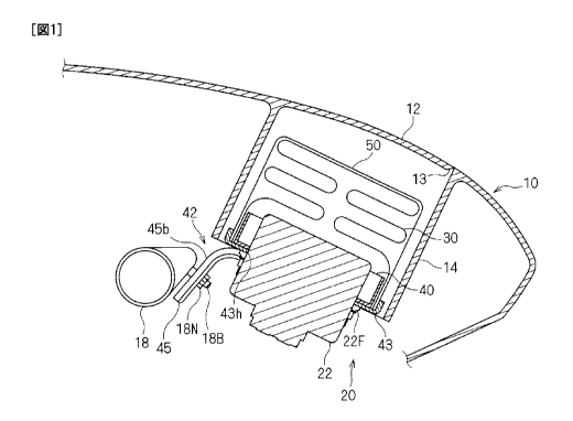
portions 172 is connected to the outer peripheral surface of the second side
wall portion
54d on the other side, and extends upwardly from the second side wall portion
54d in the
state before it is attached to the lid-side peripheral wall portion 114 (see
FIG. 18).
[0075] Description is now given of an example of a manufacturing method for
the
outer bag 50 and the pairs of belt portions 170 and 172.
[0076] First, a sheet-like member such as a fabric is appropriately cut, to
thereby
CA 02771880 2012-02-22
24
manufacture sheet-like members shown in FIG. 19 to FIG. 22.
[0077] FIG. 19 shows a sheet-like member similar to the sheet-like member
shown in
FIG. 14 described in the first embodiment. FIG. 20 shows a sheet-like member
having
an approximately cross shape that is superimposed on the member shown in FIG.
19. In
this manufacturing example, description is given of an example in which the
outer bag 50
has a double configuration with the sheet-like member shown in FIG. 20, but
the
sheet-like member is not necessarily required. In the description other than
the
description on the manufacturing method, the sheet-like member shown in FIG.
20 is
omitted. FIG. 21 shows a sheet-like member forming the pair of belt portions
170, and
FIG. 22 shows a sheet-like member forming the pair of belt portions 172, and
two sheets
are prepared respectively.
[0078] The two sheet-like members shown in FIG. 21 are sewn together in a
superimposed manner, to thereby manufacture the pair of belt portions 170 as
shown in
FIG. 23. The two sheet-like members shown in FIG. 22 are sewn together in a
superimposed manner, to thereby manufacture the pair of belt portions 172 as
shown in
FIG. 24.
[0079] As shown in FIG. 25, the sheet-like member shown in FIG. 19 and the
sheet-like member shown in FIG. 20 are superimposed on each other.
[0080] Then, as shown in FIG. 26, the proximal ends of the pair of belt
portions 170
and 172 are connected to the parts of the superimposed sheet-like members
shown in FIG.
that are correspond to the second side wall portions 54c and 54d by sewing or
the like.
[0081] Then, as in the first embodiment, the side edges of the first side wall
portions
54a and 54b and the second side wall portions 54c and 54d are sewn together
along the
seams 54L shown in FIG. 27. Accordingly, the outer bag 50 is obtained, which
is
25 three-dimensionally sewn into an approximately housing shape with one side
(upper side)
CA 02771880 2012-02-22
being open.
[0082] Then, the outer bag 50 immediately after sewing is turned inside out,
to thereby
obtain, as shown in FIG. 30 and FIG. 31, the outer bag 50 that has an
approximately
housing shape with one side (upper side) being open and seams located inside,
in which
5 the pairs of belt portions 170 and 172 are sewn to the outer surfaces of the
second side
wall portions 54c and 54d. As in the first embodiment, the folded airbag 30 is
housed in
the outer bag 50 so as to be enveloped.
[0083] The structure for mounting the above-mentioned inflator 22, airbag 30,
outer
bag 50 and pairs of belt portions 170 and 172 is described.
10 [0084] First, as in the first embodiment, the inflator 22, the airbag 30
and the outer bag
50 are secured to each other with the inner ring member 40 and an inflator
securing
member 142.
[0085] The inflator securing member 142 includes a reaction plate 143 similar
to the
reaction plate 43.
15 [0086] Then, as in the first embodiment, the inner ring member 40 is
disposed on the
periphery of the inlet in the folded airbag 30, and the securing bolts 40B
thereof are
caused to pass through the mounting holes formed in the airbag 30, the outer
bag 50, the
reaction plate 143 and the inflator 22 in this order, whereby the securing
nuts 40N are
screwed and fastened with the securing bolts 40B. As a result, the airbag 30,
the outer
20 bag 50 and the reaction plate 143 are mounted and secured in the state of
being
sandwiched between the inner ring member 40 and the annular projection 22F of
the
inflator 22.
[0087] With reference to FIG. 16 and FIG. 17, a back-surface-side auxiliary
bracket
144 is extended on the back surface side of the reaction plate 143. The
25 back-surface-side auxiliary bracket 144 is mounted and secured to, for
example, the
CA 02771880 2012-02-22
26
vehicle-body-side member 18 by screwing or the like. With reference to FIG.
17, side
auxiliary brackets 145 are extended on the sides of the reaction plate 143.
The side
auxiliary brackets 145 are mounted and secured to, for example, the lid-side
peripheral
wall portion 114 by screwing, fitting structure or the like.
[0088] Needless to say, those back-surface-side auxiliary bracket 144 and side
auxiliary bracket 145 may be omitted, and also in a case where those are not
omitted,
robust securing is not required enough to withstand the force when the airbag
is inflated
and deployed, which may be a simple securing structure.
[0089] Needless to say, the securing structure of those components is not
limited to the
example described above. For example, an outer bag may be secured to a
reaction plate
or the like and secured indirectly to the inflator 22 through the reaction
plate or the like.
[0090] Description is given of the configuration for mounting an integrated
structure of
the inflator 22, the airbag 30 and the outer bag 50 to the lid panel portion 1
l OB.
[0091] First, the folded airbag 30 and the outer bag 50 that envelopes this
are pushed
inside the lid-side peripheral wall portion 114 while causing the pair of belt
portions 170
and the pair of belt portions 172 to pass through the mounting holes 114Ah and
114Bh of
the side wall portions 114A and 114B of the lid-side peripheral wall portion
114,
respectively, from the inside.
[0092] After that, the pair of belt portions 170 and the pair of belt portions
172 are
folded back toward the inflator 22 from the outer surface of the lid-side
peripheral wall
portion 114 along the back surface side of the reaction plate 143. Then, the
securing
bolts 40B of the inner ring member 40, which project toward the back surface
side of the
annular projection 22F of the inflator 22, are caused to pass through the
mounting holes
on the distal end side of the pair of belt portions 170 and the pair of belt
portions 172.
Then, the securing nuts 40N are screwed and fastened with the securing bolts
40B.
CA 02771880 2012-02-22
27
Before entering this state, the securing nuts 40N may be loosely fastened with
the
securing bolts 40B such that the securing nuts 40 are detached as required.
This allows
the inflator 22 to be held at a location with a predetermined spacing from the
lid portion
112. From another viewpoint, the pair of belts 170 and 172 serve to suppress
the airbag
30 from going up toward the direction of becoming apart from the inflator 22
when the
airbag 30 is inflated and deployed.
[0093] Then, as described above, the lid panel portion 110B to which the
inflator 22,
the airbag 30 and the outer bag 50 are mounted is fitted with the opening of
the
instrument panel main body 110A from the outside thereof, whereby the airbag
device
120 is installed into the instrument panel 110. On this occasion, the robust
securing
structure of the airbag device 120 and the vehicle-body-side member 18 is not
required,
which enables to install the airbag device 120 relatively with ease.
[0094] FIG. 32 to FIG. 34 are explanatory views showing an operation of
deploying
the airbag device 20. Those figures are simplified such that, for example, the
side wall
portion 114A and the side wall portion 114B of the lid-side peripheral wall
portion 114
are shown to be approximately flush with each other and the first extending
portions 55a
and 55b and the second extending portions 55c and 55d of the outer bag 50 are
omitted,
for the sake of description.
[0095] First, as shown in FIG. 32, the folded airbag 30 is disposed between
the lid
portion 112 and the inflator 22 in the normal state before the deploying
operation. In
this state, the lid-side peripheral wall portion 114 surrounds the upper end
portion of the
folded airbag 30 from surrounding four sides. The first side wall portions 54a
and 54b
and the second side wall portions 54c and 54d of the outer bag 50 surround the
folded
airbag 30 from the surrounding four sides.
[0096] In this state, the gas from the inflator 22 is introduced into the
airbag 30, and
CA 02771880 2012-02-22
28
then, as shown in FIG. 33, the airbag 30 starts to be inflated in the space
surrounded by
the lie portion 112, the lid-side peripheral wall portion 114 and the inflator
22.
[0097] On this occasion, the inflator 22 is held at a location with a
predetermined
spacing from the lid portion 112 by the belt portions 170 and 172 in the
direction in which
the airbag 30 mainly projects (direction from the inflator 22 toward the lid
portion 112),
and thus the force for inflating and deploying the airbag 30 in the mainly
projecting
direction acts as the force for tearing the lid portion 112.
[0098] On this occasion, as in the first embodiment, the airbag 30 tries to be
inflated
and deployed also in the radial direction around the mainly projecting
direction (direction
from the inflator 22 toward the lid portion 112) being the center. Then, as in
the first
embodiment, in the part in which the lid-side peripheral wall portion 114 is
present, the
airbag 30 that tries to be inflated and deployed is pressed against the inner
surface of the
lid-side peripheral wall portion 114, and accordingly the outer-bag-side
peripheral wall
portion 54 is held so as to be sandwiched between the airbag 30 and the lid-
side
peripheral wall portion 114. The part of the outer-bag-side peripheral wall
portion 54
that is interposed between the lid-side peripheral wall portion 114 and the
inflator 22
braces the part of the airbag 30 that tries to be inflated and deployed, which
is in the
vicinity of the inflator 22. This enables to suppress the airbag 30 from being
inflated
and deployed outwardly in a manner of spreading in the radial direction
between the
lid-side peripheral wall portion 114 and the inflator 22.
[0099] Then, the lid portion 112 is torn, and accordingly, the airbag 30 is
inflated and
deployed outwardly after passing through the opening of the instrument panel
110 as
shown in FIG. 34. Also in this state, with the configuration in which the
outer-bag-side
peripheral wall portion 54 is sandwiched between the airbag 30 and the lid-
side peripheral
wall portion 114, the state in which the outer-bag-side peripheral wall
portion 54 partially
CA 02771880 2012-02-22
29
overlaps the lid-side peripheral wall portion 114 is maintained. Accordingly,
as
described in the above, the part of the outer-bag-side peripheral wall portion
54, which is
interposed between the lid-side peripheral wall portion 114 and the inflator
22, braces the
part of the airbag 30 that is inflated and deployed which is in the vicinity
of the inflator 22
over the entire periphery. This suppresses the airbag 30 from spreading in the
radial
direction between the lid-side peripheral wall portion 114 and the inflator
22.
[0100] Then, the airbag 30 is inflated and deployed between the instrument
panel 110
and the passenger-seat occupant, and accordingly braces the passenger-seat
occupant and
absorbs an impact.
[0101] According to the airbag device 120 configured as described above, it is
possible
to obtain the operation and effect of reducing a weight as much as possible
while
suppressing the airbag 30 from spreading in the radial direction between the
lid-side
peripheral wall portion 114 and the inflator 22, as in the first embodiment.
[0102] Further, the inflator 22 is held at a fixed location inside of the lid
portion 112
mainly by the belt portions 170 and 172, which further reduces a weight of the
configuration for holding the inflator 22.
[0103] Moreover, the proximal ends of the belt portions 170 and 172 are
connected to
the second side wall portions 54c and 54d after passing through the mounting
holes
114Ah and 114Bh, which makes it difficult for the outer-bag-side peripheral
wall portion
54 to come off the part between the airbag 30 being inflated and deployed and
the lid-side
peripheral wall portion 114. This allows the outer-bag-side peripheral wall
portion 54 to
be kept between the lid-side peripheral wall portion 114 and the inflator 22
with more
reliability, and the airbag 30 can be suppressed from spreading in the radial
direction in
that part with more reliability.
[0104] The inflator 22 is secured to a fixed location inside of the lid
portion 112 by the
CA 02771880 2012-02-22
belt portions 170 and 172, which enables to simplify or omit the structure for
securing the
inflator 22 and the vehicle-body-side member. As a result, it suffices that
for example,
the lid panel portion 11 OB to which the inflator 22, the airbag 30 and the
like are mounted
is mounted to the instrument panel main body 11 OA, which simplifies the
operation of
5 installing the airbag device 120 in the instrument panel 110.
[0105] The belt portions 170 and 172 mainly serve to keep the location of the
inflator
22 fixed with respect to the lid portion 112. For this reason, it suffices
that the belt
portions 170 and 172 are intermittently located at least in two spots (in this
case, four
spots around the airbag 30) around the outer periphery of the airbag 30
without being
10 located successively over the entire outer periphery of the airbag 30.
[0106] Alternatively, the belt portions 170 and 172 are not necessarily
required to be
directly connected to the inflator 22, and may be connected to the reaction
plate 143 by
screwing or the like and connected indirectly to the inflator 22 through the
reaction plate
143.
15 [0107] Alternatively, the configuration for connecting the belt portions to
the lid-side
peripheral wall portion is not limited to the example described above.
[0108] For example, the configuration may be made such that as shown in FIG.
35, the
middle portions of belt portions 270 and 272 in the longitudinal direction are
caused to
pass through the mounting holes 114Ah and 114Bh formed in the side wall
portions 114A
20 and 114B of the lid-side peripheral wall portion 114 and the both ends of
the belt portions
270 and 272 are connected to the inflator 22.
[0109] Also in this case, as shown in FIG. 36 and FIG. 37, the belt portions
270 and
272 hold the inflator 22 at a fixed location with respect to the lid portion
112 when the
airbag 30 is inflated and deployed, as in the above-mentioned case. Therefore,
it is
25 possible to obtain the operation and effect of reducing a weight as much as
possible while
CA 02771880 2012-02-22
31
suppressing the airbag 30 from spreading in the radial direction between the
lid-side
peripheral wall portion 114 and the inflator 22, as in the above-mentioned
case.
[0110] It suffices that both ends of the belt portions 270 and 272 are
connected to the
inflator 22, and accordingly an operation of connecting those to the outer bag
by, for
example, sewing is not required, which simplifies the connection structure
thereof.
[0111] For example, as shown in FIG. 38, proximal ends of belt portions 370
and 372
may be connected to the inflator 22, and the other ends of the belt portions
370 and 372
may be engaged with and secured to the mounting holes I I4Ah and 114Bh formed
in the
side wall portions 114A and 114B through hook portions 374. A member obtained
by
bending, for example, a metal sheet material approximately in a U-shape may be
used as
the hook portion 374. Sewing, sandwiching structure by caulking or the like,
and a
configuration with other clip member or the like may be used as the structure
of
connecting the other ends of the belt portions 370 and 372 to the hook portion
374. Here,
the hook portions 374 are interlocked with the mounting holes 114Ah and 114Bh
from
the outer surfaces of the side wall portions 114A and 114B.
[0112] Also in this modification, as shown in FIG. 39 and FIG. 40, the belt
portions
370 and 372 hold the inflator 22 at a fixed location with respect to the lid
portion 112
when the airbag 30 is inflated and deployed similarly in the case described
above.
Therefore, as in the case described above, it is possible to obtain the
operation and effect
of reducing a weight as much as possible while suppressing the airbag 30 from
spreading
in the radial direction between the lid-side peripheral wall portion 114 and
the inflator 22.
[0113] The hook portions 374 at the both ends of the belt portions 370 and 372
can be
interlocked with and connected to the inflator 22 relatively with ease in a
manner of being
hooked to the mounting holes 114Ah and 114Bh formed in the side wall portions
114A
and 114B.
CA 02771880 2012-02-22
32
[0114] For example, if a belt length adjusting mechanism is installed into the
belt
portions 370 and 372, the hook portions 374 can be easily hooked to the
mounting holes
114Ah and 114Bh in the state in which the belt portions 370 and 372 are
relatively long,
and then, the inflator 22 can be held at a fixed location by reducing the
lengths of the belt
portions 370 and 372.
[0115] The airbag 30 and the lid-side peripheral wall portion 114 are inflated
outwardly when the airbag 30 is inflated, whereby the belt portions 370 and
372 are
inflated so as to be curved outwardly. As a result, the pivotal ends of the
hook portions
374 interlocked outwardly with the mounting holes 114Ah and 114Bh are
displaced
outwardly, and the distal ends of the hook portions 374 are firmly jammed into
the inner
surface of the lid-side peripheral wall portion 114 on the peripheries of the
mounting
holes 114Ah and 114Bh. This prevents the hook portions 374 from being detached
more
reliably.
[0116] <Common modifications>
{Modifications}
The configuration for supporting an inflator is not limited to the examples
described in the first embodiment and the second embodiment, and various
configurations
may be adopted. For example, a configuration may be such that the inflator
securing
member according to the first embodiment and the belt member according to the
second
embodiment are used in combination. That is, the configuration is only
required that an
inflator be supported at a fixed location with respect to a lid portion and
that an outer bag
be disposed so as to be sandwiched between an airbag being inflated and
deployed and a
lid-side peripheral wall portion when the airbag is inflated and deployed.
[0117] While the examples in which an airbag device is installed into an
instrument
panel for passenger seats have been described in the embodiments above,
applicable
CA 02771880 2012-02-22
33
targets are not limited to those. For example, the airbag device is applicable
to various
airbags that are installed into any mounting panels for driver seats, side
airbags or the like
and are inflated by tearing a lid.
[0118] The respective configurations described in the embodiments and
modifications
can be appropriately combined as long as they are not inconsistent with each
other.
[0119] While the airbag device has been shown and described in detail, the
foregoing
description is in all aspects illustrative, and the present invention is not
limited thereto.
That is, numerous modifications and variations can be devised in the described
aspects
without departing from the scope of the invention.