Note: Descriptions are shown in the official language in which they were submitted.
CA 02772020 2012-02-23
WO 2011/026030 PCT/US2010/047145
INTEGRATED SAMPLE PREPARATION AND ANALYTE DETECTION
GOVERNMENT INTEREST
[0001] This invention was made with government support under contract A1065357
awarded by the U.S. National Institute of Health. The Government has certain
rights in this
invention.
PRIORITY AND RELATED APPLICATIONS
[0002] This application claims the benefit of Provisional U.S. Patent
Application No.
61/238,376 filed on August 31, 2009. The details of this Application No.
61/238,376 are
incorporated by reference into the present application in its entirety and for
all purposes.
BACKGROUND
[0003] Methods for measuring target analytes in biological samples, including
bodily fluids
(e.g., blood, urine, nasal washes), environmental samples, and bioprocessing
samples, often require
a combination of biological sample preparation followed by some specific
detection assay. Analytes,
such as proteins, nucleic acids and cells in biological samples, are typically
a dilute component in a
complex fluid or solid milieu.
[0004] Nucleic acids, such as ribonucleic acid ("RNA") and deoxyribonucleic
acid ("DNA"),
are particularly useful target analytes in biological assays. For example, for
influenza virus detection,
the target analyte may consist of RNA contained within dilute viral particles
in a nasal swab. In order
to prepare the biological sample, for instance, the specimen must be released
from the swab, nasal
mucoid matrix must be broken down and viral particles must be opened while
target RNA are
protected from degrading enzymes. Similar processing steps are required for
nucleic acid target
analytes in other biological matrices, including bodily fluids or tissues,
environmental samples,
forensic samples, etc. After performing the appropriate sample preparation,
many advanced
nucleic acid detection methods require amplification of the target analytes
through methods such as
polymerase chain reaction ("PCR"), nucleic acid sequence-based amplification
("NASBA"),
transcription-mediated amplification ("TMA"), loop-mediated isothermal
amplification ("LAMP") or
other enzymatic amplification techniques. All of these methods have varying
degrees of sensitivity
to contaminants in the target matrix, therefore careful sample preparation is
required. Finally,
CA 02772020 2012-02-23
WO 2011/026030 PCT/US2010/047145
amplification is typically coupled with some type of signal transduction in
order to measure the
amplified product.
[0005] Other useful target analytes include peptides, antigens, antibodies,
and other
proteins. Often these targets are extremely dilute (e.g., antigen
concentrations of picograms per
milliliter of blood) in a complex matrix containing debris, a variety of cell
types, and a large
background of proteins that can be in concentrations many orders of magnitude
higher than the
target analyte. Common approaches to the detection of peptide or protein
targets are variations of
the sandwich immunoassay, which uses antibodies with specific affinity to the
target analyte to
selectively immobilize and detect the target. Signal transduction in
immunoassays is often based on
antibodies labeled with some signal transduction means, such as enzymes used
to drive color
changes in the enzyme-linked immunosorbent assay ("ELISA"), fluorescent labels
used in the
fluorescence immunoassay ("FIA"), chemiluminescence and radioactive labels.
Particle agglutination
assays and immunochromatographic assays are examples of immunoassays based on
particle
assembly to yield a visible signal. In histology, fluorescence microscopy and
flow cytometry
applications, analysis of cell populations also typically requires an
immunostaining step, where
labeled analyte-specific antibodies are used to colorimetrically or
fluorescently label the target
analytes. Magnetic particles can also be used as labels for magnetic signal
transduction.
[0006] Whole cells (e.g., mammalian, plant, or bacteria) and viral particles
define another
class of target analyte. Again, target analyte cells or particles are
frequently found at low
concentration in complex sample milieu. For example, clinically relevant
bacterial concentrations in
blood are 1 to 10 colony forming units per milliliter. Extensive and complex
sample preparation and
labeling are typically required for detection of cellular targets.
[0007] Functionalized particles, including microspheres, beads and
nanoparticles, have
been used for numerous biological assay applications. Several approaches are
highlighted below.
[0008] Particle-Based Sample Preparation: Functionalized magnetic particles
and beads
have been used in the context of biological sample cleanup, concentration and
separation. Magnetic
particles are commercially available in a range of sizes, carrier matrices
(e.g., polymer, silica), designs
(e.g., core-shell, embedded iron oxide nanoparticles) and surface chemistries.
Magnetic particles
enable sample manipulation without expensive or complex equipment
requirements. Non-magnetic
particles are also used in biological sample preparation. One example is the
use of silica particles in
the presence of chaotropic buffers to selectively bind nucleic acids.
[0009] Particle-Based Detection: Particles can be used to provide detection or
signal
transduction in biological assays. Exemplary methods include latex
agglutination assays,
2
CA 02772020 2012-02-23
WO 2011/026030 PCT/US2010/047145
immunochromatographic assays, light scattering assays, and fluorescent
particle assays.
Agglutination assays are simple, visually-read assays, in which the presence
of a target analyte
causes agglutination or flocculation of functionalized latex particles.
Lateral flow assays and other
immunochromatographic methods are also typically visually-read assays, in
which particles with
specific binding groups (e.g., antibodies) migrate through porous material
and, in the presence of
the target analyte, accumulate on a line or spot in the porous material where
specific binding groups
have been immobilized. Numerous particle types (e.g., colored latex, gold, and
selenium colloids)
are used in immunochromatographic assays. The main disadvantages of the latex
agglutination and
immunochromatographic approaches are limited sensitivity and limited
multiplexing ability. The
visual read also renders these techniques qualitative and subjective.
[0010] Another particle-based approach to target analyte detection is the use
of
fluorescently-labeled particles to provide signal transduction in biological
assays. Polymer and glass
particles containing fluorescent dyes and other luminophores such as
lanthanide chelates are
commercially available (e.g., Molecular Probes / Invitrogen, Thermo
Scientific) and are supplied with
surface reactive groups for performing further functionalization. Fluorescent
particles have been
used in the context of planar waveguide-based detection, and multiple analyte
detection methods,
based on multiplexed measurement of different fluorescently labeled particles,
have been
demonstrated (see U.S. Patent App. Ser. No. 12/617,535, by Moll et al.,
entitled WAVEGUIDE WITH
INTEGRATED LENS and filed 12 November 2009, which is incorporated herein by
reference in its
entirety). Light scattering particles have also been employed for analyte
detection, including light
scattering particles bound at planar waveguide surfaces.
[0011] Field-Assisted Particulate Assays: Mass transport represents a serious
limitation in
practical heterogeneous assays performed at solid surfaces. This limitation is
particularly important
in low volume liquid systems where convective mixing is limited. Suggested
methods to overcome
mass transport limitations include electrophoretic approaches for
concentration and detection of
nucleic acids, proteins, and whole cells, and methods that use magnetic
particle labels.
[0012] Dual-Particle Approaches: Several dual-particle approaches have been
described,
such as an approach in which latex particle pairs are formed in the presence
of a target analyte,
enabling proximity-based signal generation via a donor-acceptor oxygen
channeling mechanism.
Additionally, a system for detection of nucleic acid sequences has been
described, which utilizes a
magnetic particle with a target-specific oligonucleotide sequence and a dye-
encapsulated liposome
also with a target-specific oligonucleotide sequence. The particle-liposome
combination is used as a
sensor for specific RNA targets. In a set of approaches collectively referred
to as 'biobarcode' assays,
a large number of copies of a barcode sequence molecule are generated in the
presence of an
3
CA 02772020 2012-02-23
WO 2011/026030 PCT/US2010/047145
analyte. Alternatively, self-calibrating assays utilize particle complexes and
dual wavelength
detection.
[0013] A variety of useful particle-based separation and purification methods
are available
for processing biological samples for subsequent detection assays. The
particle-based systems
provide a method of signal transduction, and can serve as a detection mode in
different biological
assay formats. Most of these approaches, however, typically require multiple
sample preparation
and analyte detection steps with extensive user or machine interventions.
SUMMARY
[0014] In an embodiment, a system for sample preparation and analyte detection
is
disclosed. The system includes a cartridge, which cartridge includes a fluidic
channel, a waveguide,
and a capture spot disposed on the waveguide and within the fluidic channel.
The system further
includes a force field generator, an imaging system, and a fluid. The fluid
includes a sample, which
potentially contains a target analyte. The fluid further includes first type
particles, which include
binding moieties specific for the target analyte and is responsive to a force
field, and second type
particles, which include binding moieties specific for the target analyte and
is capable of generating
a signal. When the sample contains the target analyte, specific binding
interactions between the
target analyte and binding moieties on the first and second type particles
cause at least one of the
first type particles and at least one of the second type particles to become
linked via the target
analyte to form a multiple-particle complex. Furthermore, when the fluid is
brought into contact
with the capture spot, the multiple-particle complex is capturable at one or
more of the capture
spots. Still further, the force field allows manipulation of at least one of
the first type particles,
second type particles and multiple-particle complex such that the signal,
generated by the second
type particles and captured at the imaging system, is indicative of presence
of the target analyte
within the sample.
[0015] In a further embodiment, the first type particles are magnetic
particles, and the
force field generator is a magnet. For example, the magnetic particles are
polystyrene microspheres
including a magnetic component.
[0016] In a still further embodiment, the multiple-particle complex exhibits
directional
signal enhancement.
[0017] In a yet further embodiment, the second type particles are luminescent
particles.
[0018] In further embodiment, the system also includes an excitation source
for providing
excitation energy so as to illuminate at least a portion of the fluidic
channel. The second type
4
CA 02772020 2012-02-23
WO 2011/026030 PCT/US2010/047145
particles are fluorescent particles configured for generating a fluorescent
signal when the excitation
energy is incident thereon.
[0019] In a yet further embodiment, the waveguide is a planar waveguide such
that the
excitation energy is directed into the portion of the fluidic channel at least
in part by total internal
reflection through the planar waveguide.
[0020] In a still further embodiment, the cartridge includes a plurality of
capture spots
disposed on the waveguide and within the fluidic channel.
[0021] In a further embodiment, the imaging system includes an image sensor
selected
from a group consisting of a charge-coupled device ("CCD") and a complementary
metal-oxide-
semiconductor ("CMOS") sensor.
[0022] In another embodiment, a method for sample processing and target
detection is
disclosed. The method includes providing a sample, which sample potentially
contains a target
analyte. The method also includes providing particles of a first type, which
includes binding moieties
specific for the target analyte and being responsive to a force field. The
method further includes
providing particles of a second type, which also includes binding moieties
specific for the target
analyte and being capable of generating a signal. The method further includes
contacting the
sample with the first and second type particles under conditions that allow
specific binding
interactions between the target analyte and binding moieties on the first and
second type particles
such that, in the presence of the target analyte, one of the first type
particles and one of the second
type particles are linked via the target analyte to form a multiple-particle
complex. The method
further includes manipulating at least one of the first and second type
particles and the multiple-
particle complex using the force field. Finally, the method includes detecting
the multiple-particle
complex in a manner that is sensitive to the multiple-particle complex and not
to individual ones of
the first and second type particles, wherein the multiple-particle complex so
detected is indicative of
the target analyte.
[0023] In a further embodiment, manipulating at least one of the first and
second type
particles and the multiple-particle complex comprises applying a magnetic
field to at least a portion
of the first and second type particles and the multiple-particle complex. In a
still further
embodiment, manipulating includes separating the first type particles and the
multiple-particle
complex from the second type particles.
[0024] In a yet further embodiment, the second type particles may include
luminescent
molecules or ions. In a still further embodiment, the second type particles
generate the signal upon
exposure to excitation energy. Furthermore, in another embodiment,
illuminating includes
CA 02772020 2012-02-23
WO 2011/026030 PCT/US2010/047145
containing and guiding the excitation energy within a volume such that only
the first type particles,
second type particles and multiple-particle complex disposed adjacent to the
volume is illuminated.
Still further, manipulating includes moving the second type particles away
from the volume such
that only the first type particles and multiple-particle complex are
illuminated.
[0025] In a still further embodiment, manipulating includes exposing the
sample to the
force field so as to retain the multiple-particle complexes while removing
from the sample the
second type particles that are unlinked to the target analyte. The method
further includes providing
an excitation energy to the sample such that the second type particles, linked
in the multiple-particle
complexes so retained in the sample, generate a detectable signal.
[0026] In a further embodiment, the multiple-particle complex exhibits
directional signal
enhancement, and detecting the multiple-particle complex includes sensing the
detectable signal in
a manner sensitive to the directional signal enhancement.
BRIEF DESCRIPTION OF THE FIGURES
[0027] FIGS. 1 and 2 show exemplary schematics of multiple-particle complex
formation for
nucleic acid, protein and cellular targets.
[0028] FIGS. 3 - 6 provide an exemplary schematic of sample clean-up, multiple-
particle
complex formation and analyte detection, in accordance with an embodiment.
[0029] FIGS. 7 - 9 provide an exemplary schematic of multiple-particle complex
formation
and detection without a separate wash step, in accordance with an embodiment.
[0030] FIGS. 10 - 17 provide an exemplary schematic of a method for using a
fluidic
cartridge and an apparatus that uses magnetic fields to move particle
complexes across a surface
including an array of capture spots.
[0031] FIGS. 18 and 19 provide exemplary schematics showing possible surface
hybridization modes for the particle complexes.
[0032] FIGS. 20 - 24 provide exemplary schematics showing a magnetic wash
process for
removing non-specifically bound particles from the imaging surface, in
accordance with an
embodiment.
[0033] FIGS. 25 - 27 provide exemplary schematics showing a magnetic sample
separation
process, in accordance with an embodiment.
6
CA 02772020 2012-02-23
WO 2011/026030 PCT/US2010/047145
[0034] FIGS. 28 - 37 provide exemplary schematics showing the directionality
of
fluorescence signal enhancement and light collection effects provided by the
combination of the
particles within the multiple-particle complex.
[0035] FIG. 38 provides representative results for a DNA target detection
experiment
(Example I).
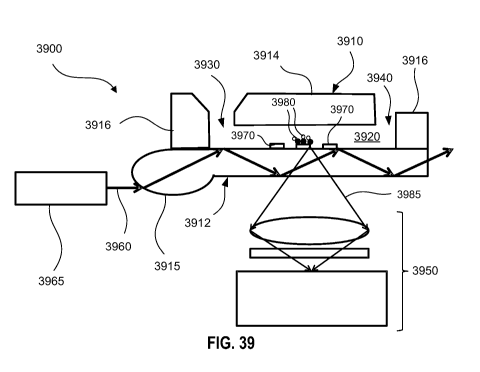
[0036] FIG. 39 provides an exemplary schematic for a sample processing and
analyte
detection system, in accordance with an embodiment.
[0037] FIG. 40 provides exemplary results for the multiplexed particle
experiment described
in Example V.
[0038] FIG. 41 provides exemplary results for the protein detection experiment
described in
Example VI.
[0039] FIG. 42 provides representative experimental results demonstrating
fluorescence
signal enhancement resulting from alignment of particle complexes, as
described in Example VII.
[0040] FIG. 43 provides exemplary results for the RNA detection experiment
described in
Example IX.
[0041] FIGS. 44 and 45 provide exemplary results for the RNA detection
experiment
described in Example X.
[0042] FIGS. 46 and 47 provide exemplary results for the HIV p24 antigen
detection
experiment described in Example XI.
[0043] It is noted that, for purposes of illustrative clarity, certain
elements in the drawings
may not be drawn to scale.
DETAILED DESCRIPTION
[0044] The embodiments described herein address the need for simplified,
integrated
sample preparation and detection systems for biological assays. Exemplary
embodiments address
major limitations in the current art, in which sample preparation and analyte
detection are
performed separately, each with multiple, time-consuming or automation-
intensive methods. Few,
if any, previously-described approaches have successfully combined sample
preparation and
detection in a single, integrated method. The approach described herein
addresses the significant
need for simplified, integrated sample preparation and detection systems for
biological assays.
7
CA 02772020 2012-02-23
WO 2011/026030 PCT/US2010/047145
[0045] Examples of analytes include nucleic acids, proteins, and cells in
complex milieu,
such as biological samples. For instance, the target analyte may be a protein
or peptide target, and
particles may be functionalized with specific binding groups such as
antibodies, Fab fragments, or
aptamers. A complex of at least two dissimilar particle types may be used for
the integrated
purification, concentration, and detection of target analytes. The multiple-
particle complex may be
formed, for example, when a target analyte forms the link between a field-
responsive particle, such
as a magnetic particle, and a signal generating particle, such a fluorescent
particle. That is, the
multiple-particle complex effectively acts as a sandwich assay.
[0046] The terms "particles" and "beads" are used interchangeably herein, and
may refer to
any of several particles of different compositions ranging in size from
approximately 0.01 to 20
micrometers in diameter. Particles may include organic materials such as, but
not limited to, latex,
polystyrene, agarose and lipids. While particles are spherical (e.g., latex
microspheres) in many
cases, the particles disclosed herein are not required to be spherical.
Particles may also include
inorganic materials such as, but not limited to, silica and other silica-based
glass compositions,
oxides including iron oxides, ceramics and semiconductors. Particles may also
be composite
constructions, such as core-shell particles (e.g., a metal or metal oxide core
with an organic polymer
shell), and polymers incorporating metal oxide subparticles therein.
[0047] FIG. 1 shows an illustration of the formation of a multiple-particle
complex by the
linking of a particle of a first type and another particle of a second type
via a target analyte, in
accordance with an embodiment. A complex 100 includes a target analyte 110,
which is shown here
as a nucleic acid strand. Target analyte 110 includes a first end sequence 112
and a second end
sequence 114. A first type particle 120 has been functionalized with a first
probe 125 (e.g., a
"capture probe"), complementary to first end sequence 112 of target analyte
110. First type particle
120 may be, for example, a field-responsive particle, such as a magnetic
particle, that has been
functionalized with a capture sequence complementary to first end sequence 112
of target analyte
110. As a particular example, first probe 125 may be a 50 nucleotide, single-
stranded DNA capture
sequence. A field-responsive particle may be any particle that responds to an
external force field
such as, but not limited to, a magnetic field, an electric field and
gravitational or sedimentation field.
[0048] Continuing to refer to FIG. 1, a second type particle 130 has been
functionalized with
a second probe ("detect probe") 135, which is complementary to second end
sequence 114 of target
analyte 110. For example, second type particle 130 may be a signal particle,
such as a fluorescent
particle, that has been functionalized with a DNA sequence complementary to
second end sequence
114. A signal particle (or a signal generating particle) may be any particle
that generates a
detectable signal, such as a luminescent particle that emits light when
excited with an appropriate
8
CA 02772020 2012-02-23
WO 2011/026030 PCT/US2010/047145
illumination source. Examples of detectable signals include, but are not
limited to, luminescence,
fluorescence, phosphorescence, chemiluminescence, light scattering and
magnetic fields. Complex
100 exhibits a combination of the characteristics of first and second type
particles 120 and 130,
respectively. For example, if first type particle 120 is a magnetic particle,
and second type particle
130 is a fluorescent particle, then complex 100 may be manipulated by
application of a magnetic
field, and also be induced to generate a fluorescent signal by application of
appropriate excitation
energy, such as light from a laser or a light-emitting diode ("LED").
[0049] In various embodiments, target analyte 110 forms a bridge between at
least two
dissimilar particles, each with distinct functionality. One particle type
(e.g., first type particle 120)
may be responsive to a force field (i.e., a field-responsive particle),
allowing the separation,
purification and/or concentration of these particles with the application of
an appropriate force
field. For example, the field-responsive particle may be a paramagnetic
particle, which is responsive
to a magnetic field from a permanent magnet or electromagnet. The field-
responsive particle may
also include other magnetic particle types. Additional types of particles
suitable for use as field-
responsive particles may be sedimenting particles, such as particles with
sufficient density relative to
the fluid density to allow sedimentation, either in a natural gravitational
field or through
centrifugation, and particles with electrophoretic mobility (i.e., particles
responsive to an applied
electric field).
[0050] Furthermore, second type particle 130 may be, for example, a latex or
glass particle
impregnated with fluorescent molecules, luminescent particles (e.g., particles
impregnated with
lanthanide chelates), light scattering particles, resonant light scattering
particles, nanoparticles,
and/or magnetic particles. Both first and second type particles 120 and 130
may require
functionalization with binding moieties that make them amenable to biological
assays. Particle
functionalization protocols are established in the art, and kits for magnetic
particle and fluorescent
particle functionalization are commercially available.
[0051] FIG. 2 shows an illustration of another approach to formation of a
multiple-particle
complex, in accordance with an embodiment. In this case, a first type particle
and a second type
particle are linked via a target analyte, where the target analyte is an
antigen such as, for example, a
protein, bacteria, or cell. A complex 200 includes a target analyte 210.
Target analyte 210 includes a
first epitope region 212 and a second epitope region 214. A first type
particle 220 has been
functionalized with a first specific-binding ligand 225, such as an antibody,
which has been selected
for having a specific affinity to first epitope region 212 of target analyte
210. First type particle 220,
again, may be a field-responsive particle, such as a magnetic particle. A
second type particle 230 has
similarly been functionalized with a second specific-binding ligand 235, which
has been selected for
9
CA 02772020 2012-02-23
WO 2011/026030 PCT/US2010/047145
having a specific affinity to second epitope region 214 of target analyte 210.
Second type particle
230 may be, for example, a signal particle, such as a fluorescent particle
that generates a fluorescent
signal by application of appropriate excitation energy.
[0052] In one embodiment, nucleic acid target is rapidly concentrated and
detected using
magnetic particles functionalized with oligonucleotide capture probes
complementary to the target
nucleic acid sequence and fluorescent particles functionalized with
oligonucleotide probes
complementary to a different section of the target sequence. Simple wash steps
may be performed
using magnetic washes, and a magnet is then used to drive particle pairs to a
detection surface
where particle complexes are quantified. FIGS. 3 - 6 are a series of drawings
illustrating an
exemplary process for such sample preparation and multiple-particle complex
formation and
detection.
[0053] First referring to FIG. 3 in conjunction with FIG. 1, a buffer 302 is
confined within a
container 304. A sample, such as blood, serum, or other biological specimen
containing a target
analyte 110, is added to buffer 302. Buffer 302 may be, for example, a lysis
buffer or a stabilization
buffer containing functionalized particles. In the exemplary process shown in
FIG. 3, buffer 302
contains first and second type particles 120 and 130, respectively, which have
been functionalized,
as previously discussed. For example, as shown in FIGS. 1 and 3, first type
particle may be a
magnetic particle, which functionalized with capture probes 125 suitable for
binding to first end
sequence 112 of the specific target analyte of interest. Also, second type
particles 130 may be a
fluorescent particle, which has been functionalized with detect probes 135
suitable for binding to
second end sequence 114 of target analyte 110.
[0054] Referring to FIG. 4, hybridization leads to the formation of multiple-
particle
complexes 100. Each one of multiple-particle complexes 100 is formed by
capture probe 125 of first
type particle 120 binding to first end sequence 112 of target analyte 110, and
detect probe 135 of
second type particle 130 binding to second end sequence 114 of target analyte
110. Unbound first
and second type particles 120 and 130, respectively, remaining in buffer 302
then are removed by
one or more "wash" steps, as shown in FIG. 5. Taking advantage of the magnetic
nature of first type
particles 120, a magnet 510 is brought into proximity of container 304 such
that multiple-particle
complexes 100 as well as unbound first type particles 120 are pulled toward
magnet 510, while
unbound second type particles 130, which are non-magnetic, remain suspended in
buffer 302. By a
series of fluid exchange (i.e., "wash") steps, substantially all of unbound
second type particles 130
may be removed from container 304. It may be noted that unbound, first type
particles 120 need
not be removed by wash steps because they do not generate a signal that is
detectable in the
detection step, which is illustrated in FIG. 6.
CA 02772020 2012-02-23
WO 2011/026030 PCT/US2010/047145
[0055] Following the wash steps, magnet 510 is removed and the remaining
multiple-
particle complexes 100 and unbound first type particles 120 are allowed to
settle at the bottom of
container 304, as shown in FIG. 6. Alternatively, multiple-particle complexes
100 and unbound first
type particles 120 may be magnetically concentrated at the bottom of container
304. Second type
particles 130, bound to target analyte 110 within multiple-particle complexes
100, are excited with
an appropriate excitation energy (not shown), and the resulting signal from
second type particles is
detected by an imaging system 610.
[0056] An alternative method of sample preparation and analyte detection
without a
"wash" step is shown in FIGS. 7-9. In this embodiment, all particles,
including multiple-particle
complexes as well as unbound first type and second type particles are present
at the bottom of
container 304, and a detection method that is sensitive only to multiple-
particle complexes is used
for target analyte detection. As shown in FIG. 7, which is similar to FIG. 3,
buffer 302 within a
container 304 contains a plurality of target analyte 110, first type particle
120 and second type
particle 130. As shown in FIG. 8 (which is similar to FIG. 4), target analyte
110 links together first and
second type particles 120 and 130, respectively, so as to form a plurality of
multiple-particle
complexes 100. In contrast to the method described in relation to FIGS. 3 - 6,
this alternative
method eliminates the wash step shown in FIG. 5. Then, as shown in FIG. 9, a
detection method
sensitive only to the presence of multiple-particle complexes 100 is used to
detect the presence of
the target analyte. An example of such a detection method is described in
Example VII below.
[0057] The processes shown in FIGS. 3 - 9 may be adapted to affect spatial
translation of
the target analyte and/or multiple-particle complexes by using the processes
in combination with a
fluidic channel and a magnetic arrangement, such as a movable set of magnets
or a plurality of
magnets that may be activated and deactivated at will (e.g., electromagnets).
An example of such a
spatial translation process, suitable for integrated sample preparation and
analyte detection, is
illustrated in FIGS. 10 - 17.
[0058] FIG. 10 shows a system 100 including a cartridge 1010, which is formed
from a
substrate 1012, an upper component 1014, and a gasket 1016 defining a fluidic
channel 1020.
Alternatively, substrate 1012 and/or upper component 1014 may include
integrally-formed side
walls (not shown), in place of gasket 1016, such that the combination of
substrate 1012 and upper
component 1014 alone defines fluidic channel 1020. Fluidic channel 1020
includes an inlet port
1030 and an outlet port 1040 such that a fluid may be introduced through inlet
port 1030 then
removed through outlet port 1040. An array of capture spots (shown as A1- A4
in FIG. 10) is
printed on substrate 1012. Capture spots may include immobilized biomolecules
such as antigens,
antibodies, proteins, peptides, glycans, or nucleic acids. various methods of
preparing printed
11
CA 02772020 2012-02-23
WO 2011/026030 PCT/US2010/047145
arrays, including contact printing, inkjet printing, piezoelectric printing,
and solenoid valve jet
printing are available. MO - M8 show different positions for the placement of
a magnet for use in
the spatial translation process. Fixed magnets may be translated to different
positions during the
assay, or electromagnets may be configured to be turned on and off in order to
create translating
magnetic fields at these positions. An imaging system 1050 may be used to
capture images of
optical signals generated at capture spots Al - A4 by excitation 1060 from a
light source 1065.
[0059] In one embodiment, referring to FIG. 11, channel 1020 is pre-filled
with a buffer
1025. A sample is then introduced at inlet port 1030. The sample contains a
combination of target
analyte 110, first and second type particles 120 and 130, and multiple-
particle complexes 100
formed by a combination of target analyte 110 linking first and second type
particles 120 and 130
therewith.
[0060] Referring now to FIG. 12, a fixed magnet or electromagnet at position
MO is
activated, then an additional amount of buffer 1025 is added at inlet port
1030. The additional
buffer causes flow through fluidic channel 1020, such that unbound second type
particles are
flushed to outlet port 140 while first type particles 120 and multiple-
particle complexes 100 are
retained upstream from the array of capture spots.
[0061] As shown in FIG. 13, a second electromagnet, located at position Ml
beneath
capture spot Al, is then activated such that the remaining first type
particles 120 and multiple-
particle complexes 100 migrate over capture spot Al. Alternatively, a fixed
magnet may be moved
from position MO to position Ml beneath capture spot Al and be activated for a
certain amount of
time (e.g., 5 seconds). The magnet is then deactivated to allow first type
particles 120 and multiple-
particle complexes 100 to freely interact with immobilized capture molecules
at spot Al. Modes of
capture molecule immobilization and binding to a capture spot are described in
the descriptions of
FIGS. 18 and 19 below. If a specific binding event occurs (e.g., antigen-
antibody, protein-protein, of
nucleic acid hybridization), then first type particles 120 and multiple-
particle complexes 100 become
bound at spot Al.
[0062] After a set amount of time (e.g., 20 seconds), an electromagnet is
activated beneath
capture spot A2 or, alternatively, the magnet shown in FIG. 13 may be moved
from position Ml to
position M2 beneath capture spot A2 then activated for a predetermined amount
of time (e.g., 5
seconds), as shown in FIG. 14. Consequently, first type particles 120 and
multiple-particle complexes
100 that did not bind to capture spot Al migrate toward capture spot A2. In
the example shown in
FIG. 14, no specific binding to spot Al occurred, and all first type particles
120 and multiple-particle
complexes 100 are magnetically transported to capture spot A2. Once the magnet
at M2 is
12
CA 02772020 2012-02-23
WO 2011/026030 PCT/US2010/047145
deactivated or removed, the unbound first type particles 120 and multiple-
particle complexes 100
are allowed to freely interact with immobilized capture molecules at capture
spot A2 for a certain
amount of time (e.g., 20 seconds). The process is then repeated for the magnet
positions M3 and
M4 corresponding to capture spots A3 and A4, respectively, as shown in FIGS.
15 and 16,
respectively. In this example, specific binding at capture spot A2 occurred,
and particle complexes
were retained at spot A2 during subsequent magnetic migration steps. Finally,
any residual first type
particles 120 and multiple-particle complexes 100 are moved away from the
capture array by
moving or activating the magnet to position M5.
[0063] In the method illustrated in FIGS. 10- 17, the combination of the
fluidic channel and
the magnet configurations allows the performance of sample preparation and
analyte detection
within a single volume. That is, the initially-added sample, as shown in FIG.
11, may include
unbound second type particles prior to introduction into channel 1020. While a
sample preparation
method, such as illustrated in FIGS. 3 - 6, may be performed separately prior
to sample introduction
into channel 1020, the fluidic channel and magnet configuration of FIG. 10
makes a separate sample
preparation optional. Such simplification is particularly desirable in
reducing the complexity of the
overall assay protocol.
[0064] In the embodiment shown in FIGS. 10 - 17, magnets at positions M6 and
M8 may be
further configured to tune the direction of the applied magnetic field in
order to alter magnetic
migration velocities through the channel. For example, optionally, a fixed
magnet or electromagnet
at position M6 may be activated at the same time as the magnet at position MO
to assist in the flow
and capture of first type particles 120 and multiple-particle complexes 100
through channel 1020, as
shown in FIG. 12. Similarly, a fixed magnet or electromagnet at position M8
may also be
simultaneously activated to assist in the flow of unbound first type particles
120 and multiple-
particle complexes 100 toward outlet port 1040, as shown in FIG. 17.
[0065] FIGS. 18 and 19 show schematics illustrating different modes of capture
molecule
immobilization and binding to a capture spot. Specific binding of multiple-
particle complexes 100
may be designed to occur via first probe 125 on first type particles 120 (FIG.
18) or via second probe
135 on second type particles 130 (FIG. 19). For illustration purposes, FIGS.
18 and 19 assume a
nucleic acid target with oligonucleotide probes on each particle type.
[0066] Referring to FIG. 18 in conjunction with FIG. 10, capture spot Al on
substrate 1012
includes first immobilized oligonucleotide probe 1910 with first end sequence
112, complementary
to the sequence of the oligonucleotide (i.e., first probe 125) immobilized on
first type particle 120.
Capture spot A2 includes second immobilized oligonucleotide probe 1920 with
another sequence
13
CA 02772020 2012-02-23
WO 2011/026030 PCT/US2010/047145
that is complementary to neither first probe 125 nor second probe 135. During
an assay such as that
described in FIGS. 10-17, multiple-particle complexes 100 will specifically
bind to capture spot Al
through first probe 125, as will unbound first type particles 120
functionalized with first probe 125.
Since capture spot A2 includes only second immobilized oligonucleotide probe
1920 with non-
complementary sequences in this example, no particles of any type bind to spot
A2.
[0067] FIG. 19 shows the alternative configuration, in which multiple-particle
complexes
100 bind through second-type particle 130. In this example, capture spot Al'
includes first
immobilized oligonucleotide probe 2010 with a non-complementary sequence,
while capture spot
AT includes second immobilized oligonucleotide probe 2020 with second end
sequence 114, which
is complementary to second end sequence 135 immobilized on second type
particle 130. During an
assay such as that described in FIGS. 10-17, multiple-particle complexes 100
and unbound second
type particles 130 will specifically bind to capture spot A2'through second
probe 135. No particles
of any type bind to spot Al' as first immobilized oligonucleotide probe 2010
includes only a
sequence that is complementary to neither first probe 125 nor second probe
135. An advantage of
performing specific binding through second type particle as shown in FIG. 20,
is that only multiple-
particle complexes are immobilized on the capture spot, assuming unbound
(i.e., free) second type
particles 130 were removed from the sample prior to introduction to fluidic
channel 1020. FIGS. 3-6
described a sample preparation method in which unbound second type particles
may be removed
from the sample for use with a capture configuration as shown in FIG. 19.
[0068] Although FIGS. 18 and 19 illustrate specific binding through
oligonucleotide probes,
it is recognized that the concepts shown in FIGS. 18 and 19 may readily be
applied to protein or
cellular targets with specific binding molecules such as peptides, proteins,
antibodies, aptamers, etc.
[0069] Referring again to FIGS. 10 - 17, cartridge 1010, after the steps shown
in FIGS. 11 -
17, may then be illuminated with excitation 1060 from light source 1065.
Consequently, second-
type particles 130, linked within multiple particle complexes 100 captured on
one or more of capture
spots Al - A4, generate a signal in response to excitation 1060 that may be
captured by imaging
system 1050 for target analyte detection.
[0070] Optionally, as shown in FIGS. 20 and 21, a wash magnet 1910 may be used
to
provide a "magnetic wash" step. For example, as shown in FIG. 20, first type
particles 120 and
multiple-particle complexes 100 may be distributed through fluidic channel
1020 such that the
particles settle onto one or more of capture spots Al - A4 simultaneously,
rather than being
translated from spot to spot in a step-wise fashion, as illustrated in FIGS.
11- 17. At least one of the
specific binding processes, as illustrated in FIGS. 18 and 19, may take place
such that certain particles
14
CA 02772020 2012-02-23
WO 2011/026030 PCT/US2010/047145
are captured on one or more of capture spots Al - A4. Wash magnet 1910 may
then be activated at
position M7 for a specific period of time (e.g., one minute) such that unbound
first type particles 120
and multiple-particle complexes 100, which have not been specifically bound to
one of capture spots
Al - A4, are removed from an imaging zone proximate to capture spots Al - A4.
For example, for
given excitation 1060 provided by light source 1065, configuration of
substrate 1012 and settings of
imaging system 1050, the imaging zone may be defined as an area that extends
less than a
micrometer into channel 1020 from the surface of substrate 1012 on which
capture spots Al - A4
have been disposed (for example, the extent of evanescent wave propagation
beyond substrate
1012 in a total internal reflection mode of illumination through substrate
1012). The removal of
unbound first type particles 120 from the imaging zone essentially functions
as a "magnetic wash,"
in which unwanted particles are removed from the imaging zone by magnetic
force. The strength of
the magnetic field may be tuned such that particles specifically-bound to a
capture spot are not
removed with the application of the magnetic field from position M7. While
four capture spots Al -
A4 are shown in FIGS. 10- 17 and 20- 21, fewer or more capture spots may be
used depending on
the particular biomolecules of interest.
[0071] Further details of the magnetic wash step shown in FIG. 18 are
illustrated in FIGS. 22
- 24. The situation shown in FIGS. 22 - 24 is similar to that shown in FIG. 18
in that first type
particles 120 are specifically bound to capture spot Al, while none of the
particles in the sample is
bound to capture spot A2. Upon application of magnetic force from above (e.g.,
from a magnet in
position M7 as shown in FIG. 21), the unbound particles and multiple-particle
complexes are
removed from the surface of substrate 1012, as shown in FIG. 23. Provided that
the magnetic field
strength is not strong enough to remove specifically bound particles, as the
magnetic wash step
results in specifically bound particles on a capture spot with very low non-
specific particle
background binding (FIG. 24).
[0072] In another embodiment, particle complexes such as those shown in FIGS.
1 and 2
may be separated from free fluorescent particles using a simple mechanical
translation. FIGS. 25 -
27 illustrate an exemplary approach. When a sample, including a target
analyte, is introduced to a
solution containing functionalized first type particles 120 and functionalized
second type particles
130, multiple-particle complexes 100 are formed, as shown in FIG. 25 (FIG. 25
is similar to earlier-
described FIGS. 4 and 8). In certain cases, it is necessary to physically
separate free functionalized
second type particles 130 (e.g., free fluorescent particles) from multiple-
particle complexes 100.
This separation may be performed by using a cartridge 2610, which is formed of
a substrate 2612, an
upper component 2614, and a gasket 2616 collectively defining a fluidic
chamber 2620. Fluidic
chamber 2620 is filled with a buffer 2625. Multiple-particle complex 100,
first type particle 120 and
CA 02772020 2012-02-23
WO 2011/026030 PCT/US2010/047145
second type particle 130 are introduced to fluidic chamber 2620, as
illustrated in FIG. 26. For a thin
channel device (e.g., channel height < 0.2 millimeters), convective mixing is
minimal and the cluster
of particles generally remains near the inlet port. A magnet 2650 exerts a
magnetic force such that
field-responsive particles (e.g., first type particle 120 and multiple-
particle complex 100) are pulled
toward magnet 2650. Translation of magnet 2650 (or activation of
electromagnets) may
subsequently be used to move multiple-particle complexes 100 and first type
particles 120 to a
desired location, as shown in FIG. 27. This process provides a physical
separation of the confounding
free first type particles 120. Multiple-particle complexes 100 at the desired
location may then be
analyzed by an appropriate detection method, such as fluorescence imaging.
[0073] In another embodiment, high index of refraction particles may be used
to create
enhanced optical detection signals, as illustrated in FIGS. 28 - 37. For
example, a directional
luminescent signal enhancement with high index of refraction particle -
fluorescent particle
complexes may be obtainable. A magnetic particle may act as a high index of
refraction spherical
lens, which serves to effectively focus illumination radiation onto the
luminescent particle.
Alternatively, the magnetic particle spherical lens may collect and focus
light signal emitted from the
luminescent particle.
[0074] FIGS. 28 - 32 show different orientations of multiple-particle complex
100 with
respect to an illuminating field 2810, represented by arrows. First type
particle 120 may be formed
of a combination of materials such that so as to provide a lensing effect,
thereby focusing a portion
of illuminating field 2810 that is transmitted therethrough. For example,
first type particle may be a
polystyrene-core particle impregnated or coated with a magnetic component,
such as magnetite
(Spherotech). Then, the amount of illuminating field 2810 incident on second
type particle 130,
which may be configured to generate a detectable signal in response to
illumination, depends on the
orientation of second type particle 130 with respect to first type particle
120. For example, as
shown in FIGS. 28 - 30, when second type particle 130 is "upstream" of first
type particle 120 within
illuminating field 2810, then second type particle 130 is illuminated in the
same way as if it were not
part of multiple-particle complex 100. However, the orientation of multiple-
particle complex 100
may be such that first type particle 120 focuses illuminating field 2810 away
from second type
particle 120 (see FIG. 31) such that second type particle 110 receives much
less illumination than in
the cases shown in FIGS. 28 - 30. Alternatively, as shown in FIG. 32, second
type particle 120 may be
within a region in which illuminating field 2810 is focused by first type
particle 120 such that second
type particle 120 is more intensely illuminated than in other orientations of
multiple-particle
complex 100.
16
CA 02772020 2012-02-23
WO 2011/026030 PCT/US2010/047145
[0075] Additionally, as shown in FIGS. 33 - 37, the signal generated by second
type particle
130 may also be affected by the lensing effects imparted by first type
particle 120. Consequently,
for the same amount of signal 3310 (indicated by arrows) generated by second
type particle 130, the
amount of signal 3310 that reaches an observer 3320 depends on the orientation
of multiple-particle
complex 100. For example, as shown in FIG. 33, when first type particle 120 is
directly in the path of
signal 3310 between second type particle 130 and observer 3320, first type
particle 120 may refract
signal 3310 so as to intensify the amount of signal 3310 that reaches observer
3320. Alternatively,
multiple-particle complex 100 may be oriented such that first type particle
120 refracts signal 3310
away from observer 3320, thereby reducing the amount of signal 3310 that
reaches observer 3320
(see FIGS. 34 - 37). The focusing and light collection effects are
demonstrated experimentally in
EXAMPLE VII discussed below.
[0076] Both the focusing and light collection effects may be utilized in
detection systems to
significantly improve the sensitivity of multiple-particle complex detection.
When properly oriented
relative to a detector (e.g., a CCD or CMOS camera), the measured luminescent
signal may be
significantly enhanced relative to the signal from an isolated luminescent
particle. For instance,
multiple-particle complexes may be allowed to tumble in solution. Depending on
orientation of the
multiple-particle complex relative to the illumination source and detector,
this tumbling effect may
significantly alter the illumination intensity incident at the luminescent
particle. Similarly, during
luminescence emission, the magnetic particle spherical lens may serve to focus
or direct light in a
direction linked to the orientation of the particle complex.
[0077] Due to the highly directional nature of the signal enhancement effect
illustrated in
FIGS. 28 - 37, tumbling multiple-particle complexes will appear to flash when
visualized with an
imaging detector such as a CMOS or CCD camera. Free fluorescent particles
(i.e., fluorescent
particles that are not linked to a magnetic particle in a multiple-particle
complex) exhibit no such
flash effect, and instead exhibit a steady state fluorescence emission. When
attached to magnetic
particles in a multiple-particle complex, the flashing particles (when
captured in their "bright"
orientation) show fluorescence emission that appears to be physically larger
and more intense than
the free fluorescent particles. Furthermore, particle pairs may be
intentionally oriented relative to a
detector in order to increase emitted light detection. The particle pairs may
be oriented using, for
example, magnetic fields and fluid forces.
[0078] It may be noted that this localized particle lensing effect is
significantly enhanced via
the use of high refractive index particles. In an embodiment, magnetic polymer
microspheres
exhibit an effective index of refraction higher than non-magnetic polymer
microspheres. For
instance, incorporation of magnetic iron within the microsphere may increase
the effective index of
17
CA 02772020 2012-02-23
WO 2011/026030 PCT/US2010/047145
refraction of the microsphere, thus yielding stronger focusing effects. For
the size range of particles
described in this embodiment, the magnetic polymer microspheres give
significant signal
enhancement relative to non-magnetic polymer microsphere of the same diameter.
This signal
enhancement effect is experimentally demonstrated in EXAMPLE VIII discussed
below.
[0079] Several examples of implementations of exemplary embodiments of the
present
technology are disclosed herein. These descriptive examples are not intended
to be limiting, but
rather illustrative. Specific quantities and chemicals discussed herein are
merely representative, as
will be appreciated by those skilled in the art.
EXAMPLE I: Rapid, Specific DNA Target Concentration and Detection
[0080] This example of the present technology demonstrates the detection of
target DNA
using an oligonucleotide sandwich assay and a dual particle capture and detect
format. Magnetic
particles were functionalized with a 50 nucleotide single stranded DNA capture
sequence ("capture
probe") specific to a section of the DNA target. The "detect probe" was a 50
nucleotide biotinylated
DNA sequence specific to a section of DNA target adjacent to the capture
sequence. In the presence
of DNA target, the capture and detect probes specifically hybridize to
adjacent sections of the target,
creating the sandwich. A particle complex is created by adding avidin-
functionalized fluorescent
particles, which bind to the biotinylated detect probe. Nucleic acid probe
sequences are provided in
Table 1, and experimental details are provided here. In one instance, target
analyte / particle
complexes may be delivered to a detection surface via passive sedimentation by
ambient gravity. In
another approach, target analyte / particle complexes may be delivered to a
detection surface via
active sedimentation in a centrifuge. In another approach, target analyte /
particle complexes may
be translated along a two dimensional surface to an analytical region by
applying magnetic force
from under the two dimensional surface and moving the magnet and thus the
particle complexes to
the analytical region.
[0081] Magnetic particle functionalization. Magnetic particles were coated
with an amine-
functionalized DNA probe using the following protocol. 100 microliters of a 10
mg/ml solution of 1
micrometer diameter magnetic particles (Dynabead MyOne Carboxylic Acid,
Invitrogen) were
transferred to a 1.7 ml micro-centrifuge tube. The tube was placed in a
magnetic separator
(Invitrogen Dynal) to concentrate the beads to the side wall of the tube. The
liquid was removed
and particles were re-suspended in water. This wash step was repeated with
water and then
particles were suspended in 200 microliters of 0.1M MES (2-
morpholinoethanesulfonic acid, Fluka),
pH 5.2. 100 microliters of 10 mg/ml 1-ethyl-3-[3-dimethylaminopropyl]
carbodiimide hydrochloride
18
CA 02772020 2012-02-23
WO 2011/026030 PCT/US2010/047145
(EDC, Pierce) and 100 microliters of 10mg/ml sulfo-N-hydroxysuccinimide (Sulfo-
NHS, Pierce) were
added to the magnetic particle solution. The solution was mixed for 30 minutes
by rotating. The
tube was then placed in the magnetic particle separator and the liquid was
removed. Particles were
then suspended in a 100 microliter solution of 500 micromolar amine-modified
capture probe (see
Table 1) in 0.1M phosphate buffer, pH 8Ø The solution was mixed for 3 hours
at room temperature
on a rotator. The tube was then placed in the magnetic separator and the
liquid was removed. The
particles were washed 3 times with 1X PBS, 0.05% Tween20 (PBST) using the
magnetic separator for
each step. Particles were then re-suspended in bead buffer ("BB"), which
contains 1X PBS, 0.3 molar
sodium chloride (NaCl), 20 micrograms/ml herring sperm DNA (Sigma-Aldrich),
200 micrograms/ml
bovine serum albumin (BSA, Sigma-Aldrich) and 0.05% Tween20 (Pierce).
Concentration of particles
at this point was 1 mg/ml. Functionalized particles were stored at 4 C.
[0082] Fluorescent particle functionalization. Fluorescent particles (Thermo,
Dark Red, 0.39
micrometer, 2% wt/vol) were functionalized by mixing 100 microliters of
particle stock solution with
100 microliters of 0.2 mg/ml NeutrAvidin (Pierce) in 0.2 molar sodium
phosphate for 4 hours at 4 C.
200 microliters of BB were added. The solution was transferred to a 0.1
micrometer microfiltration
centrifuge tube (Millipore) and centrifuged for 8 minutes at 6000 rpm (Fisher
Scientific Accuspin
Microl7 centrifuge). Particles were re-suspended in bead buffer and the
filtration step was
repeated two more times (i.e., three washes total). The particles were then re-
suspended in bead
buffer and stored at 4 C at a concentration of 0.1% w/v.
[0083] Target DNA Capture. Target DNA was captured on capture probe-modified
magnetic
particles. Biotinylated detect probe was added during hybridization.
NeutrAvidin-coated
fluorescent particles were added after hybridization to complete the full
sandwich.
[0084] Synthetic target DNA C05 d100 tar (IDT, Table 1, Example I) is derived
from a portion
of the influenza H1N1 genome. The capture oligonucleotide (i.e., capture
probe) is complementary
to the 5'-end of target DNA and was synthesized by Integrated DNA
Technologies, Inc. (IDT, Inc.)
with a C6-amine 3' modification (capture probe c05 5pcomp 50 in Table 1). The
biotinylated detect
oligonucleotide (detect probe) was complementary to the 3'-end of target DNA
and was synthesized
by IDT, Inc. as the 5' C6-amine derivative (detect probe c05 3pcomp 50 in
Table 1). Biotin was
conjugated to this sequence by reaction with Sulfo-NHS-LC-Biotin (Pierce).
[0085] Assay protocol. Dilutions of target DNA were mixed with 2E6 capture
probe-
modified magnetic particles in hybridization buffer ("HB"), (3X SSPE (Saline-
Sodium Phosphate-
Ethyl enediaminetetraacetic acid ("EDTA")) buffer0.1% sodium dodecyl sulfate
("SDS"), 100
microgram/ml BSA and 20 microgram/ml of herring sperm DNA ("hsDNA"))
containing 2 nanomolar
19
CA 02772020 2012-02-23
WO 2011/026030 PCT/US2010/047145
biotinylated detect probe and mixed on a rotating heat block at 1100rpm at 55
C for 2 hours,
allowing formation of the particle/capture probe/target/detect probe complex.
[0086] Particle complexes were then washed as follows using a permanent magnet
and
fluid exchange. Supernatant was removed and particles were re-suspended in 3X
SSPE, 0.1% SDS
(1X). This was followed by two washes (supernatant exchange) with PBSHT (1X
PBS, 500 millimolar
NaCl, 2mg/ml BSA, 20ug/ml hsDNA, 0.05% Tween20). The particles were then
suspended in 100
microliters of PBSHT, and 2E8 NeutrAvidin-fluorescent particles were added.
The solutions were
mixed on a rotator at room temperature for 15 minutes to allow biotin-
NeutrAvidin binding.
Magnetic-fluorescent particle complexes are formed in this step, with target
DNA forming the link
between the particles.
[0087] Particle complexes were washed 3X with PBSHT by magnetic isolation and
removal
of supernatant with final resuspension in 100 microliters of PBSHT. The entire
volume of each
reaction was transferred to separate wells of a 384 well plate and a bar
magnet was used to draw
the particle complexes to the bottom surface of the wells This wash procedure
removes unbound
fluorescent particles so that the only remaining fluorescent particles are
those complexed with
magnetic particles through interaction with the target.
[0088] Particle complexes were quantified by imaging on an epifluorescence
microscope
(Olympus IX-71) equipped with a 20X objective and Cy5 filters. Particle
complexes in the images
were counted automatically using a particle counting tool developed in the
open-source software
Images. Results are presented in FIG. 38, showing the resulting titration
curve, with limit of
detection at approximately 1 femtomolar target.
[0089] In the present example, 1 micrometer diameter magnetic particles were
used as an
exemplary demonstration. Alternatively, magnetic particles in the diameter
size range of 0.01 to 20
micrometers may be used. Alternatively, magnetic particles in the diameter
size range of 0.2 to 10
micrometers may be used. Alternatively, magnetic particles in the diameter
size range 0.3 to 6
micrometers may be used. It is also noted that magnetic particle size
distributions may be
monodisperse. Alternatively, a range of magnetic particle sizes may be used
simultaneously. It is
also noted that non-spherical magnetic particles may be used.
[0090] In the present example, commercially available monodisperse polymer
shell
superparamagnetic particles were used as an exemplary demonstration.
Alternative magnetic
particle types may be used in this invention. Alternative magnetic particle
matrix materials include
latex, polystyrene, agarose, and other polymers, silica and silica-based glass
compositions, oxides
including iron oxides, and ceramics. Magnetic particles may also be composite
constructions, such
CA 02772020 2012-02-23
WO 2011/026030 PCT/US2010/047145
as core-shell particles (e.g., metal or metal oxide core with organic polymer
shell), and polymers
incorporating metal oxide subparticles.
[0091] In the present example magnetic particle functionalization was
performed using
amine-modified oligonucletides with EDC-NHS ester chemistry as an exemplary
demonstration.
Alternative, amine-reactive coupling chemical reactions include those based on
isothiocyanates,
isocyanates, acyl azides, sulfonyl chlorides, aldehydes, glyoxals, epoxides,
oxiranes, carbonates,
arylating agents, imidoesters, carbodiimides, and anyhydrides. As an
alternative to amine-modified
oligonucleotides, thiol-modified oligonucleotides may be used. Alternative
thiol-reactive coupling
chemical reactions that may be used include those based on haloacetyl and
alkyl halide derivatives,
maleimides, aziridines, acrylolyl derivatives, arylating agents, and thiol-
disulfide exchange reagents.
As another alternative to amine-modified oligonucleotides, carboxylate-
modified oligonucleotides
may be used. Alternative carboxylate-reactive coupling chemical reactions that
may be used include
diazoalkanes and diazoacetyl compounds, carbonyldiimidazole, and
carbodiimides. As another
alternative to amine-modified oligonucleotides, hydroxyl-modified
oligonucleotides may be used.
Alternative hydroxyl-reactive coupling chemical reactions that may be used
include epoxides and
oxiranes, carbonyldiimidazole, N,N'-disuccinimidyl carbonate, alkyl halogens,
isocyanates, or
oxidation chemistries. As another alternative to amine-modified
oligonucleotides, aldehyde-
modified or ketone-modified oligonucleotides may be used. Alternative aldehyde-
reactive or
ketone-reactive coupling chemical reactions that may be used include hydrazine
derivatives, Schiff
base formation, reductive amination, and Mannich condensation. As another
alternative to amine-
modified oligonucleotides, photo-reactive oligonucleotides may be used.
Alternative photoreactive
coupling chemical reactions that may be used include aryl azides and
halogenated aryl azides,
benzophenones, diazo compounds, and diazirine derivatives.
[0092] In the present example, 0.39 micrometer diameter fluorescent particles
were used
as an exemplary demonstration. Alternatively, fluorescent particles in the
diameter size range of
0.01 to 20 micrometers may be used. Alternatively, fluorescent particles in
the diameter size range
of 0.2 to 10 micrometers may be used. Alternatively, fluorescent particles in
the diameter size range
0.3 to 6 micrometers may be used. It is also noted that fluorescent particle
size distributions may be
monodisperse. Alternatively, a range of fluorescent particle sizes may be used
simultaneously. It is
also noted that non-spherical fluorescent particles may be used.
[0093] The Dark Red (Thermo) fluorescent particle product used in the example
had
excitation / emission wavelengths centered at 640/660nm. An alternative
fluorescent dye may be
used in the blue part of the spectrum (excitation 360 to 420 nm and emission
420 to 480 nm); green
part of the spectrum (excitation 450 to 500 nm, emission 500 to 540 nm); or
red part of the
21
CA 02772020 2012-02-23
WO 2011/026030 PCT/US2010/047145
spectrum (excitation 540 to 590 nm, emission 590 to 640 nm). Another
alternative fluorescent dye
may be used in the infrared part of the spectrum, with emission wavelengths >
700 nm such as the
products from Li-Cor Biosciences. The fluorescent particles used in the
present example were based
on organic dye fluorophores. Alternative luminophores may be used, including
lanthanides such as
europium, erbium, and terbium based emitters, as well as semiconductor based
emitters, such as
quantum dots.
[0094] In the present example, the detect probe was a biotinylated
oligonucleotide that
was subsequently bound to a NeutrAvidin fluorescent particles. Alternatively,
the fluorescent
particle in this example may be modified with streptavidin or avidin.
Alternatively, the fluorescent
particle in this example may be coupled directly to the detect oligonucleotide
prior to the assay.
Alternative fluorescent particle functionalization chemistries are the same as
those listed above for
magnetic particle functionalization.
[0095] The DNA target In the present example was a synthetic 100 nucleotide
sequence
used as an exemplary demonstration. Alternatively, the DNA target may be any
DNA molecule with
a minimum length of 30 nucleotides. Alternatively, the DNA target may be 30 to
5000 nucleotides
long.
[0096] Capture and detect probe lengths used in this example were 50
nucleotides in length
with six carbon linkers. Alternatively, oligonucleotide probes may be 10 to
100 nucleotides in length.
Alternatively, oligonucleotide probes may be 20 to 70 nucleotides in length.
[0097] The hybridization reaction In the present example was performed using a
rotating
heat block at 1100 rpm at 55 C for 2 hours as an exemplary demonstration.
Alternatively, the
hybridization reaction may be performed without mechanical mixing (rotating).
Alternatively, the
hybridization reactions may be performed in the temperature range 4 to 65 C.
Alternatively, the
hybridization reactions may be performed in the temperature range 25 to 55 C.
EXAMPLE II: Rapid, Specific RNA Target Detection with Magnetic Concentration
to Detection
Surface
[0098] Example II demonstrates detection of RNA target using the methods of
Example 1,
except that synthetic RNA target (Thermo Scientific, Sequence PrP 1013-27-1,
Table 1) was used at
100 picomolar with detect probe at 20 nanomolar.
[0099] Magnetic particles used for full sandwich detection were covalently
linked with DNA
probe (IDT, Table 1, Example II Capture Probe PrP 1013-27-5) as described
above. Control magnetic
22
CA 02772020 2012-02-23
WO 2011/026030 PCT/US2010/047145
particles were covalently loaded with DNA probe complementary to the 5'-end of
the Target RNA
(Table 1, Example II Control Probe NA-H1N1-6 3p30). Target hybridizes to the
Control Probe
particles but does not generate signal because the biotinylated detect probe
is also complementary
to the 5'-end of the Target RNA. Detect probe complementary to the 5'-end of
the target was
purchased from IDT with a biotin on the 3'-end and a dT-10 spacer (Table 1,
Example II Detect Probe
NA-H1N1-6 3p30 biotin).
[00100] A total of four different conditions were tested in this experiment:
1) specific
capture probe and RNA target (positive sample); 2) mismatch capture probe and
RNA target, to look
for non-specific hybridization; 3) specific capture probe and no RNA target;
and 4) mismatch capture
probe and no RNA target. The last two conditions assess non-specific particle-
particle interactions.
[00101] The assay protocol was as described in Example I. Each particle
suspension was
transferred to a microplate well and imaged on the inverted fluorescence
microscope as described
above. No signal was observed in wells with zero RNA or mismatch probes, while
the wells with 100
picomolar RNA target and complementary capture and detect probes registered
substantial
fluorescent bead counts.
[00102] The variations described above, with respect to Example I, are also
applicable to the
present example.
EXAMPLE III: Rapid, Specific DNA Target Detection with Magnetic Concentration,
Specific
Microarray Surface Capture, and Magnetic Wash
[00103] Example III demonstrates rapid hybridization followed by selective
surface binding
to an array of capture spots on a microarray surface. This experiment used the
same DNA target
sequence, capture probe, magnetic particles and biotinylated probes as in
Example I.
[00104] Four amine-functionalized probes were spotted onto a custom-activated
assay
device substrate using a Bio-Dot non-contact microarrayer robot. For this
example, the device
substrate was a cyclic olefin polymer (COP) planar waveguide, approximately
70mm x 25mm x 1mm
with an integrated light coupling lens. Custom activation was by first
performing an oxygen plasma
treatment on the COP waveguide followed by silanization with (3-
glycidoxypropyl) triethoxysilane to
create an amine-reactive surface activated with epoxy groups. Alternative
device substrates include
transparent planar components made of glass, ceramics, or polymers such as
polystyrene or acrylic.
Alternative silanization reagents include aminopropyl silanes, aldehyde
silanes, vinyl silanes, vinyl
sulfone silanes, acrylate silanes, methacrylate silanes, mercapto silanes,
hydroxyl silanes, carboxy
23
CA 02772020 2012-02-23
WO 2011/026030 PCT/US2010/047145
silanes, azido silanes. Alternatively, surface activation could be via on-
surface polymerization or
polymer grafting, including with polyethylene glycol polymers with reactive
end groups.
[00105] Arrays were printed with 3 spots of each probe for a 3 X 4 array. One
of the four
surface capture probes was complementary to the probes immobilized on the
magnetic particles.
The other three surface capture probes were non-complementary mismatches. All
surface capture
probes were purchased from IDT with 3'-amine linkers and a dT-9 spacer and are
listed in Table 1,
Example Ill.
[00106] Three samples were prepared in 1.5 ml micro-centrifuge tubes
containing 1 milliliter
of HB, 1E7 magnetic particles loaded with capture probe as described above,
and 5 nanomolar
biotinylated detect probe. Target DNA was added to give concentrations of 200
femtomolars and 20
femtomolars. The third sample tube contained no target DNA (zero control).
[00107] Samples were mixed for 1hr at 55 C on a thermomixer (Eppendorf) at
1200 rpm.
Particles were then rinsed once with HB and twice with BB. Particles were then
suspended in 90
microliters of BB. 10 microliters of NeutrAvidin-modified fluorescent
particles were added for a
concentration of 5E8 fluorescent particles per sample. Samples were rotated
end-over-end on a
rotator (Barnstead/Thermolyne Labquake) for 15 minutes, rinsed two times with
BB using magnetic
separation, and suspended in approximately 4 microliters of BB.
[00108] To perform the assay, a cartridge assembly, similar to that
illustrated in FIGS. 10 -
17, was used. In particular, a plastic microarray substrate was assembled into
a plastic fluidic upper
component with a pressure sensitive adhesive gasket, defining a fluidic
channel above the array.
The channel was pre-filled with 100 microliters of BB. Two microliters of
sample was added to the
inlet of the flow channel. An electro-magnet was placed at a location
approximately 2 mm upstream
of the microarray (e.g., position MO), power to the magnet was turned on to
12V and 200 microliters
of BB was added to the inlet. The addition of BB caused flow through the
channel, while the
magnetic particles were concentrated to the location of the magnet upstream
from the microarray
(as shown in FIG. 12). The magnet was then turned off and moved to a position
directly beneath the
first row of spots (C05-TR1SC specific spots; position M1 as shown in FIGS. 10
and 13). The magnet
was turned on for approximately 5 seconds at a power of 6V DC (2 amp power
supply). The particles
migrated over the first row of spots and the magnet was then turned off. After
20 seconds, the
magnet was placed under the second row of spots (C18-TR1SC; position M2 as
shown in FIGS. 10 and
14) and turned on (6V) for 5 seconds. This procedure was repeated until the
particles had been
positioned over each row of spots. The slide was then imaged on the
fluorescence microscope as in
previous experiments.
24
CA 02772020 2012-02-23
WO 2011/026030 PCT/US2010/047145
[00109] After initial imaging, a bar-shaped magnet was placed above the
microarray (e.g., at
position M7 as shown in FIG. 21) for 1 minute. This application of magnetic
force functions as a
"magnetic wash," as earlier discussed in relation to FIGS. 20 - 24. That is,
magnetic particles that are
not specifically bound to an array spot migrate up through channel and out of
the imaging zone, thus
magnetically washing non-specifically adsorbed particles. The strength of the
magnetic field may be
tuned such that specifically-bound particles are not removed due to the
application of the magnetic
field. The cartridge was imaged with an imaging system, then particle pairs at
each capture spot per
sample were enumerated using image analysis software (Images). The resulting
image analysis
yielded specific signal on the cognate specific array spots and very little
signal on the mismatch
spots.
[00110] The variations described above, with respect to Example I, are also
applicable to the
present example.
EXAMPLE IV: Rapid, Specific RNA Target Detection with Waveguide-Based
Fluorescence Detection
[00111] In this example, specific particle complex detection is demonstrated
in the context
of a planar waveguide based detection system. The materials and general method
used in this
experiment were the same as those described in Example II. Three samples were
run: 1) a 10
picomolar target sample; 2) a 100 femtomolar target sample; and 3) a zero
target control. As in
other experiments, the zero target control had very few particle pairs when
imaged in the bottom of
a microtiter plate well on microscope. The 10 picomolar target sample was then
used to test
capture of the particle pairs on a microarray. The microarray included 3
different capture probes, as
described in Table 1, Example IV.
[00112] The slide was imaged with waveguide illumination using the apparatus
shown
schematically in FIG. 39. As shown in FIG. 39, a sample preparation and
detection system 3900
includes a cartridge assembly 3910, which includes a planar waveguide 3912,
with a refractive
volume 3915, an upper component 3914, and gasket 3916 defining a fluidic
channel 3920. Fluidic
channel 3920 includes an inlet port 3930 and an outlet port 3940. System 3900
further includes an
imaging system 3950, which may in turn include, for example, one or more
refractive elements,
diffractive elements, reflective elements, filters and sensors. System 3900
also includes excitation
energy 3960 (represented by an arrow) provided by an excitation source 3965.
Excitation source
3965 may be, for instance, a laser, an LED or other suitable source of
excitation energy. As shown in
FIG. 39, an array of capture spots 3970 is affixed to a surface of planar
waveguide 3912 within fluidic
channel 3920 such that target analyte (or multiple-particle complexes 3980
containing the target
CA 02772020 2012-02-23
WO 2011/026030 PCT/US2010/047145
analyte) may be captured at one or more capture spots 3970. In experiment,
particle complexes
were only detected on the specific NA-H1N1-6 3p30 COMP-NH2 spots.
[00113] The variations described above, in reference to Examples I and III,
are also applicable
to the present example.
EXAMPLE V: Multiplexed Rapid, Specific DNA Target Detection with Specific
Microarray Capture
[00114] In another embodiment, a cocktail of particle pairs is added to a
sample containing a
plurality of different target analytes. Target analyte / particle complexes
are added to a flow
chamber including an array of capture spots specific for different particle
probes, as described in
Example IV. Signal measured on the capture spots indicate the presence and
amount of target
analyte in the original solution.
[00115] This example demonstrates the use of a cocktail of functionalized
particles in the
context of target detection. A cocktail of particles were prepared with probes
for four possible
nucleic acid targets (see Table 1, Example V). For each potential target, the
cocktail contained
magnetic particles with specific capture probe and a biotinylated detect
probe. Each magnetic
particle type was at a concentration of 2E+06 particles/ml and each
biotinylated probe was at 10
nanomolar concentration. Thus, there were four magnetic bead capture sequence
types and four
biotinylated detect sequence types, for a total of eight different probe
sequences in the cocktail.
[00116] Substrates were prepared by printing a microarray with sequences
complementary
to the probes on the magnetic particles (sequences provided in Table 1;
capture configuration
shown in FIG. 18).
[00117] The assay was performed by adding one (sequence C05) of the four
possible targets
at a concentration of 100 femtomolars. Assay steps and microarray were same as
in Example III.
The processed substrate was imaged using a fluorescent microscope and particle
complexes were
enumerated using image analysis software (Image J). Representative results are
provided in FIG. 40.
Results show that signal is strongest on the correct complementary spot.
Mismatch spots show
minimal signal relative to off-spot background.
[00118] The variations described above, with respect to Examples I and III,
are also
applicable to the present example.
EXAMPLE VI: Detection of Protein Target Using Particle Complex Approach
26
CA 02772020 2012-02-23
WO 2011/026030 PCT/US2010/047145
[00119] This example demonstrates that the system may be used to detect
protein targets.
In this example the target is an antibody. 200 microliters of Dynabeads MyOne
Streptavidin T1 (Life
Technologies) were rinsed with 100 millimolar phosphate, with pH of 7.2, using
magnetic separation
in a 1.7m1 micro-centrifuge tube, and then suspended in 200 microliters of
phosphate buffer with a
pH of 7.2. 20 microliters of 1mg/ml biotinylated donkey anti-rabbit IgG was
added to the particles,
which were mixed for 1 hour on a thermomixer at room temperature and 900 rpm.
Particles were
then rinsed four times with PBT (1XPBS, 10mg/ml BSA, 0.05% Tween 20) using
magnetic separation.
[00120] 100 microliters of fluorescent particles (Duke Sci., FR3040PA, 0.39um
Dark Red
Fluorescent polystyrene, 2%w/v) were loaded with 20u1 of a mixture of
ovalbumin (OVA) and bovine
serum albumin (BSA) at a 1:5 ratio (1 mg/m1 OVA : 5 mg/m1 BSA). The OVA/BSA
solution was added
to the particles and the mixture was incubated overnight at 4 C, then rinsed
four times over a 0.1
micrometer spin filter (Amicon) with PBT. For each rinse, 400 microliters of
PBT buffer were added
and the filter tube was centrifuged at 5000 rpm for 5min. Flow through was
discarded and another
400 microliters of PBT buffer were added to the upper chamber containing the
particles. Particles
were then suspended in 200 microliter PBT to yield a 1% w/v suspension.
[00121] The analyte for this assay was rabbit anti-ovalbumin IgG. 1:4 serial
dilutions of
rabbit anti-ovalbumin were prepared in BB to make target solutions of 128, 32,
8, 2, 0.5 and 0 pg/m1
[00122] Assay steps. 1 microliter of magnetic particles (10mg/ml stock) was
added to each
800 microliter sample in a 1.7m1 micro-centrifuge tube. The samples were mixed
for one hour at
room temperature (Barnstead/Thermolyne labquake). Particles were then
separated via magnetic
separation and supernatant removed. 100 microliters of BB were added and 10
microliters of a 1:10
dilution of ovalbumin modified fluorescent particles were added, and the
reaction was mixed on a
rotator for 15 minutes. 200 microliters of BB were added, and the tubes were
placed in a magnetic
separator and 99% of the supernatant was removed. 200 microliters of BB were
then added and
samples were transferred to a 96-well plate. A hand-held magnet was used to
concentrate the
magnetic particles and magnetic particle-fluorescent particle pairs on the
bottom of the well.
Sample wells were then imaged on a fluorescent microscope. Representative
results are provided
in FIG. 41. This preliminary experiment shows a detection limit of
approximately 10 picograms/m1
antibody target.
[00123] In the present example, 1 micrometer diameter magnetic particles were
used as an
exemplary demonstration. Alternatively, magnetic particles in the diameter
size range of 0.01 to 20
micrometers could be used. Alternatively, magnetic particles in the diameter
size range of 0.2 to 10
27
CA 02772020 2012-02-23
WO 2011/026030 PCT/US2010/047145
micrometers could be used. Alternatively, magnetic particles in the diameter
size range 0.3 to 6
micrometers could be used. It is also noted that magnetic particle size
distributions may be
monodisperse. Alternatively, a range of magnetic particle sizes could be used
simultaneously. It is
also noted that non-spherical magnetic particles could be used.
[00124] In the present example, commercially available monodisperse polymer
shell
superparamagnetic particles were used as an exemplary demonstration.
Alternative magnetic
particle types could be used in this invention. Alternative magnetic particle
matrix materials include
latex, polystyrene, agarose, and other polymers, silica and silica-based glass
compositions, oxides
including iron oxides, and ceramics. Magnetic particles may also be composite
constructions, such
as core-shell particles (e.g., metal or metal oxide core with organic polymer
shell), and polymers
incorporating metal oxide subparticles.
[00125] In the present example magnetic particles were functionalized with
streptavidin to
provide immobilization of biotinylated antibodies. Several alternatives to
biotin-streptavidin binding
could be used for protein-particle conjugation. Alternative, amine-reactive
coupling chemical
reactions include those based on succinimidyl esters, such as NHS,
isothiocyanates, isocyanates, acyl
azides, sulfonyl chlorides, aldehydes, glyoxals, epoxides, oxiranes,
carbonates, arylating agents,
imidoesters, carbodiimides, and anyhydrides. Alternative thiol-reactive
coupling chemical reactions
that could be used include those based on haloacetyl and alkyl halide
derivatives, maleimides,
aziridines, acrylolyl derivatives, arylating agents, and thiol-disulfide
exchange reagents. Alternative
carboxylate-reactive coupling chemical reactions that could be used include
diazoalkanes and
diazoacetyl compounds, carbonyldiimidazole, and carbodiimides. Alternative
hydroxyl-reactive
coupling chemical reactions that could be used include epoxides and oxiranes,
carbonyldiimidazole,
N,N'-disuccinimidyl carbonate, alkyl halogens, isocyanates, or oxidation
chemistries. Alternative
aldehyde-reactive or ketone-reactive coupling chemical reactions that could be
used include
hydrazine derivatives, Schiff base formation, reductive amination, and Mannich
condensation.
Alternative photoreactive coupling chemical reactions that could be used
include aryl azides and
halogenated aryl azides, benzophenones, diazo compounds, and diazirine
derivatives.
[00126] In the present example, 0.39 micrometer diameter fluorescent particles
were used
as an exemplary demonstration. Alternatively, fluorescent particles in the
diameter size range of
0.01 to 20 micrometers could be used. Alternatively, fluorescent particles in
the diameter size range
of 0.2 to 10 micrometers could be used. Alternatively, fluorescent particles
in the diameter size
range 0.3 to 6 micrometers could be used. It is also noted that fluorescent
particle size distributions
may be monodisperse. Alternatively, a range of fluorescent particle sizes
could be used
simultaneously. It is also noted that non-spherical fluorescent particles
could be used.
28
CA 02772020 2012-02-23
WO 2011/026030 PCT/US2010/047145
[00127] The Dark Red (Thermo) fluorescent particle product used in the example
had
excitation / emission wavelengths centered at 640/660nm. An alternative
fluorescent dye could be
used in the blue part of the spectrum (excitation 360 to 420 nm and emission
420 to 480 nm); green
part of the spectrum (excitation 450 to 500 nm, emission 500 to 540 nm); or
red part of the
spectrum (excitation 540 to 590 nm, emission 590 to 640 nm). Another
alternative fluorescent dye
could be used in the infrared part of the spectrum, with excitation
wavelengths (emission > 700 nm)
such as the products from Li-Cor Biosciences. The fluorescent particles used
In the present example
were based on organic dye fluorophores. Alternative luminophores could be
used, including
lanthanides such as europium, erbium, and terbium based emitters, as well as
semiconductor based
emitters, such as quantum dots.
[00128] In the present example, fluorescent particles were modified via
physical adsorption
of protein to the particles. Alternatively, protein can be covalently attached
to the fluorescent
particles via the coupling chemistries described for the magnetic particles as
listed above.
EXAMPLE VII: Demonstration of Particle Complex Enhanced Fluorescence Effect
[00129] This experiment demonstrates the directional enhancement of
fluorescent particle
signal in the context of a particle complex. The experiment is similar to that
described in Example II,
with the exception that larger diameter particles were used to enable better
microscopic
observation and slower Brownian motion. Magnetic particles were 5.9 micrometer
diameter
particles from Spherotech. Fluorescent particles were 0.39 micrometer diameter
Duke Scientific
Dark Red particles labeled with NeutrAvidin, as described in previous
Examples.
[00130] 1 nanomolar RNA target was captured with the previously described
magnetic
particle - biotinylated detect probe sandwich. Particle complexes were rinsed
three times and
incubated with NeutrAvidin fluorescent beads and rinsed before imaging on the
microscope as
described in Example II. In order to foster particle motion, a hand held
permanent magnet was
slowly waved back and forth near the well being imaged. This gave tumbling
motion in the well that
led to the flashing effect.
[00131] Microscopic video capture (Olympus IX-71 fluorescence microscope with
a Retiga
cooled CCD camera) was performed during tumbling at a frame rate of
approximately 7 frames per
second. A video field of view was then selected that included both a free
fluorescent particle and a
fluorescent particle linked to a magnetic particle. Within an individual image
frame, image analysis
software (Image J) was used to calculate integrated intensity (i.e., sum of
individual pixel intensities
over fluorescent particle area) for one free fluorescent particle and the one
particle linked to a
29
CA 02772020 2012-02-23
WO 2011/026030 PCT/US2010/047145
magnetic particle undergoing tumbling motion. Thirteen consecutive frames were
analyzed in this
manner. The resulting integrated intensity versus time plot is provided in
FIG. 42. It was observed
that the linked particle shows a very large intensity increase as the
fluorescent particle - magnetic
particle pair rotates through different orientations relative to the detector
(e.g., as shown in FIGS. 28
- 37). A large increase in integrated intensity is followed by a decrease in
intensity then another
increase and finally a decrease over time. In contrast, the free fluorescent
particle shows relatively
constant fluorescence intensity over time, as expected. One may readily
envision how thresholding
analysis may be used to distinguish between free fluorescent particles and
magnetic-fluorescent
particle complexes.
[00132] The variations described above, with respect to Example I, are also
applicable to the
present example.
EXAMPLE VIII: Demonstration of High Index of Refraction Particle Advantage
[00133] The particles described in Example VII were used to in a similar
experiment to
compare fluorescence intensities of free fluorescent particles, magnetic
particle -fluorescent
particle complexes, and non-magnetic particle - fluorescent particle
complexes. For the latter case,
a 6 micrometer diameter polymer microspheres were functionalized with capture
probe as
described for the magnetic microspheres in Example II. The RNA target assays
were performed as
previously-described in Example II. No multiple-particle complex was observed
in the zero-target
control, as expected. Multiple-particle complexes were observed in both the 1
picomolar and 10
picomolar target wells. Evidence of the enhanced fluorescence effect is
presented by quantitatively
measuring the fluorescence signal for oriented particle complexes and free
fluorescent particles.
Images were collected on an Olympus IX-71 fluorescence microscope with a
Retiga cooled CCD
camera. For a given camera gain and exposure, the free fluorescent particles
showed a fluorescence
signal of approximately 600 relative fluorescence units ("RFU"), reported as
average pixel intensity
over the particle project area (Image J analysis). In contrast, when magnetic
particle - fluorescent
particle complexes are oriented in their "brightest" alignment, signal
intensity saturates the 12-bit
camera. The oriented particle complex fluorescence is therefore at least 7
times more intense than
the free fluorescent particle counterpart. In contrast, non-magnetic particle -
fluorescent particle
complexes did not show the fluorescence enhancement in any orientation.
[00134] The variations described above, with respect to Example I, are also
applicable to the
present example.
CA 02772020 2012-02-23
WO 2011/026030 PCT/US2010/047145
EXAMPLE IX: Detection of In Vitro Transcribed RNA
[00135] In this example, direct detection of an RNA molecule of 1056 bases
transcribed from
an in vitro reaction is demonstrated. A plasmid containing a sequence from
Influenza A Matrix gene
flanked with T7 RNA polymerase promoter was constructed such that it became
the template for
transcription of a 1056 base RNA (InfA-M-1056). The RNA transcript was
synthesized using a
commercially available kit (Qiagen) and quantified by UV-vis spectroscopy. The
materials and
general method used in the detection experiment were the same as those
described in Example II.
Serial dilution of the stock InfA-M-1056 RNA was made to generate test
solutions of 10, 3.3, 1.1,
0.37, 0.12, and 0 femtomolar target molecule in a set of reactions. Signal
above zero target was
measured at the lowest concentration, demonstrating direct detection of a
large RNA molecule to
sub-femtomolar concentration, as shown in FIG. 43.
[00136] The variations described above, with respect to Example I, are also
applicable to the
present example.
EXAMPLE X: Detection of Specific RNA from Viral Cell Culture Supernatant
[00137] In this example, direct detection of specific RNA target sequences
from viral cell
culture supernatants is demonstrated. Cell cultures were prepared with 10
strains of Influenza A,
and total RNA was harvested by standard methods. The materials and general
method used in the
detection experiment were the same as those described in Example II. The
quantity of specific
sequence RNA corresponding to the Matrix gene, as detailed in Example IX, was
measured by a RT-
PCR quantitation assay using the IVT-RNA InfA-M-1056 as reference standard.
0.2 microliters of the
15 microliter aliquots for ten of the supernatants were tested, all
registering signal well above the
zero target controls. FIG. 44 shows the number of particle complexes (i.e.,
counts) for ten viral
supernatants derived from clinical influenza samples, numbered 2427 - 2432.
Zero target control
samples are indicated as "cntl" on the plot. Based on the quantitation data,
the number of target
molecules per reaction ranged from 3.8E6 to 1E7, or 12.6 to 33 femtomolars.
Counts were in the
100's to 1000's, representing orders of magnitude excess sensitivity. Serial
dilution was performed
on one sample (See FIG. 45), showing measurable counts above zero target
controls to target
concentration of 2.4E5 molecules, or -100 attomolars.
[00138] The variations described above, with respect to Example I, are also
applicable to the
present example.
31
CA 02772020 2012-02-23
WO 2011/026030 PCT/US2010/047145
EXAMPLE XI: High Sensitivity Detection of HIV p24 antigen with enhanced
magnetic separation
[00139] This example demonstrates high sensitivity detection of a viral
protein antigen in an
antibody sandwich format, utilizing a magnetic separation device to isolate
fully formed two-bead
complexes. Monoclonal antibodies to HIV p24 protein were covalently
functionalized to magnetic
beads via NHS/EDC coupling chemistry. Briefly, 2.5E8 COOH-magnetic beads (Life
Tech) were
activated by mixing with equal volumes of 10mg/ml sulfo-N-Hydroxysuccinimide
(SNHS; Pierce) and
10mg/ml 1-ethyl-3-(3-dimethylaminopropyl)carbodiimide (EDC; Aldrich)in 0.1
molar MES buffer for
30 minutes at 25 C, followed by rinsing and resuspension in 1X PBS + 0.05%
tween20 (PBST). 20
micrograms of monoclonal Mouse anti p24 antibody were added and mixed at 25 C
for 1 hour. 100
micrograms of Bovine Serum Albumin (BSA; Sigma) were added and mixed for 30
minutes, followed
by three magnetic rinses with 100 microliters PBST + 1%BSA. NeutrAvidin
(Pierce) was adsorbed to
fluorescent beads as described in Example I (NA-Fl beads). A second anti-HIV
p24 monoclonal
antibody was biotinylated by chemical functionalization with sulfo-NHS-LC-
biotin (Pierce). Serial
dilutions of p24 antigen (Meridian) were added to mixtures of 1E7 anti-p24
magnetic beads with 0.5
microgram of biotinylated anti-p24 antibody in 1X PBS + 0.05% tween20 + 90%
Fetal Calf Serum
(PTS), and incubated at 25 C with rotation for 25 minutes. The samples were
washed three times in
BB by magnetic separation, and 18 microliters of 0.2% NA-Fl beads were added
followed by 10
minutes incubation at 25 C.
[00140] A flow cell was constructed using a proprietary waveguide substrate.
The flow cell
was placed in a first position over a magnet arrangement such that
introduction of the beads/target
mixture would cause immobilization of substantially all of the multiple-
particle complexes (i.e.,
complex formed by linked magnetic bead, target analyte, and fluorescent bead
combinations) and
magnetic beads in the flow cell over the magnet, while unbound fluorescent
beads would flow
through and away from the magnetic zone. Then, the flow cell was translated
relative to the magnet
arrangement in a translation direction orthogonal to the direction of the
liquid flow in the fluidic
channel of the flow cell, so that substantially all of the multiple-particle
complexes and magnetic
beads are moved across the floor of the flow cell into an imaging zone, as
conceptually illustrated in
FIGS. 25 - 27. Movement of the multiple-particle complexes by magnetic
translation separates
substantially all the bead complexes from remaining free unbound fluorescent
beads.
[00141] The flow cell was positioned in a primary position of the magnet
arrangement, and
each of the p24 detection mixtures was transferred into the entry ports of the
flow cell device. The
flow cell was translated at ^'1mm/second into a secondary position, and the
resulting multiple-
particle complexes were imaged on a fluorescence microscope and counted by
custom Image)
macros as described in previous examples (See FIG. 46). Then the fluorescent
beads of the fully
32
CA 02772020 2012-02-23
WO 2011/026030 PCT/US2010/047145
formed complexes were imaged by waveguide illumination on a custom diode
laser/camera reader
device, and the integrated fluorescent signal was recorded (See FIG. 47). In
bead counting mode,
signal at the lowest target concentration was well above the zero target
control signal. Using the
integrative mode resulted in lower gross signal, thus the first data point
above three standard
deviations above background was 4.4 picograms per milliliter.
[00142] The variations described above, with respect to Example I, are also
applicable to the
present example.
[00143] Changes may be made in the above methods and systems without departing
from
the scope hereof. It should thus be noted that the matter contained in the
above description or
shown in the accompanying drawings should be interpreted as illustrative and
not in a limiting
sense. The following claims are intended to cover generic and specific
features described herein, as
well as statements of the scope of the present method and system, which, as a
matter of language,
might be said to fall therebetween.
[00144] Although each of the aforedescribed embodiments have been illustrated
with
various components having particular respective orientations, it should be
understood that the
system as described in the present disclosure may take on a variety of
specific configurations with
the various components being located in a variety of positions and mutual
orientations and still
remain within the spirit and scope of the present disclosure. Furthermore,
suitable equivalents may
be used in place of or in addition to the various components, the function and
use of such substitute
or additional components being held to be familiar to those skilled in the art
and are therefore
regarded as falling within the scope of the present disclosure. Therefore, the
present examples are
to be considered as illustrative and not restrictive, and the present
disclosure is not to be limited to
the details given herein but may be modified within the scope of the appended
claims.
33
CA 02772020 2012-02-23
WO 2011/026030 PCT/US2010/047145
Table 1
DESCRIPTION SEQUENCE NAME SEQUENCE
EXAMPLE I
Target DNA (100mer) C05 d100 tar 5'-TCC AAC GTG AAG AAT CTG TAT GAG AAA GTA
AAA AGC CAA TTA AAG AAT AAT GCC
AAA GAA ATA GGA AAC GGG TGT TTT GAA TTC TAT CAC AAG TGT AAC G-3'
Detect Probe (biotinylated) c05 3pcomp 50 5'-(C6NH2)-TTT TTT TTT CGT TAC ACT
TGT GAT AGA ATT CAA AAC ACC CGT TTC CTA TTT
CTT TGG CA-3'
Capture Probe (on magnetic bead) c05 5pcomp 50 5'-TTT AAT TGG CTT TTT ACT TTC
TCA TAC AGA TTC TTC ACG TTG GAT-(C6NH2)-3'
EXAMPLE II
Target RNA (60mer) PrP 1013-27-1 5'-UGC AGG ACU UUC UUU CUA ACU CAA GGG GCC
UUG UUG AAU GAC AAG CAU UCC AAU
GGA ACC G-3'
Capture Probe (Magnetic bead) PrP 1013-27-5 5'-(C6NH2)-TTT TTT TTT TCG GTT CCA
TTG GAA TGC TTG TCA TTC AAC A-3'
Control Probe (Magnetic bead) NA-H1 N1-6 3p30 5'-GGC CCC TTG AGT TAG AAA GAA
AGT CCT GCA TTT TTT TTT TT-(C6NH2)-3'
Detect Probe NA-H1 N1-6 3p30 biotin 5'-GGC CCC TTG AGT TAG AAA GAA AGT CCT GCA
TTT TTT TTT TT-Biotin-3'
EXAMPLE III
Target sequence, Magnetic bead probe and biotinylated detect probes were the
same as in Example I.
Surface Capture Probes:
Surface capture probe
complementary to magnetic bead C05-TR1SC 5'-
CCAACGTGAAGAATCTGTATGAGAAAGTAAAAAGTTTTTTTTTT-(C6NH2)-3'
C18-TR1 SC 5'-GAA AAT ACA ACA ATC TGG ACT AGT GTTTTTTTTT-(C6NH2)-3'
Non-specific surface capture probes: D05-TR1SC 5'-CCT GGA GAA CCA ACA TAC AAT
TGATTTTTTTTT-(C6NH2)-3'
D20-TR1 SC 5'-TCA TGG AGT GAA AGG CTG GGC CTT TGA TGA TTTTTTTTTT-(C6NH2)-3'
EXAMPLE IV
Target sequence, Magnetic bead probe and biotinylated detect probes were the
same as in Example II
Surface Capture Probes:
NA-H1 N1-6 3p30 COMP-NH2 5'-(C6NH2)-TTT TTT TTT TGT TGA ATG ACA AGC ATT CCA
ATG GAA CCG-3'
FRANC-174-1,112 5'-Amine-GCC ACC TTT AAT CCA CAG-3'
RNDM-NH2 5'-Amine- ATT CGT GGC AAG TTC TCA G-3'
EXAMPLE V
Target sequence, Magnetic bead probe and biotinylated detect probes were the
same as in Example I.
Surface Capture Probes:
Surface capture probe
complementary to magnetic bead C05-TR1SC 5'-
CCAACGTGAAGAATCTGTATGAGAAAGTAAAAAGTTTTTTTTTT-(C6NH2)-3'
probe:
C18-TR1 SC 5'-GAA AAT ACA ACA ATC TGG ACT AGT GTTTTTTTTT-(C6NH2 -3'
Non-specific surface capture probes: D05-TR1SC 5'-CCT GGA GAA CCA ACA TAC AAT
TGATTTT7TTTT-(C6NH2)-3'
D20-TR1 SC 5'-TCA TGG AGT GAA AGG CTG GGC CTT TGA TGA TTTTTTTTTT-(C6NH2)-3'
Microarray Surface Capture Probes:
C05-TR1 SC 5'-CCAACGTGAAGAATCTGTATGAGAAAGTAAAAAGTTTTTTTTTT-Amine-3'
Surface Capture Probe C18-TR1 SC 5'-GAA AAT ACA ACA ATC TGG ACT AGT GTTTTTTTTT-
Amine-3'
D05-TR1 SC 15'-CCT GGA GAA CCA ACA TAC AAT TGATTTTTTTTT-Amine-3'
D20-TR1 SC 5'-TCA TGG AGT GAA AGG CTG GGC CTT TGA TGA TTTTTTTTTT-Amine-3'
Magnetic Particle Capture Probes:
C05-TR1 5'-TTT AAT TGG CTT TTT ACT TTC TCA TAC AGA TTC TTC ACG TTG GAT-Amine-
3'
Capture Probe (on magnetic bead) C18-TR1 5'-CAC TAG TCC AGA TTG TTG TAT TTT
CTTTTTTTTT-Amine-3'
D05-TR1 5'-TCA ATT GTA TGT TGG TTC TCC AGGTTTTTTTTT-Amine-3'
D20-TR1 5'-ATC ATC AAA GGC CCA GCC TTT CAC TCC ATG ATTTTTTTTT-Amine-3'
Biotinylated Detect Probes:
C05-TR2 5'-Biotin-TTTTTTTTTCCT ATT TCT TTG GCA TTA TTC TTT AAT TGG-3'
Detect Probes C18-TR2 5'-Biotin-TTTTTTTTTACG CCA CAA AAA GAA ATG CTG CTC C-3'
D05-TR2 5'-Biotin-TTTTTTTTTAAC AGT TTG TTC ATT TCT GAG TCA GTT AGA-3'
D20-TR2 5'-Biotin-TTTTTTTTTATC GTT CTT CCC ATC CAC ACG TCA TTT CC-3'
Synthetic DNA Target:
Target DNA (100mer) C05 Target 5'-TCC AAC GTG AAG AAT CTG TAT GAG AAA GTA AAA
AGC CAA TTA AAG AAT AAT GCC
AAA GAA ATA GGA AAC GGG TGT TTT GAA TTC TAT CAC AAG TGT AAC G-3'
34