Note: Descriptions are shown in the official language in which they were submitted.
CA 02772632 2012-02-29
WO 2011/028732
PCT/US2010/047389
COOKING OVEN WITH ENERGY SAVING MODE AND METHOD
FIELD OF THE DISCLOSURE
This invention relates to new and improved cooking ovens, systems,
oven controllers and methods concerning an energy saving feature for
cooking ovens in general.
BACKGROUND OF THE DISCLOSURE
A cooking oven that has both a microwave mode and an
impingement mode is shown in U.S. Patent No. 5,254,823 as an oven that
has a rather large preheated thermal reservoir (at least 60 pounds) so as to
facilitate rapid heat transfer to ambient air in a plenum. However, such an
oven is quite heavy and cumbersome for many applications. Moreover, the
preheat time is considerable (up to two or more hours) and cooling of the
oven's exterior surfaces can be difficult and energy inefficient.
There is a need for an oven that conserves energy during non-
cooking time.
SUMMARY OF THE DISCLOSURE
An oven for cooking food of the present disclosure comprises an
oven chamber, a heater and a fan disposed to provide a heated airflow to
the oven chamber, and a temperature sensor disposed to provide a
temperature signal indicative of a temperature of the heated airflow. A
controller uses the temperature signal to control operation of one or both of
the fan and the heater to maintain the temperature of the heated airflow at
a first set temperature during a cooking mode and at a second set
temperature, which is less than the first set temperature, during an energy
saving mode, thereby reducing energy consumed by the heater.
1
CA 02772632 2012-02-29
WO 2011/028732
PCT/US2010/047389
In another embodiment of the oven of the present disclosure, the
controller enters the energy saving mode upon or after expiration of a
predetermined time of non-cooking activity of the oven chamber.
In another embodiment of the oven of the present disclosure, the
controller comprises a computer that comprises a processor, a memory
and an energy saving program. The processor executes at least a first
instruction of the energy saving program to maintain the temperature of the
heated airflow at the second set temperature and to reduce a speed of the
fan, thereby reducing energy consumption by the fan.
In another embodiment of the oven of the present disclosure, the
processor executes at least a second instruction of the energy saving
program to enter the energy saving mode upon or after expiration of a
predetermined time of non-cooking activity of the oven chamber.
In another embodiment of the oven of the present disclosure, a
cooling fan provides a cooling airflow in the oven. The processor executes
at least a third instruction of the energy saving program to reduce a speed
of the cooling fan to thereby reduce a speed of the cooling airflow and
energy consumed by the cooling fan.
In another embodiment of the oven of the present disclosure, the
oven further comprises a display that includes a back light. The processor
executes at least a fourth instruction of the energy saving program to turn
the back light off during the energy saving mode, thereby reducing energy
consumed by the display.
In another embodiment of the oven of the present disclosure, the
processor executes at least a fifth instruction of the energy saving program
to turn the oven off at or after an expiration of a predetermined time of
being in the energy saving mode.
2
CA 02772632 2012-02-29
WO 2011/028732
PCT/US2010/047389
In another embodiment of the oven of the present disclosure, the
processor executes at least a sixth instruction of the energy saving
program to end the energy saving mode upon a resumption of cooking
activity in the oven chamber and to return to the cooking mode.
In another embodiment of the oven of the present disclosure, the
memory is selected from the group, which consists of: on-board memory,
E2PROM, memory key, flash memory, memory disk and other external
memory.
A method of the present disclosure operates an oven for cooking
food that includes an oven chamber, a fan and a heater. The method
comprises:
operating the fan and the heater to provide a heated airflow to the
oven chamber;
controlling one or both of the fan and the heater to maintain the
heated airflow at a first set temperature during a cooking mode; and
controlling one or both of the fan and the heater to maintain the
heated airflow at a second set temperature, which is less that the first set
temperature, during an energy saving mode, thereby reducing energy
consumed by the fan or the heater.
Another embodiment of the method of present disclosure further
comprises entering the energy saving mode upon or after expiration of a
predetermined time of non-cooking activity of the oven chamber during the
cooking mode.
In another embodiment of the method of present disclosure, the
oven further includes a display that includes a back light. The method
further comprises turning the back light off during the energy saving mode,
thereby reducing energy consumed by the display during the energy saving
mode
3
CA 02772632 2012-02-29
WO 2011/028732
PCT/US2010/047389
In another embodiment of the method of present disclosure, the
oven further includes a cooling fan that provides cooling air to the oven.
The method further comprises reducing the speed of the cooling fan during
the energy saving mode, thereby reducing energy consumed by the cooling
fan during the energy saving mode.
In another embodiment of the method of present disclosure, the
speed of the cooling fan is reduced when the temperature of the heated
airflow falls within a range of energy saving limits that encompasses the
second set temperature.
In another embodiment of the method of present disclosure, the
method further comprises ending the energy saving mode upon resumption
of cooking activity of the oven chamber, and returning to the cooking mode.
In another embodiment of the method of present disclosure, the
method further comprises turning the oven off at or after an expiration of a
predetermined time of being in the energy saving mode.
A computer readable media of the present disclosure is for an oven
that includes an oven chamber, a heater and a fan disposed to maintain a
heated airflow in the oven chamber, and a controller that controls the fan
and the heater to maintain a temperature of the heated airflow to at least a
first set temperature during a cooking mode, and that comprises a
processor and a memory, the computer readable media being readable by
the processor, the computer readable media comprising:
an energy saving program; wherein the processor executes at least
a first instruction of the energy saving program to maintain the temperature
of the heated airflow at a second set temperature during an energy saving
mode and to reduce a speed of the fan, thereby reducing energy consumed
by the heater and the fan.
4
CA 02772632 2015-07-08
In another embodiment of the computer readable media of the
present disclosure, the processor executes at least a second instruction of
the energy saving program to enter the energy saving mode upon or after
expiration of a predetermined time of non-cooking activity of the oven
chamber.
In another embodiment of the computer readable media of the
present disclosure, the oven further comprises a cooling fan that provides a
cooling airflow in the oven. The processor executes at least a third
instruction of the energy saving program to reduce a speed of the cooling
fan to thereby reduce a speed of the cooling airflow and energy consumed
by the cooling fan.
In another embodiment of the computer readable media of the
present disclosure, the oven further comprises a display that includes a
back light. The processor executes at least a fourth instruction of the
energy saving program to turn the back light off during the energy saving
mode, thereby reducing energy consumed by the display.
In another embodiment of the computer readable media of the
present disclosure, the processor executes at least a fifth instruction of the
energy saving program to turn the oven off at or after an expiration of a
predetermined time of being in the energy saving mode.
In another embodiment of the computer readable media of the
present disclosure, the processor executes at least a sixth instruction of the
energy saving program to end the energy saving mode upon a resumption
of cooking activity in the oven chamber and to return to the cooking mode.
In accordance with another aspect, there is provided an oven for
cooking food comprising:
an oven chamber;
5
CA 02772632 2015-07-08
a heater and a fan disposed to provide a heated airflow to said oven
chamber;
a temperature sensor disposed to provide a temperature signal
indicative of a temperature of said heated airflow; and
a controller that uses said temperature signal to control operation of
one or both of said fan and said heater to maintain said temperature of said
heated airflow at a first set temperature during a cooking mode and at a
second set temperature, which is less than said first set temperature,
during an energy saving mode, thereby reducing energy consumed by said
heater, wherein said controller comprises a computer that comprises a
processor, a memory and an energy saving program, wherein said
processor executes at least a first instruction of said energy saving
program to maintain said temperature of said heated airflow at said second
set temperature and to reduce a speed of said fan, thereby reducing
energy consumption by said fan, and wherein said processor executes at
least a second instruction of said energy saving program to turn said oven
off at or after an expiration of a predetermined time of being in said energy
saving mode.
In accordance with a further aspect, there is provided a method of
operating an oven for cooking food that includes an oven chamber, a fan
and a heater, comprising:
operating said fan and said heater to provide a heated airflow to said
oven chamber;
controlling one or both of said fan and said heater to maintain said
heated airflow at a first set temperature during a cooking mode;
controlling one or both of said fan and said heater to maintain said
heated airflow at a second set temperature, which is less that said first set
temperature, during an energy saving mode, thereby reducing energy
consumed by said fan or said heater; and
turning said oven off at or after an expiration of a predetermined time
of being in said energy saving mode.
5a
CA 02772632 2015-07-08
In accordance with a further aspect, there is provided a computer
readable media for an oven that includes an oven chamber, a heater and a
fan disposed to maintain a heated airflow in said oven chamber, and a
controller that controls said fan and said heater to maintain a temperature
of said heated airflow to at least a first set temperature during a cooking
mode, and that comprises a processor and a memory, said computer
readable media being readable by said processor, said computer readable
media comprising:
an energy saving program; wherein said processor executes at least
a first instruction of said energy saving program to maintain said
temperature of said heated airflow at a second set temperature during an
energy saving mode and to reduce a speed of said fan, thereby reducing
energy consumed by said heater and said fan, and wherein said processor
executes at least a second instruction of said energy saving program to
turn said oven off at or after an expiration of a predetermined time of being
in said energy saving mode.
BRIEF DESCRIPTION OF THE DRAWINGS
Other and further objects, advantages and features of the present
invention will be understood by reference to the following specification in
conjunction with the accompanying drawings, in which like reference
characters denote like elements of structure and:
5b
CA 02772632 2012-02-29
WO 2011/028732
PCT/US2010/047389
Fig. 1 is a perspective view of the oven of the present invention;
Fig. 2 is a rear view of the oven of Fig. 1;
Fig. 3 is a perspective view of an air filter frame for the oven of Fig.
1;
Fig. 4 is a cross-sectional view along line 4 of Fig. 1 that depicts the
oven in a convection mode;
Fig. 5 is a block diagram of the controller of the oven of Fig. 1; and
Fig. 6 is a flow diagram of the program energy saving program of the
controller of Fig. 5.
DESCRIPTION OF THE PREFERRED EMBODIMENT
Ovens of various styles can be equipped with the energy saving
feature described herein. Examples of ovens that can use the energy
saving feature circulate air into an oven chamber via one or more holes
from a top, bottom, side and/or back and out of the oven chamber to a fan
via a suction port having one or more holes. Alternatively, the air can enter
the oven chamber via a gap between a baffle plate and one or more of the
oven chamber top, bottom, back or sides. The circulating air can be
shaped into jets or columns of impingement air directed toward the food
being cooked. By way of example and completeness of description, the
energy saving feature is described herein in the oven shown in the figures.
Referring to Figs. 1 and 2, an oven 30 of the present invention
comprises a pair of outer side walls 32 and 34, an outer back wall 36, an
outer top wall 38, an outer bottom wall 40 and a front wall 41, all of which
comprise an outer enclosure. Front wall 41 comprises a door 42, a control
panel 44 above door 42 and a grease drawer 46 below door 42. A handle
48 is disposed on door 42 for opening the door in a pull down manner.
6
CA 02772632 2012-02-29
WO 2011/028732
PCT/US2010/047389
Outer bottom wall 40 is offset from outer side walls 32 and 34, outer
back wall 36 and front wall 41. The offset is preferably a bevel 50, but
could have other shapes. An air intake port 52 and an air intake port 54
are located in opposed sides of bevel 50 adjacent outer side walls 32 and
34, respectively. Air filters 56 and 58 are disposed at air intake ports 52
and 54, respectively. Ambient air is taken in via air intake ports 52 and 54
to cool various control parts, a fan motor (not shown), outer side walls 32
and 34, outer bottom wall 40 and outer top wall 38 and outer back wall 36.
The cooling air exits oven 30 via a plurality of louvers 60 disposed in outer
back wall 36.
Referring to Fig. 4, oven 30 comprises an oven chamber 70 and a
fan box 72 supported by a support structure 68, which is mechanically
connected to outer bottom wall 40 and outer side walls 32 and 34. Oven
chamber 70 and fan box 72 share an inner top wall 76, an inner bottom wall
78 and inner side walls 80 and 82, inner side wall 82 being shown only in
Figs. 6 and 7. Oven chamber 70 and fan box 72 also share a vertically
disposed baffle plate 74. Thus, oven chamber 70 comprises door 42, baffle
plate 74, inner top wall 76, inner bottom wall 78 an inner side wall 80 and
an opposite inner side wall(not shown). Fan box 72 comprises baffle plate
74, inner top wall 76, inner bottom wall 78, inner side wall 80, the opposite
inner side wall and an inner back wall 84. A fan 85 is disposed in fan box
72 and a heater 87 is disposed downstream of fan 85. Fan 85 may be any
fan suitable for circulating heated air in an oven. Preferably, fan 85 is a
three phase cage induction motor suitable for inverter drive, preferably
L7FWDS-638 manufactured by Hanning. Heater 87 may be any heater
(gas or electric) suitable for heating circulating air in a convection and/or
impingement air oven. Preferably, heater 87 is an electrical heater having
one or more heating elements disposed above and below the blades of fan
85.
Referring to Fig. 4, baffle plate 74 comprises a plurality of openings
to provide a path for air to circulate between oven chamber 70 and fan box
72. An opening (not shown) is located above the bottom of baffle plate 74
7
CA 02772632 2012-02-29
WO 2011/028732
PCT/US2010/047389
at least partially in registration with fan 85 and is covered by a grease
filter
88 mounted to baffle plate 74. An opening 90 is located at or near the top
of baffle plate 74. One or more openings 92 are located near the bottom of
baffle plate 74.
Grease filter 88 is advantageously located upstream airflow to the
suction side of fan 85 to filter grease and/or other particles from the
circulating air stream before reaching the blades of fan 85. Grease filter 88
is also located in a readily accessible position for removal and cleaning.
The oven chamber inner wall 80 and the opposite inner side wall are
shaped so that grease and other liquid flows downwardly toward a grease
drawer or pan 46. Since grease drawer 46 is readily removable, it is easy
to clean.
A catalyst structure 96 is disposed in fan box 72 between fan 85 and
baffle plate 74. Catalyst structure 96 comprises a catalyst 98, a catalyst
100 and a catalyst 102. Catalyst 98 is disposed adjacent inner top wall 76
in at least partial registration with opening 90 of baffle plate 74. Catalyst
100 is disposed at least in partial registration with grease filter 88 and fan
85. Catalyst 102 is disposed in registration with openings 92. A fan cover
104 has an opening 106 and is disposed between fan 85 and catalyst 100
so that opening 106 is in registration with fan 85 and catalyst 100.
Catalyst 100 may suitably be a sheet material with a plurality of
apertures. For example, catalyst 100 may be 12x12 0.041 inch diameter
open wire mesh available from Englehard. Catalysts 98 and 102 may
suitably be 0.0006 inches metal foil hemingbone pattern substrate with
platinum catalyst 105 cell per square inch available from Englehard.
8
CA 02772632 2012-02-29
WO 2011/028732
PCT/US2010/047389
Referring to Fig. 4, an oven rack 108 is disposed in oven chamber
70 on supports 110 mounted to inner side wall 80 and the opposite inner
side wall so that oven rack 108 is near the bottom of grease filter 88 and
above openings 92. Oven rack 108 may be a standard food rack, i.e.,
available off-shelf.
Outer walls 32, 34, 36, 38 and 40, which comprise an outer
enclosure, inner walls 76, 78, 80, 82 and 84, which comprise an inner
enclosure, and baffle plate 74 are preferably a metal, such as stainless
steel.
Inner walls 76, 78, 80, 82, 84 and the opposite inner side wall are
separated from outer walls 32, 34, 36, 38 and 40 by a passageway 120 for
cooling air in combination oven 30. A cooling fan 122 is disposed in
passageway 120 below oven chamber 70 and between outer bottom wall
40 and inner bottom wall 78. A fan motor compartment 124 is disposed in
passageway 120 between outer back wall 36 and inner back wall 84. A fan
motor (not shown) is disposed in fan motor compartment 124 and is
coupled to rotate fan 85. A suitable thermal insulation (not shown) is
disposed in passageway 120 about oven chamber 70 and fan box 72.
Referring to Figs. 1-3, there is shown an air filter holder 130 that
permits easy installation and removal of air filter 56. To this end, air
filter
holder 130 comprises flanges 132 and 134 that are shaped for installation
and removal of air filter 56 by a sliding motion. Air filter holder 130 also
comprises an opening 136 that is in registration with air intake port 52. Air
filter holder 130 is mounted to bevel 50 by any suitable fastener, such as
screws. Alternatively, air filter holder 130 can be formed in bevel 50 by
stamping or other metal working process. It will be apparent to those
skilled in the art that a similar air filter holder 130 is provided for air
filter 58.
Air filters 56 and 58 each comprise an array of perforations. For example,
the perforations may simply be the mesh of a screen, such as screen 138,
a portion of which is shown for air filter 56.
9
CA 02772632 2015-07-08
Referring to Figs. 1-4, cooling fan 122 is operable to circulate
cooling air in passageway 120. The cooling air is drawn into passageway
120 from ambient via air intake ports 52 and 54 and flows through
passageway 120 and exits via louvers 60 in outer back wall 36 to cool
various control parts, the fan motor (not shown), outer side walls 32 and 34,
outer bottom wall 40, outer top wall 38 and outer back wall 36. By locating
air intake ports 52 and 54 in bevel 50, combination oven 30 can be located
side by side with other structures (e.g., a wall), i.e., outer side walls 32
and
34 being flush against the other structures. This conserves space and
allows combination oven 30 to have a smaller footprint than prior ovens.
Fan 85 circulates air drawn from oven chamber 70 into fan box 72
via grease filter 88 and catalyst 100. The air is heated by heater 87 and
circulated to provide a heated air flow to oven chamber 70 via catalyst 98
and catalyst 102. Grease filter 88 and catalyst 100 function to remove
contaminates (e.g., grease particles and other contaminates) from the air
prior to contact with fan 85. Catalysts 98 and 102 function to further purify
the heated air flow prior to circulation into oven chamber 70.
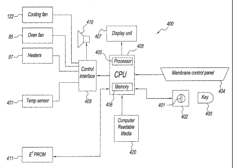
Referring to Fig. 5, a controller 400 is shown for oven 30. Controller
400 is similar to the controller shown in U.S. Patent Nos. 6,660,982 and
6,903,318. In particular, controller 400 includes a computer or central
processing unit (CPU) 408 that is interconnected with a key reader 402, a
manual control panel 404, a display unit 407, an audio alarm/beeper 410, a
control interface 409, a memory 411 and oven 30. CPU 408 comprises a
processor 405 and a memory 406.
Oven 30 comprises a temperature sensor 401 that is located in fan
box 72, preferably downstream of heater 87 and upstream of catalyst 98 or
catalyst 102 (Fig. 4). Temperature sensor 401 provides a signal that is
proportional to the temperature of fan box 72. This signal is coupled via
control interface 409 to CPU 408. Alternatively, temperature sensor 401
can be located in oven chamber 70.
CA 02772632 2012-02-29
WO 2011/028732
PCT/US2010/047389
Key reader 402 comprises a key aperture 401 adapted to receive a
data key 400. Data key 400 is provided with program data corresponding
to operation of oven 30. For example, data key 400 comprises a computer
readable media upon which are stored cooking procedures and/or program
code for operation of oven 30.
Key reader 402 comprises contacts that mate with contacts carried
on key 400 that allow data to be passed to and from data key 400. For
example, one or more programs for operating oven 30 may be stored on
data key 400 for access by processor 406 via key reader 402. Optionally,
processor 405 may store operating store in data key 400, which can be
used for service, maintenance, analysis and the like.
Control interface 409 is interconnected with a number of devices of
oven 30. To this end, control interface 409 is interconnected with cooling
fan 122, fan 85, heaters 87, temperature sensor 401 and an ambient
temperature sensor (not shown).
A memory 411 is connected with CPU 408 and may store one or
more programs used by CPU 408 for control of oven 30. Optionally,
memory 411 may be connected to control interface 409. In this case, CPU
408 accesses memory 411 via control interface 409. Memory 411, for
example, may be an EP2ROM.
A plurality of control programs is stored in memory 406, memory 411
and/or data key 400. These control programs include the energy saving
feature of the present invention, WHICH IS SHOWN IN Fig. 6 as energy
saving program 500.
Optionally, program data can be stored on any suitable computer
readable media 420 and accessed by CPU 408 via a USB port (not
shown). Computer readable media 420, for example, includes a data key
(such as data key 400), a computer disk, a flash memory, a SIM card, or
any other external computer readable memory media.
11
CA 02772632 2012-02-29
WO 2011/028732
PCT/US2010/047389
Referring to Fig. 6, energy saving program 500 causes CPU 408 to
control fan 85 and heater 87 during a non-cooking time of oven 30 to
conserve energy, i.e., minimize energy consumption of oven 30. When
oven 30 is operating within its normal parameters, controller 400 operates
in a food cooking mode to maintain a temperature of the heated air flow to
oven chamber 70 to at least one set point temperature. Controller 400
uses the temperature signal to control operation of heater 87 and fan 85 to
maintain the temperature of the heated airflow at a first set temperature
during a cooking mode. For example, from a cold start, controller 400 turns
heater 87 and fan 85. When a current temperature of the heated airflow
sensed by temperature sensor 401 attains the set point temperature (first
set temperature) of the food cooking mode, controller 400 turns heater 87
off. When the current temperature falls a predetermined amount below the
set point temperature, controller 400 turns heater 87 on. When the heated
air flow again attains the set point temperature, controller 400 turns heater
87 off. This procedure reiterates during the food cooking mode.
If oven 30 is inactive (not cooking food, door open or other non-
cooking activity), energy is in effect being wasted. Controller 400
minimizes these energy losses by entering an energy saving mode in which
the heated air flow is brought to and maintained at a second set
temperature, which is less than the first set temperature, thereby reducing
energy consumed by heater 87.
In particular, CPU 408 runs an energy saving program 500. At box
502, CPU 408 begins execution of program 500. At box 504, a period of
inactivity passes, e.g., 30 minutes while oven chamber 70 is initially heated
up to the cooking mode set temperature. For example, an inactivity timer is
set to a predetermined time indicative of the time of inactivity before entry
into an Energy Saving Mode and begins a count down to zero. At box 506,
CPU 408 compares the current time of the inactivity timer to zero. If
greater than zero, control reverts to box 504 or waits until the current time
equal zero. Alternatively, the inactivity counter could start from any known
12
CA 02772632 2012-02-29
WO 2011/028732
PCT/US2010/047389
time and box 506 would monitor the current time for an elapsed time equal
to the pre-defined inactivity time.
Should controller 400 begin controlling oven chamber 70 for an oven
chamber operation (e.g., cooking, cleaning, maintenance, etc.) during the
predefined inactivity period, the inactivity timer is reset. The inactivity
timer
is restarted when controller 400 again controls the temperature of oven
chamber 70 to the set temperature. For example, this could occur when a
cooking operation has ended.
When the current time of the inactivity timer is equal to or is less
than zero, an oven off timer is initiated at box 508. That is, the oven off
timer counts a pre-defined Energy Save Mode time period. At box 510, an
energy saving set point temperature becomes active for use during the
Energy Save Mode. The energy saving set point temperature is a suitable
reduced temperature that allows for continued heating of the air flow, for
example, 50 F less than the normal set temperature of a cooking mode.
For this example , the set temperature is reduced by about 50 F from the
food cooking mode set temperature. This causes CPU 408 to control
heater 87 based on the temperature sensed by temperature sensor 401 to
reduce the temperature of the heated air flow by about 50 F. For
example, heater 87 is turned off at this point and remains off until the fan
box temperature attains the reduced fan box temperature. At this point
controller 400 controls heater 87 to maintain the reduced fan box
temperature.
At box 512, CPU 406 reduces the speed of fan 85 to an energy
saving speed, but continues to circulate the heated air at the reduced
speed. That is, a reduced volume of air per unit time is being circulated.
Importantly, fan 85 consumes less energy, thereby reducing energy
consumption by fan 85.
13
CA 02772632 2012-02-29
WO 2011/028732
PCT/US2010/047389
At box 514, a display back light of display unit 407 is dimmed to
reduce consumption of electrical energy during the Energy Save Mode. At
box 516 CPU 406 determines if the current temperature sensed by
temperature sensor 401 is within the Energy Save Mode limits. If not, CPU
repeats execution of boxes 510, 512, 514 and 516. If the current sensed
temperature is within the limits, at box 516 reduces the speed of cooling fan
122 to an Energy Save Mode speed, thereby reducing energy consumption
of cooling fan 122.
At box 520, CPU 406 determines if the oven off timer equals zero. If
not, at box 522 CPU 406 determines if the Energy Save Mode is required.
If not, at box 524 CPU 406 returns controller to normal operation for a
cooking mode (i.e., reverts to the normal running parameters and continues
operation) and exits program 500 at box 528. For example, the Energy
Save mode is not required if the operator has placed food in the oven and
operated panel 404 to cause oven 30 to cook the food.
If at box 522 it is determined that the Energy Save Mode is required,
processor 405 repeats execution of boxes 510, 512, 514, 516, 518, 520
and 522. At box 520, if the oven off timer equals zero, CPU 406 turns oven
off. That is, the count of the oven off timer has reached the end of the
pre-defined Energy Save Mode time period. Should oven 30 still be
inactive at the end of this period, CPU 406 turns oven 30 off.
25 The oven of the present invention has several advantages:
Controller 400 reduces convection air speed to reduce heat losses from
oven chamber 70, thereby reducing energy consumption. Controller 400
during the Energy Save Mode continues to heat the air so as to enable
oven chamber 70 to regain temperature quickly upon restart. Controller
30 400 reduces the speed of cooling fan 122 to further reduce energy
consumption. Controller 400 reduces electrical current to the display back
light to further reduce electrical energy usage.
14
CA 02772632 2015-07-08
The present invention having been thus described with particular
reference to the preferred forms thereof, it will be obvious that various
changes and modifications may be made therein without departing from the
scope of the present invention as defined in the appended claims.