Note: Descriptions are shown in the official language in which they were submitted.
CA 02772865 2012-03-30
FLOTATION FOR AGRICULTURAL IMPLEMENTS
This invention is in the field of agricultural implements and in particular
such implements
with increased flotation and resistance to sinking into soft soil.
BACKGROUND
A common problem that farmers can experience at seeding time is the inability
to seed
their crops because excessive soil moisture makes the fields unable to support
the seeding
equipment, typically due to excessive or untimely rainfall. Sometimes as well
heavy
snow cover produces a lot of moisture which must either run off the fields, be
absorbed
by the soil or evaporate. A late, cool spring can slow the soil drying process
considerably.
Unfortunately, for maximizing crop yields and crop quality and also minimizing
the
chances of crop damage or complete crop losses for spring seeded crops, it is
necessary
for fanners to seed their crops within the finite window of time indicated as
acceptable by
past experience.
Seeding too late, especially in northern agricultural areas, exposes the crop
to the risk of
frost before the crop matures. This risk is recognized in some crop insurance
regimes
where crops must be seeded before a specified date in order to qualify for
crop insurance.
As farm sizes, crop input costs, land costs, and the like increase, the
negative
consequences for failing to seed a crop increase as well.
Agricultural air seeders are typically used to place seed and fertilizer in
the soil to plant a
crop. Such air seeders typically include a frame mounted on wheels for
movement along
the ground, and furrow openers mounted to the frame and spaced evenly across
the width
of the frame so that furrows and thus seed rows are evenly spaced across the
field. The
frame includes a hitch extending forward from the front end thereof and the
drawbar of a
2
CA 02772865 2012-03-30
towing tractor is attached to the front end of the hitch by a pin, such that
the frame is
pivotally attached to the drawbar about a vertical pivot axis provided by the
pin.
To provide even emergence of the crop plants, and to maximize yields, it is
desirable to
place the seeds at a consistent depth beneath the soil surface. One common
design to
accomplish this is to provide front and rear wheels along corresponding front
and rear
edges of the frame, so that the front and rear edges are then at a distance
above the
ground that is substantially the same regardless of ups and downs in the field
terrain and
is thus kept level. The furrow openers are located between the front and rear
wheels.
In air seeders with furrow openers mounted directly to the drill frame, the
furrow openers
extend the same distance downward from the frame so that the depth to which
each
furrow opener penetrates the soil is substantially the same, and is controlled
by moving
the front and rear wheels up and down with respect to the frame.
In air seeders with independent ground following openers, each furrow opener
is
independently mounted on an arm with a ground following wheel, and a hydraulic
cylinder exerts a downward bias force between the frame and the arm that
pushes the
furrow opener into the soil, and forces the ground following wheel against the
soil behind
the furrow opener to pack the soil over the seed. The relative position of the
furrow
opener and ground following wheel is adjusted to substantially control the
penetration
depth. The hydraulic cylinders also raise the arms to transport and lower them
for field
work.
Such independent furrow openers have been found to perform better in soft, wet
soil
conditions than the frame mounted openers, as the ground following wheel
prevents the
furrow opener from sinking further into the soil if the frame wheels sink in
the soft soil.
Seeding depth is thus better controlled, and the downward bias force exerted
on the arm
can be reduced where the soil is very soft. The weight of the implement is
also partially
3
CA 02772865 2012-03-30
carried on the ground following wheels, thus somewhat reducing the weight on
the front
and rear frame wheels, and reducing the tendency for the front and rear fame
wheels to
sink into soft soil.
The rear wheels are typically fixed to the frame such that the rotational axes
thereof are
perpendicular to the operating travel direction. Typically as well, the front
wheels are
caster wheels that can pivot freely about a vertical caster axis. The fixed
rear wheels
keep the implement moving in a straight line following the tractor, while the
castering
front wheels allow the implement to turn since the rolling orientation of the
caster wheels
changes to follow the frame as it moves in a lateral direction during the
turn.
A "floating" type hitch is pivotally attached to the frame about a hitch pivot
axis oriented
horizontally and perpendicular to the operating travel direction. The front
end of the
hitch connects to the tractor drawbar, and the floating hitch pivots up and
down with the
tractor drawbar and the frame as the tractor and implement move across a field
and as
terrain varies. This same arrangement is used on agricultural implements such
as
cultivators and the like, in addition to air seeders. The frame of a modern
agricultural
implement can be 80 feet or more wide, and so the frame is divided into side
by side
wing sections that pivot with respect to each other about frame pivot axes
oriented
parallel to the operating travel direction.
The front and rear frame wheels must support the weight of the implements, and
in
addition, ground engaging tools are often configured to draw them selves into
the ground,
thereby exerting additional downward forces that must be carried by the
wheels.
Compounding this problem is the fact that on floating hitch implements, the
tractor
drawbar is often lower than the hitch pivot axis, which results in an
additional downward
force component on the front of the frame, especially on the center section
where the
hitch is attached. Thus in soft soil conditions, the wheels, and the front
wheels in
particular, sink into the soil such that rolling resistance and draft forces
increase
4
CA 02772865 2012-03-30
significantly. Especially with frame mounted opener air seeders and
cultivators without
independent ground engaging tools, the depth of penetration of the ground
engaging tools
increases, which undesirably increases seed depth placement in an air seeder,
and also
further increases draft in all implements. When the soil is very soft as in
wet weather, the
implement can become stuck, and it is not then possible to carry on the
seeding operation.
Significant problems with wet conditions at seeding time were encountered for
example
in large areas of western Canada during the spring of both 2010 and 2011, with
many
fields going unseeded because the window of suitable time closed before the
fields were
dry enough for the fanners to operate their seeding equipment.
Considerable advice was circulated with respect to working wet fields with air
seeders,
such as reducing down pressure on furrow openers, changing packer wheels,
altering
travel paths, and the like. It was generally accepted that air seeders with
independent
ground following openers worked better, but in many areas the soil was too wet
for these
air seeders. Many fanners seeded by simply broadcasting seed on the soil,
often from
airplanes.
Significant effort was devoted to providing increased flotation for air
seeders in an
attempt to keep them operative in very wet field conditions. Some offered
larger front
caster wheel tires in an attempt to provide increased flotation, however it is
not possible
to significantly increase the diameter of the tires. Some farmers fitted track
assemblies in
place of the front caster wheels. Seed MasterTM of Regina, Canada recommended
an
optional lift kit for their air seeders to reduce the problem of getting
stuck. The lift kit
reduced the weight on the front caster wheels by transferring weight from the
front caster
wheels to the tractor drawbar and to the rear wheels through an arrangement
described in
Canadian Patent Application Number 2,645,522.
5
CA 02772865 2012-03-30
Increasing the diameter of a wheel generally provides a greater improvement in
flotation
and reduced rolling resistance compared to increasing the wheel width, and so
it is
desirable to provide larger diameter wheels. The diameter of the fixed rear
wheels may
be increased significantly to provide an increased support area of contact
with the ground,
however increasing the diameter of the castering front wheels that are
pivotally attached
to the frame through caster pivots is problematic for a number of reasons.
The hitch to tow the implement is attached to the center section, and the
front wheels
supporting the center section must be mounted on either side of the hitch. In
order to use
a large diameter castering flotation tire on the front of this center section
the castering
wheels would need to be moved away from the hitch such that there is
sufficient distance
on each side to provide a clear pivot envelope for the large diameter wheel to
pivot
between the caster axis and the hitch as it pivots through 360 degrees. In
some
implements it is known to support the front of the center section with a
single caster
wheel assembly in the middle of the center section, instead of mounting one on
each side,
however with larger implements with wing sections extending from each side of
the
center section, this arrangement lacks stability, especially when in
transport.
If the size of the front caster wheel is increased significantly, such as to
twice the
diameter for example, the caster bracket will need to be significantly larger,
stronger, and
more costly. The distance between the caster axis and the wheel/ground contact
surface
increases proportionally, and the 360 degree envelope becomes problematic.
Moving
these center section front caster wheels wide enough apart to provide this
clear envelope
results in an excessive distance between the wheels, such that travel on roads
during
transport is difficult, if not impossible. The wider spacing also adversely
affects ground
contour following characteristics of the implement.
Such agricultural implements typically make a sharp turn at the end of a field
pass, and
the caster wheels twist against the ground as the caster axis moves sharply
with the
6
CA 02772865 2012-03-30
implement frame causing soil disturbance. The twisting of a larger tire
against the
ground surface will exert increased forces on the caster bracket, and also
create a larger
soil disturbance. Such soil disturbance is particularly undesirable in modern
no-till
farming practices because conventional tillage is not carried out on the field
surface, and
so any ruts and disturbance made by an implement are not smoothed out by
normal
cultivation.
Thus increasing the diameter of the front wheels of agricultural implements
would be
highly beneficial by providing increased flotation, however the diameter is
constrained by
the need to allow the front caster wheels to pivot to vary the rolling
orientation thereof
and allow the front end of the implement to move laterally during turns.
SUMMARY OF THE INVENTION
It is an object of the present invention to provide an agricultural implement
apparatus
with increased flotation that overcomes problems in the prior art.
The increased flotation allows an air seeder of the present invention to
operate in soft soil
conditions where prior art air seeders would sink into the soil and become
stuck. The
number of days in a farmer's acceptable window of time for seeding where the
seeder can
be operated in wet soil conditions is increased, thus providing significant
financial
benefits in wet years when seeding of the crop in the limited window is not
otherwise
possible.
To allow the diameter of the front wheels to be increased in the present
invention, the
orientation of the front wheels that were formerly allowed to caster is
controlled so that
the size of the clear envelope required for movement of the front wheels is
reduced. The
pivoting range of the front wheels could be limited to something less than 360
degrees by
providing stops to restrict the rolling orientation of the castering wheels to
a lesser angle,
7
CA 02772865 2012-03-30
such as that required to turn a corner, however it would not then be possible
to move the
implement in reverse.
In a caster type wheel, the vertical caster axis is ahead of the rotational
axis of the wheel
in the direction of travel, and ahead of the contact surface between the wheel
and the
ground that is directly under the rotational axis such that the caster axis
and contact
surface are substantially aligned in the direction of movement with the wheel
trailing
behind the caster axis. The wheel pivots freely about the caster axis and will
pivot about
the caster axis to assume this relationship.
During a turn, the caster bracket attached to the implement frame that defines
the vertical
caster axis moves laterally and the caster wheel assembly pivots about the
vertical caster
axis to maintain the alignment in the new travel direction, and the rolling
orientation of
the wheel changes to follow the implement frame. When the implement moves in
reverse, as the caster bracket starts to move rearward, the wheel may
initially roll
rearward ahead of the caster axis, but as soon as the ground contact surface
and caster
axis are no longer exactly aligned in the travel direction, the caster wheel
will pivot about
180 degrees in one direction or the other so the wheel is trailing behind the
caster axis.
Because the wheel must pivot in either direction, an open pivot envelope must
be
provided that allows the caster wheel to pivot through 360 degrees.
In the present invention then the size of the clear envelope is reduced by
controlling the
rolling orientation of the front wheels instead of allowing the wheels to
pivot freely
through 360 degrees as in the prior art. Thus the size of the clear pivot
envelope that
must be provided to allow the front wheels to pivot through the required
operational
range is much reduced, and the large flotation front wheels can be located
close to the
hitch.
8
CA 02772865 2012-03-30
In a first embodiment the present invention provides an agricultural implement
apparatus
comprising a frame supported on rear wheels and at least one front flotation
wheel for
movement along the ground in an operating travel direction, and a plurality of
ground
engaging tools mounted on the frame substantially equally on each side of a
frame axis
extending parallel to the operating travel direction. The at least one front
flotation wheel
is pivotally mounted to the frame about a substantially vertical wheel pivot
axis. A hitch
tongue has a rear end pivotally attached to a lateral mid-point of the frame
about a
substantially vertical hitch pivot axis located substantially on the frame
axis, and a front
end adapted for pivotal attachment to a drawbar of a towing vehicle by a
substantially
vertical drawbar pin. A wheel control mechanism connects the at least one
front flotation
wheel to the hitch tongue such that pivotal movement of the at least one front
flotation
wheel about the wheel pivot axis follows pivotal movement of the hitch tongue
about the
hitch pivot axis. The wheel control mechanism is configured such that when the
hitch
tongue is in a neutral position aligned with the frame axis, the at least one
front flotation
wheel is oriented to roll in the operating travel direction, and pivoting the
hitch tongue
about the hitch pivot axis away from the neutral position causes the at least
one front
flotation wheel to pivot about the wheel pivot axis.
In a second embodiment the present invention provides a method of controlling
the
rolling orientation of at least one front flotation wheel of an agricultural
implement. The
method comprises supporting a frame on rear wheels and the at least one front
flotation
wheel for movement along the ground in an operating travel direction, and
mounting a
plurality of ground engaging tools on the frame substantially equally on each
side of a
frame axis extending parallel to the operating travel direction; pivotally
mounting the at
least one front flotation wheel to the frame about a substantially vertical
wheel pivot axis;
pivotally attaching a hitch tongue at a rear end thereof to a lateral mid-
point of a width of
the frame about a substantially vertical hitch pivot axis located
substantially on the frame
axis, and pivotally attaching a front end of the hitch tongue to a tow vehicle
drawbar with
a substantially vertical drawbar pin; connecting the at least one front wheel
to the hitch
9
CA 02772865 2012-03-30
tongue with a wheel control mechanism configured such that when the hitch
tongue is in
a neutral position the at least one front wheel is oriented to roll in the
operating travel
direction, and such that pivotal movement of the at least one front wheel
about the wheel
pivot axis follows pivotal movement of the hitch tongue about the hitch pivot
axis; and
operating the tow vehicle to tow the frame along a field surface with the
ground engaging
tools penetrating the field surface.
The invention thus addresses the problem of mounting large diameter flotation
wheels on
the front of the implement by providing a control mechanism for the rolling
orientation of
at least the center front wheels located on either side of the hitch. These
large diameter
wheels can thus be mounted about as close to the hitch as the prior art
castering front
wheels, such that road travel and contour following characteristics are not
adversely
affected. In addition to allowing for larger tires, the control apparatus
improves
perforinance on turns in the field, reducing soil disturbance as compared to
freely
castering wheels when in the field, and improves maneuverability when in
transport. In
another embodiment, a pivot restraint mechanism can also be operative to
selectively
secure the hitch tongue in the neutral position to reduce skewing tendencies
when in field
operation.
Additionally, the large diameter of the tire allows the tire to roll over soil
that is often
loosened and piled up by the spinning action of tractor tires. The situation
that is created
by the spinning action of the tractor tires can cause smaller diameter tires
to stop turning,
begin skidding and begin piling up soil ahead of the tire, which greatly
increases the force
required to tow the drill. This in turn increases the spinning action of the
tractor tires as
they attempt to apply more force to overcome the increasing resistance, and
eventually
the seeding implement can become stuck. The spinning action of the tractor
tires also
typically causes the tires on the air seeder that follow the tractor tires to
drop relative to
the nominal soil surface. When the depth of the seeding opener is partially
controlled by
the front wheel on the drill frame, the seeding depth is also adversely
affected and the
CA 02772865 2012-03-30
draft required to tow the seeding implement is increased thereby increasing
the spinning
action of the tires which further drops the depth of the seeding openers until
the seeding
unit become stuck. At times, the combination of the caster wheels skidding and
piling up
wet soil and the seeding openers dropping causes the seeding implement and
tractor to
become stuck.
DESCRIPTION OF THE DRAWINGS
While the invention is claimed in the concluding portions hereof, preferred
embodiments
are provided in the accompanying detailed description which may be best
understood in
conjunction with the accompanying diagrams where like parts in each of the
several
diagrams are labeled with like numbers, and where:
Fig. 1 is a schematic top view of an embodiment of an agricultural implement
apparatus of the present invention where the front flotation wheels are
castering wheels
and the wheel control mechanism is provided by control arms;
Fig. 2 is a schematic top view of an alternate embodiment of an agricultural
implement
apparatus of the present invention where the front flotation wheels are
mounted about a
vertical wheel pivot axis located directly above the rotational axes of the
front flotation
wheels, and where the wheel control mechanism is provided by control arms;
Fig. 3 is a schematic top view of an alternate embodiment of an agricultural
implement
apparatus of the present invention where the front flotation wheels are
mounted about a
vertical wheel pivot axis located directly above the rotational axes of the
front flotation
wheels, and where the wheel control mechanism is provided by connected
hydraulic
cylinders;
11
CA 02772865 2012-03-30
Fig. 4 is a schematic top view of the embodiment of Fig. 3 with the hitch
tongue in a
leftward turning position, and the front flotation wheels turned to the left;
Fig. 5 is a schematic perspective view of an embodiment of an agricultural
implement
apparatus of the present invention;
Fig. 6 is a top view of the embodiment of Fig. 5 with the hitch tongue in a
leftward
turning position;
Fig. 7 is a top view of the embodiment of Fig. 5 with the hitch tongue in the
neutral
position and with a pivot restraint mechanism installed and in the release
position;
Fig. 8 is a top view of the embodiment of Fig. 7 with the hitch tongue in the
neutral
position and with the pivot restraint mechanism in the restraint position;
Fig. 9 is a top view of the embodiment of Fig. 7 with the hitch tongue in a
leftward
turning position and with the pivot restraint mechanism in the release
position;
Fig. 10 is a top view of the embodiment of Fig. 5 with the outboard castering
front
wheels replaced by much larger outboard front wheels with a controlled rolling
orientation;
Fig. 11 is a top view of the embodiment of Fig. 10 with the hitch tongue in a
leftward
turning position, and the flotation front wheels and controlled flotation
outboard front
wheels oriented to roll to the left;
Fig. 12 is a top view of the embodiment of Fig. 10 with a pivot restraint
mechanism
installed and in the release position and with the hitch tongue in the neutral
position
12
CA 02772865 2012-03-30
and the controlled flotation front wheels and controlled flotation outboard
front wheels
oriented to roll in the operating travel direction;
Fig. 13 is a top view of the embodiment of Fig. 10 with the pivot restraint
mechanism
in the restraint position with the hitch tongue in the neutral position;
Fig. 14 is a top view of the embodiment of Fig. 10 with the pivot restraint
mechanism
in the release position and with the hitch tongue in a leftward turning
position and the
controlled flotation front wheels and controlled flotation outboard front
wheels
oriented to roll to the left;
Fig. 15 schematically illustrates skewing of the implement frame about the
hitch pivot
axis;
Fig. 16 schematically illustrates skewing of the implement frame about the
drawbar
pivot axis;
Fig. 17 schematically illustrates a basic embodiment of a pivot restraint
mechanism
that is provided by a lock pin movable from a locked position, engaging the
hitch
tongue and the frame in the neutral position, to an unlocked position
releasing the hitch
tongue to pivot freely.
DETAILED DESCRIPTION OF THE ILLUSTRATED EMBODIMENTS
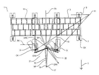
Fig. 1 schematically illustrates an embodiment of a agricultural implement
apparatus 1 of
the present invention. The apparatus 1 comprises a frame 3 supported for
movement
along the ground in an operating travel direction T on rear wheels 5, right
and left
outboard castering front wheels 7, and right and left controlled flotation
front wheels 9.
A plurality of ground engaging tools 11, for example the furrow openers of an
air seeder
13
CA 02772865 2012-03-30
or cultivator shanks, are mounted on the frame 3 substantially equally on each
side of a
frame axis FA extending parallel to the operating travel direction. The rear
wheels 5 are
fixed to the frame such that rotational axes thereof are perpendicular to the
operating
travel direction T. The right and left outboard castering front wheels 7 pivot
freely about
substantially vertical caster axes CA.
Front flotation wheels 9 are illustrated as the conventional castering type
wheels pivotally
mounted to the frame 3 on wheel arms 13 about substantially vertical wheel
pivot axes
provided by caster axes CA' located forward of the rotational axes RA of the
flotation
wheels 9, however the front flotation wheels 9 have a diameter that is about
twice the
diameter of the rear wheels 5 and outboard castering front wheels 7 and are
much wider
as well. The smaller wheels 5 and 7 are shown as dual wheel assemblies, with
two side
by side wheels instead of the single large diameter front flotation wheel 9,
however the
larger single wheel does provide increased floatation compared to the smaller
diameter
dual wheels.
A hitch tongue 15 has a rear end pivotally attached to a lateral mid-point of
the frame,
located substantially on the frame axis FA, about a substantially vertical
hitch pivot axis
HPA, and has a front end adapted for pivotal attachment to the drawbar 17 of a
tractor or
like towing vehicle by a substantially vertical drawbar pin 19 which provides
a
substantially vertical drawbar pivot axis DPA.
A wheel control mechanism 21 connects the front flotation wheels 9 to the
hitch tongue
15 such that pivotal movement of the front flotation wheels 9 about the caster
axes CA'
follows pivotal movement of the hitch tongue 15 about the hitch pivot axis
HPA. The
wheel control mechanism 21 is configured such that when the hitch tongue 15 is
in a
neutral position NP aligned with the frame axis FA, the front flotation wheels
9 are
oriented to roll in the operating travel direction T, and pivoting the hitch
tongue 15 about
the hitch pivot axis HPA away from the neutral position NP causes the front
flotation
14
CA 02772865 2012-03-30
wheels 9 to pivot about the caster axes CA', as schematically illustrated in
Fig. 1 where
moving the hitch 15 to the left, as in making a left turn, turns the rolling
orientation of the
front flotation wheels 9 to the left to follow the left turn.
In the embodiment of Fig. 1, the wheel control mechanism 21 is provided by
right and
left control arms 22 connect corresponding right and left flotation front
wheels 9 to the
hitch tongue 15 at a control axis CTA forward of the hitch pivot axis HPA. The
right and
left control arms 22 are configured such that pivoting the hitch tongue 15
about the hitch
pivot axis HPA away from the neutral position NP causes the right and left
flotation front
wheels 9 to pivot about the corresponding caster axes CA' such that front
edges of the
right and left flotation front wheels 9 move in the same direction as the
hitch tongue 15,
substantially as illustrated in Fig. 2. When the hitch tongue 15 is in the
neutral position
NP the right and left front flotation wheels 9 are oriented to roll in the
operating travel
direction T.
Thus the rolling orientation of the front flotation wheels 9 is controlled by
the position of
the hitch tongue 15. When the hitch tongue 15 moves laterally during a turn,
the front
flotation wheels 9 turn in the same direction.
It can be seen in Fig. 1 that when the castering front flotation wheels 9
pivot about the
caster axes CA', the clear envelope required for movement of the front
flotation wheels 9
about the caster axes CA' must be large enough to accommodate the distance
from the
caster axis CA' to the rear edge of the wheel 9. The wheel 9 is offset
rearward from the
caster axis CA' and so the entire width of the wheel 9 must move toward the
forward
extending hitch section 311 of the frame 3.
Fig. 2 therefore schematically shows a more advantageous embodiment of an
agricultural
implement apparatus 1' of the present invention where the front flotation
wheels 9' are
pivotally mounted to the frame 3 about substantially vertical wheel pivot axes
WPA
CA 02772865 2012-03-30
located directly above the rotational axes RA of the flotation wheels 9'.
Since pivotal
movement of the front flotation wheels 9' is controlled in the present
invention, the
castering configuration is not required. The wheel control mechanism 21 is
again
provided by right and left control arms 22 substantially the same as in Fig. 1
that connect
Thus in the apparatus 1' of Fig. 2, when the front flotation wheels 9' pivot
about the
wheel pivot axes WPA, the clear envelope required for pivotal movement of the
front
Figs. 3 and 4 schematically illustrate a further alternate agricultural
implement apparatus
1" where the front flotation wheels 9" are mounted on wheel pivot axes WPA"
above the
16
CA 02772865 2012-03-30
In the apparatus 1" illustrated in Fig. 3 the hitch tongue 15" extends
rearward of the hitch
pivot axis HPA and the first hydraulic cylinder 24A of the left pair of
control hydraulic
cylinders 24 is connected to the hitch tongue 15" rearward of the hitch pivot
axis HPA
and on the side of the hitch tongue 15" opposite the left front flotation
wheels 9L". Thus
when the hitch tongue 15" moves to the left, the first hydraulic cylinder 24A
extends and
hydraulic fluid is pushed into the second hydraulic cylinder 24B which
retracts and turns
the left front flotation wheel 9L" to the left, as illustrated in Fig. 4
In the same manner a right pair of control hydraulic cylinders 25 comprises a
first
hydraulic cylinder 25A connected to the hitch tongue 15" rearward of the hitch
pivot axis
HPA and to the frame 3, and a second hydraulic cylinder 25B connected to the
frame 3
and to the right front flotation wheel 9R". Chambers of the first and second
hydraulic
cylinders 25A, 25B are connected such that movement of the hitch tongue 15"
away from
the neutral position NP moves hydraulic fluid from the first hydraulic
cylinder 25A into
the second hydraulic cylinder 25B to pivot the right front flotation wheel 9R"
in the
direction moved by the hitch tongue 15.
Figs. 5 - 9 schematically illustrate an alternate embodiment of an
agricultural implement
apparatus 101 of the present invention. The apparatus 101 comprises a frame
103
supported for movement along the ground in an operating travel direction T on
rear
wheels 105, right and left outboard castering front wheels 107, and right and
left
controlled flotation front wheels 109. A plurality of ground engaging tools
111, for
example the furrow openers of an air seeder or cultivator shanks, are mounted
on the
frame 103 substantially equally on each side of a frame axis FA extending
parallel to the
operating travel direction. The rear wheels 105 are fixed to the frame such
that rotational
axes thereof are perpendicular to the operating travel direction T. The right
and left
outboard castering front wheels 107 pivot freely about substantially vertical
caster axes
CA.
17
CA 02772865 2012-03-30
The frame 103 comprises a forward extending hitch section 103H and an axle
member
113 is mounted at a front end of the hitch section 103H substantially
perpendicular to the
operating travel direction T and in a center of a width of the frame 103. It
is
contemplated that in large implements, the axle member 113 will be fixed with
respect to
the frame, and essentially form part of the frame. The right and left
flotation front wheels
109 are pivotally mounted to the frame 103 by mounting same on corresponding
right
and left ends of the axle member 113 about substantially vertical right and
left wheel
pivot axes WPA. The axle member 113 is substantially aligned with rotational
axes of
the right and left flotation front wheels 109 when the flotation front wheels
109 are
rolling in the operating travel direction T.
It can be seen that the flotation front wheels 109 have a much larger diameter
as well as
width than the outboard castering front wheels 107 and thus provide
significantly
improved flotation for the center front portion of the frame 103. It is
contemplated that
the front flotation wheels will have a diameter of greater than about four
feet,
substantially larger than conventional castering front wheels which are
typically up to
about 40 inches in diameter, and in this description the term "flotation
wheel" generally
refers to a wheel much larger than conventional implement wheels, and in
particular to
wheels with a diameter greater than about four feet.
A hitch tongue 115 has a rear end pivotally attached to a lateral mid-point of
the frame
about a substantially vertical hitch pivot axis HPA, and has a front end
adapted for
pivotal attachment to the drawbar 117 of a tractor or like towing vehicle by a
substantially vertical drawbar pin 119 which provides a substantially vertical
drawbar
pivot axis DPA.
The wheel control mechanism 123 is provided by right and left control arms 122
connecting corresponding right and left flotation front wheels 109 to the
hitch tongue 115
18
CA 02772865 2012-03-30
at a control axis CTA forward of the hitch pivot axis HPA. The right and left
control
arms 22 are configured such that pivoting the hitch tongue 115 about the hitch
pivot axis
HPA away from the neutral position NP shown in Fig. 7, aligned with the frame
axis FA,
causes the right and left flotation front wheels 109 to pivot about the
corresponding right
and left wheel pivot axes WPA such that front edges of the right and left
flotation front
wheels 109 move in the same direction as the hitch tongue 115, substantially
as
illustrated in Fig. 6. When the hitch tongue 115 is in the neutral position NP
the right and
left front flotation wheels 109 are oriented to roll in the operating travel
direction T.
Thus the rolling orientation of the front flotation wheels 109 is controlled
by the position
of the hitch tongue 115. When the hitch tongue 115 moves laterally during a
turn, the
front flotation wheels 109 follow and turn in the same direction.
To allow the hitch tongue 115 to float to follow the ground, the hitch tongue
115 will
typically comprise a rear tongue section 115R pivotally attached to the frame
about the
substantially vertical hitch pivot axis HPA and a front tongue section 115F
pivotally
attached to the rear tongue 115R section about a substantially horizontal
tongue section
axis TA, as illustrated in Fig. 7. For clarity of illustration of the
principles of operation of
the invention these features are not shown on the other drawings.
The frame103 and hitch tongue 115 are configured such that when the hitch
tongue 115 is
in a neutral position NP with respect to the hitch pivot axis, as illustrated
in Figs. 7 and 8,
the hitch tongue 115 is in a desired operating orientation with respect to the
frame 103,
aligned with the frame axis as shown in Fig. 7.
Especially in minimum tillage agricultural operations that are popular today,
there is
considerable plant residue left on field soil surfaces where agricultural
implements are
used. Soil and plant residue are disturbed by the ground engaging tools, and
must flow
around the tool as it moves through the soil. To provide room for soil and
residue to flow
19
CA 02772865 2012-03-30
around the ground engaging tools, the tools are mounted to the frame in a
number of
generally parallel rows that are spaced apart from the front of the frame to
the rear of the
frame. The frame 103 of the illustrated apparatus 101 therefore comprises
parallel
members 103P spaced from the front to the rear of the frame, and the ground
engaging
tools 111 are spaced along the parallel members 103P, with equal numbers on
each side
of the frame axis FA. Thus the ground engaging tools 111 on each row are
separated by
a distance equal to three times the row spacing, providing ample room for soil
and plant
residue to flow between the tools 111 on each row.
When the frame 103, and thus parallel members 103P, are oriented perpendicular
to the
operating travel direction T, the ground engaging tools 111 engage the ground
at
substantially equally spaced furrows 111F. This then is the desired
orientation of the
frame 103, and when the hitch tongue 115 is in the neutral position, it
extends forward
from the hitch pivot axis HPA in the center of the width of the frame 103 at
the frame
axis FA, parallel to the operating travel direction T and aligned with the
frame axis FA,
and perpendicular to the parallel members 103P of the frame.
During operation, due to soil conditions, slopes, and the like, one side of
the frame 103 is
often subjected to drag forces that are greater or less than those on the
other side so that
one side drags back and the frame 103 pivots about the drawbar pin axis DPA
and moves
along the field at some angle that is not perpendicular to the operating
travel direction T.
This is commonly called a skewed orientation and is undesirable since as the
frame 103
skews, the furrows in the soil move from an equal spacing to an unequal
spacing.
Where considerable weight is carried on the implement frame, such as in some
air
seeders where agricultural products are carried on the frame, skewing is not
such a
significant problem, as the weight on the wheels increases the drag force
required to
cause the frame to skew. In other common air seeders where the agricultural
products are
carried on a separate cart, skewing can be more problematic. In such air
seeders, to
CA 02772865 2012-03-30
reduce skewing a pivot restraint mechanism 126 can be provided that is
selectively
operative to secure the hitch tongue 115 in the neutral position NP as
illustrated in Figs. 7
- 8.
The desired equally spaced furrows 111F are provided when the frame 103 is
perpendicular to the operating travel direction T. Unequal forces on the right
and left
sides of the frame 103 result in a net force K, as shown in Figs. 15 and 16,
which will
cause the frame 103 to skew, where one side of the frame moves backward and
the other
side moves forward. In a conventional hitch assembly, the hitch tongue is
fixed
perpendicular to the frame and the frame thus pivots about the drawbar pivot
axis at the
front of the hitch tongue.
However in order to provide control of the rolling orientation of the front
wheels, the
hitch tongue 115 of the present apparatus 101 must be able pivot at the hitch
pivot axis
HPA much closer to the frame. In that case when the frame 103 skews or pivots
in
response to unequal forces, the front end of the frame 103 will move through
an arc AF
with a center at the hitch pivot axis HPA, and the rear end of the frame 103
will move
through an arc AR with a center at the hitch pivot axis HPA, as schematically
illustrated
in Fig. 15. It can be seen that, for any given degree of skew, ground engaging
tools along
the rear of the frame 103 will move laterally much farther than those on the
front end of
the frame 103, and the furrow spacing will be impaired with only a relatively
small
degree of skewing. It is generally accepted that maximum crop yields are
attained when
plants are evenly spread across the field, so the unequal spacing of furrow
openers on air
seeders caused by implement skewing is undesirable.
With the pivot restraint mechanism 126 securing the hitch tongue 115 in the
neutral
position, the frame 103 will pivot about the vertical drawbar pivot axis DPA
at the front
of the hitch tongue 115, as schematically illustrated in Fig. 16. Then when
the frame 103
skews in response to unequal forces, the front end of the frame 103 will move
through an
21
CA 02772865 2012-03-30
arc AF' with a center at the drawbar pivot axis DPA, and the rear end of the
frame 103
will move through an arc AR' with a center at the drawbar pivot axis DPA.
Relative
lateral movement of the ground engaging tools on the front and rear ends of
the frame
103 is much reduced, and impairment of the furrow spacing is reduced. Thus the
pivot
restraint mechanism 126 can be operated to engage the hitch tongue 115 and
when the
implement apparatus 101 is moving generally straight in the operating travel
direction T,
and then to disengage the hitch tongue 115 and allow same to pivot about the
hitch pivot
axis HPA when it is desired to turn the front flotation wheels 109, such as
during a
sharper turn.
In a very basic embodiment, such as is schematically illustrated in Fig. 17, a
pivot
restraint mechanism 126' could be provided by a lock pin 127 movable from a
locked
position LP, illustrated in phantom lines, engaging the hitch tongue 115' and
the frame
103' through holes in each and thus securing the hitch tongue 115' in the
neutral position,
to an unlocked position ULP where the lock pin 127 is disengaged from the
holes in the
hitch tongue 115' and the frame 103', and a control 128 selectively operative
to activate
pin actuators 129 to move the pin 127 to one of the locked position LP and the
unlocked
position ULP.
More conveniently, the pivot restraint mechanism 126 illustrated in Figs. 7 ¨9
comprises
right and left extendable actuators 131 connected between the frame 103 and
hitch tongue
115.
The right extendable actuator 131R is movable from a restraint position
illustrated in Fig.
8, resisting rightward pivotal movement of the hitch tongue 115 away from the
neutral
position NP, to a release position illustrated in Fig. 7 where the hitch
tongue 115 is free to
move rightward away from the neutral position NP. Similarly the left
extendable actuator
131L is movable from a restraint position illustrated in Fig. 8, resisting
leftward pivotal
movement of the hitch tongue 15 away from the neutral position NP, to a
release position
22
CA 02772865 2012-03-30
illustrated in Fig. 7 where the hitch tongue 115 is free to move leftward away
from the
neutral position 15.
The extendable actuators 131 are provided in the illustrated apparatus 101 by
right and
left hydraulic cylinders 131R, 131L. The right and left hydraulic cylinders
131R, 131L
are configured to be fully extended when in the restraint position of Fig. 8
with the hitch
tongue 115 in the neutral position, and are operated as bias elements
operative to exert a
bias force BF resisting movement of the hitch tongue 115 away from the neutral
position
NP. An active hydraulic source 133 is connected to the right and left
hydraulic cylinders
131R, 131L through a hydraulic control 135 as schematically illustrated in
Fig. 8 only.
The hydraulic control 135 is operative to move the hydraulic cylinders between
the
restraint position of Fig. 8 and the release position of Fig. 7. Being fully
extended in the
restraint position, the hydraulic cylinders 131 in that position do not exert
any force
against the hitch tongue, but movement away from the neutral position tends to
cause one
of the hydraulic cylinders to retract and the bias force BF is then exerted to
resist
retraction. It is also contemplated that hydraulic cylinders could instead be
configured to
be fully retracted when in the restraint position and exert the bias force
when a force is
exerted to extend the hydraulic cylinders.
When the hydraulic cylinders 131 are in the restraint position, pressurized
hydraulic fluid
at an active pressure from the active hydraulic source 133 is directed into
the hydraulic
cylinders 131 to exert the bias force BF, and the active hydraulic source 133
is operative
to allow pressurized hydraulic fluid to pass out of the hydraulic cylinders
131 when a
hitch force HF exerted on the hitch tongue 115 in a direction away from the
neutral
position NP exceeds the bias force BF, such that the hitch tongue 115 moves
away from
the neutral position NP against the bias force BF.
By this arrangement, movement of the hitch tongue 115 and thus pivoting of the
front
flotation wheels 109 is possible when the towing vehicle makes a turn that
exerts a
23
CA 02772865 2012-03-30
sufficiently large hitch force HF to overcome the bias force BF. It is
contemplated that
the uneven forces that cause skewing will pivot the hitch tongue 115 about the
drawbar
pivot axis DPA and will not generally be sufficiently large to overcome the
bias force BF
and move the hitch tongue 115 from the neutral position NP. Thus the desired
operation
with the hitch tongue 115 in the neutral position NP will be maintained until
the greater
hitch forces HF generated during a turn are encountered.
Ideally to maintain equal furrow spacing it is desirable to drive across a
field in straight
lines, making a 180 degree turn at each end. Field shapes however are not
always
amenable to travelling in a straight line and some curves and turns of greater
or lesser
degree are a common part of farm implement operations. The pressure control
135 is
also operative to adjust the active pressure to adjust the bias force BF to
allow movement
of the hitch tongue 115, and thus turning of the front flotation wheels 109,
at a selected
hitch force. Thus the bias force BF can be adjusted so that in a gentle turn,
the hitch
tongue is maintained in the neutral position NP, while in a sharper turn the
hitch tongue
115 can move away from the neutral position NP and turn the implement
apparatus 101.
In the pivot restraint mechanism 126 of the illustrated apparatus 101, each of
the right
and left hydraulic cylinders 131 is pivotally connected at a rear end thereof
to the forward
extending hitch section 103H of the frame 103 and at a front end thereof to a
first end
137A of a link member 137. The opposite second end 37B of the link member 137
is
pivotally connected to the hitch tongue 115. Moving the hydraulic cylinders
131 to the
restraint position by directing pressurized hydraulic fluid into the hydraulic
cylinders 131
such that the hydraulic cylinders 131 extend moves the first ends 137A of the
link
members 137 against the hitch tongue 115, as shown in Fig. 8, and shifts the
hitch tongue
115 to the neutral position NP. When the hydraulic cylinders 131 are fully
extended, the
first ends 137A of the link members 137 are positioned closely adjacent each
side of the
hitch tongue 115, and secure the hitch tonguel 15 in the neutral position.
24
CA 02772865 2012-03-30
Moving the hydraulic cylinders to the release position moves the first ends
137A of the
link members 137 away from the hitch tongue 115 as shown in Fig. 7. The
hydraulic
cylinders 131 are fully extended when in the restraint position and also fully
retracted
when in the release position of Fig. 7. The hydraulic cylinders 131 and link
members 137
are configured such that when the hydraulic cylinders 131 are in the release
position and
the hitch tongue pivots leftward to a selected maximum degree from the neutral
position
NP, as illustrated in Fig. 9, the first end 137A of the left link member 137L
connected to
the left hydraulic cylinder 131L bears against the hitch tongue 115 and
prevents pivotal
movement of the hitch tongue 115 beyond the selected maximum degree shown in
Fig. 9.
Rightward movement of the hitch tongue 115 is similarly limited.
The hydraulic control 135 acts as a pivot control selectively operative to
move the pivot
restraint mechanism 126 from a restraint mode, where the hitch tongue 115 is
secured in
the neutral position, to a release mode where the hitch tonguel 15 is free to
pivot about
the hitch pivot axis HPA. A tool control 139 is selectively operative to raise
and lower
the ground engaging tools 111 with respect to the frame 103. Conveniently the
hydraulic
pivot control 135 is operatively connected to the tool control 139 such that
when the
ground engaging tools 111 are raised, the hydraulic pivot control 135 moves
the pivot
restraint mechanism 126 to the release mode, and when the ground engaging
tools 111
are lowered, the hydraulic pivot control 135 moves the pivot restraint
mechanism 126 to
the restraint mode. When making straight passes back and forth across a field,
the
ground engaging tools 111 are typically raised at the end of each pass to
facilitate making
the 180 degree turn. With this arrangement, when the ground engaging tools are
raised,
the pivot restraint mechanism 126 automatically releases the hitch tongue to
pivot and
provide pivotal movement of the front flotation wheels 109.
The implement apparatus 1 will typically include a transport control 141
selectively
operative to move the frame 103 to a transport position by raising the wings
103W to an
upright position. It is contemplated that in most applications, when
travelling in the
CA 02772865 2012-03-30
transport position the pivot restraint mechanism 126 will be in the release
mode so that
the towing tractor can maintain steering control of a heavy implement. This is
also
desirable when making a sharp turn, such as from the road into a field
approach.
Figs. 10 ¨ 14 schematically illustrate a version of the implement apparatus
101' where
the outboard castering front wheels 107 of Figs. 1 ¨ 5 are replaced by right
and left
controlled outboard front wheels 143 of the same larger size as the central
front flotation
wheels 109 which provide significantly improved flotation for the outer front
portions of
the frame 103. The pivot restraint mechanism 126 as described above is added
to the
implement apparatus 101' in Figs. 12 - 14.
The controlled outboard front wheels 143 are mounted to the frame 103 about
substantially vertical wheel pivot axes WPA, and a control linkage connects
the right and
left controlled outboard front wheels 143 to the hitch tongue 115 such that
moving the
hitch tongue 115 away from the neutral position NP in a selected direction
turns the
controlled outboard front wheels 143 in the selected direction. In the
illustrated apparatus
101', the rotational axes RA of the front flotation wheels 109 and the
controlled outboard
front wheels 143 are substantially aligned when the wheels 109, 143 are
oriented to roll
in the operating travel direction T as shown in Fig. 10. Thus the central and
outer
portions of the front of the frame 103 are supported along the aligned
rotational axes RA,
and the separation distance between the outboard front wheels 143 and the rear
wheels
105 is increased somewhat to provide the larger diameter flotation wheels 143.
To provide a smooth turn, the control linkage is configured such that moving
the hitch
tongue 115 to a selected maximum degree from the neutral position, as
illustrated in Fig.
11, pivots the right and left controlled front flotation wheels 109 and the
right and left
controlled outboard front wheels 143 about their respective vertical wheel
pivot axes
WPA such that rotational axes RA of the right and left front flotation wheels
109 and the
right and left controlled outboard front wheels 143 intersect generally at a
desired turning
26
CA 02772865 2012-03-30
axis E. Figs. 7 and 9 show a similarly located turning axis E, where the
outboard front
wheels are castering wheels 107 pivoting about vertical caster axes CA.
In the illustrated apparatus 101', the control linkage for the controlled
outboard front
wheels 143 comprises a right pair of control hydraulic cylinders 145
comprising a first
hydraulic cylinder 145A connected to the hitch tongue 115 and to the frame 103
at the
forward extending hitch section 103H thereof, and a second hydraulic cylinder
145B
connected to the frame 103 and to the right controlled outboard front wheel
143R.
Chambers of the first and second hydraulic cylinders 145A, 145B are connected
or slaved
such that movement of the hitch tongue 115 away from the neutral position NP
of Fig. 10
toward the turned position of Fig. 11 moves hydraulic fluid from the first
hydraulic
cylinder 145A into the second hydraulic cylinder 145B to pivot the right
controlled
outboard front wheel 143R and pivot same in the direction moved by the hitch
tongue 15.
The hitch tongue 115 extends rearward of the hitch pivot axis HPA and the
first hydraulic
cylinder 145A of the right pair of control hydraulic cylinders 145 is
connected to the
hitch tongue 115 rearward of the hitch pivot axis HPA and on the side of the
hitch tongue
115 opposite the right controlled outboard front wheel 143R. Thus as can be
seen in
figures, when the hitch tongue moves to the left as in Fig. 11, the first
hydraulic cylinder
145A retracts and hydraulic fluid is pushed into the second hydraulic cylinder
145B
which extends and turns the right controlled outboard front wheel 143R to the
left.
In the same manner a left pair of control hydraulic cylinders 147 comprises a
first
hydraulic cylinder 147A connected to the hitch tongue 115 rearward of the
hitch pivot
axis HPA and to the frame 103, and a second hydraulic cylinder 147B connected
to the
frame 103 and to the left controlled outboard front wheel 143L, wherein
chambers of the
first and second hydraulic cylinders 147A, 147B are connected such that
movement of
the hitch tongue 115 away from the neutral position NP moves hydraulic fluid
from the
27
CA 02772865 2012-03-30
first hydraulic cylinder 147A into the second hydraulic cylinder 147B to turn
the left
controlled outboard front wheel 143L in the direction moved by the hitch
tongue 115.
The present invention thus provides controlled pivoting and turning of the
front wheels of
an agricultural implement that allows for the use of substantially larger
diameter front
wheels to increase flotation support and reduce the tendency of the front end
of such
implements to sink into soft soil, thus allowing the implement to operate on
soft soil
where the wheels of conventional implements would sink and the implement would
be
stuck and unable to work. Increased flotation also improves depth dontrol,
decreases
draft, and reduces ruts that adversely affect subsequent field operations such
as
harvesting. Controlled pivoting of the front wheels also reduces stresses on
the
implement during turns.
The present invention thus provides a method of controlling the rolling
orientation of at
least one front flotation wheels of an agricultural implement 1. The method
comprises
supporting a frame on front and rear wheels 5, 7, 9 for movement along the
ground in an
operating travel direction T. and mounting a plurality of ground engaging
tools 11 on the
frame 3; pivotally mounting front flotation wheels 9 to the frame 3 about
vertical wheel
pivot axes WP; pivotally attaching a hitch tongue 15 to a mid-point of a width
of the
frame 3 about a substantially vertical hitch pivot axis HPA, and pivotally
attaching a
front end of the hitch tongue 15 to a to tow vehicle drawbar 17 with a
substantially
vertical drawbar pin 19; connecting the front flotation wheels 9 to the hitch
tongue 15
with a wheel control mechanism comprising control arms 22 or control hydraulic
cylinders 24 configured such that when the hitch tongue 15 is in a neutral
position NP the
front flotation wheels 9 are oriented to roll in the operating travel
direction T; operating
the tow vehicle to tow the frame 3 along a field surface with the ground
engaging tools
11 penetrating the field surface.
28
CA 02772865 2012-03-30
The method can further comprise, as illustrated in Figs. 7 ¨ 9, operating the
tow vehicle
to tow the frame 103 along the field surface in a substantially straight line
with the hitch
tongue 115 secured in the neutral position NP about the hitch pivot axis HPA,
the neutral
position NP selected to place the hitch tongue 115 in a desired operating
orientation with
respect to the frame 103; and releasing the hitch tongue 15 from the neutral
position NP
and turning the tow vehicle such that the hitch tongue 115 pivots about the
hitch pivot
axis HPA and moves the wheel control mechanism 126 to pivot the front
flotation wheels
109 about the wheel pivot axes WPA and turn the frame 103 in the same
direction as the
tow vehicle.
The method can further comprise exerting a bias force BF on the hitch tongue
115
resisting movement of the hitch tongue 115 away from the neutral position NP,
the bias
force BF selected such that when operating the tow vehicle to tow the frame
103 in a
substantially straight line along a field surface with the ground engaging
tools 111
penetrating the field surface the hitch tongue 115 is secured in the neutral
position NP,
and when the tow vehicle is turned the hitch tongue 115 pivots about the hitch
pivot axis
HPA against the bias force BF. The bias force BF is exerted by a pivot
restraint
mechanism 126 when the pivot restraint mechanism 126 is in a restraint mode,
and no
bias force is exerted on the hitch tongue 115 when the pivot restraint
mechanism 126 is in
a release mode. The pivot restraint mechanism 126 is operated in the restraint
mode
when turns are in a first shallow range of turn degree, and the pivot
restraint mechanism
is operated in the release mode when turns are in a second sharp range of turn
degree.
The foregoing is considered as illustrative only of the principles of the
invention.
Further, since numerous changes and modifications will readily occur to those
skilled in
the art, it is not desired to limit the invention to the exact construction
and operation
shown and described, and accordingly, all such suitable changes or
modifications in
structure or operation which may be resorted to are intended to fall within
the scope of
the claimed invention.
29