Note: Descriptions are shown in the official language in which they were submitted.
CA 02773599 2012-03-08
WO 2011/034589 PCT/US2010/002523
1
TITLE
FORMATION OF LATEX COAGULUM COMPOSITE
BACKGROUND OF THE INVENTION
1. Field of the Invention.
[0001] This invention relates to the introduction of additional elastomer
latex into a
latex coagulum composite.
2. Description of the Related Art.
[0002] Numerous products of commercial significance are formed of elastomeric
compositions wherein particulate filler is dispersed in any of various
synthetic
elastomers, natural rubber or elastomer blends. Carbon black, for example, is
widely
used as a reinforcing agent in natural rubber and other elastomers. It is
common to
produce a masterbatch, that is, a premixture of filler, elastomer and various
optional
additives, such as extender oil. Carbon black masterbatch is prepared with
different
grades of commercially available carbon black which vary both in surface area
per unit
weight and in structure, which describes the size and complexity of aggregates
of
carbon black formed by the fusion of primary carbon black particles to one
another.
Numerous products of commercial significance are formed of such elastomeric
compositions of carbon black particulate filler dispersed in natural rubber.
Such
products include, for example, vehicle tires wherein different elastomeric
compositions
may be used for the tread portion, sidewalls, wire skim and carcass. Other
products
include, for example, engine mount bushings, conveyor belts, windshield wipers
and
the like.
[0003] There are a variety of methods for producing carbon black masterbatch.
In one
method, disclosed in U.S. Patent No. 6,841,606 ("the '606 patent"), a carbon
black
slurry and an elastomer latex are combined in a vat and then coagulated by the
addition
of a coagulant, such as an acid. In a variation of this process, disclosed in
Japanese
Patent Publication No. 2005220187, natural rubber latex is diluted to 20%
rubber
content (from about 24% rubber) and combined with a protease to cleave amide
bonds
CA 02773599 2013-10-15
2
the non-rubber components of the latex. The cleavage is believed to improve
the
performance of the final rubber product. In another method, disclosed in U.S.
Patent
No. 6,048,923, a
continuous flow of a first fluid including an elastomer latex is fed to the
mixing zone of
a coagulum reactor. A continuous flow of a second fluid including a carbon
black
slurry is fed under pressure to the mixing zone to form a mixture with the
elastomer
latex. The mixing of the two fluids is sufficiently energetic to substantially
completely
coagulate the elastomer latex with the carbon black prior to a discharge end
of the
coagulum reactor. As disclosed in U.S. Patent No. 6,075,084, additional
elastomer
may be added to the material that emerges from the discharge end of the
coagulum
reactor. As disclosed in U.S. Patent No. 6,929,783, the coagulum may then be
fed to a
dewatering extruder.
[0004] At high loadings of carbon black, the coagulum emerges from the
coagulum
reactor not as a continuous flow of carbon black-elastomer composite but as a
plurality
of discrete carbon black-elastomer composite regions carried by a
substantially
coagulum-free aqueous phase. Generally, such a discontinuous material does not
pass
as easily through the dewatering extruder and can backflow within the
dewatering
extruder, causing clogging. It is therefore desirable to prepare a continuous
flow of
coagulum containing a high volume fraction of carbon black that can be more
easily
handled in an apparatus such as a dewatering extruder.
SUMMARY OF THE INVENTION
[0005] In one embodiment, the invention is a method of producing a coagulated
latex
composite. The method includes flowing a coagulating mixture of a first
elastomer
latex comprising a first elastomer and a particulate filler slurry along a
conduit, and
introducing a second elastomer latex comprising a second elastomer into the
flow of the
coagulating mixture. The method may further include, before flowing the
coagulating
mixture, generating the coagulating mixture by feeding a continuous flow of
the first
elastomer latex to a mixing zone of a coagulum reactor defining an elongate
coagulum
zone extending from the mixing zone to a discharge end and comprising the
conduit,
CA 02773599 2015-04-17
2a
and feeding a continuous flow of a fluid comprising particulate filler under
pressure to the
mixing zone of the coagulum reactor to form the coagulating mixture.
10005a1 In accordance with one aspect of the present invention, there is
provided a method
of producing a coagulated latex composite, comprising: flowing a coagulating
mixture of a
first elastomer latex comprising a first elastomer and a particulate filler
slurry along a conduit;
and introducing a second elastomer latex comprising a second elastomer into
the flow of the
coagulating mixture to form a coherent coagulum, wherein the amount of the
second
elastomer in the composite is from 0.5 wt% to 50 wt%.
[0005b] In accordance with another aspect of the present invention, there is
provided an
elastomer composite formed by the method of: flowing a coagulating mixture of
a first
elastomer latex and a particulate filler slurry along a conduit; and
introducing a second
elastomer latex into the flow of the coagulating mixture to form a coherent
coagulum,
wherein the amount of the second elastomer in the composite is from 0.5 wt% to
50 wt%.
[0005c] In accordance with yet another aspect of the present invention, there
is provided a
method for producing a coagulated latex composite, the method comprising:
generating a
flow of a coagulating mixture of a first elastomer latex comprising a first
elastomer and a
particulate filler slurry having a first degree of turbulence; causing the
first degree of
turbulence to change to a second degree of turbulence; and introducing a
second elastomer
latex into the coagulum at a location where the coagulum flow has the second
degree of
turbulence.
CA 02773599 2014-07-22
3
[0006] The continuous flow of the fluid comprising particulate filler may have
a
velocity from about 30 rn/s to about 250 m/s, the continuous flow of the first
elastomer
latex may have a velocity of at most about 10 m/s, and, under these
conditions, a
residence time of the coagulating mixture in the coagulum reactor before
introducing the
second elastomer latex may be from 1 x 10⁻² s to about 6 x 10⁻² s.
[0007] The conduit may include a first conduit portion having a first
diameter, a second
conduit portion having a second diameter greater than the first diameter, and
a transition
zone therebetween having a diameter that increases from the first diameter to
the second
diameter, and flowing may include flowing the coagulating mixture into the
second
conduit portion from the first conduit portion, and introducing may include
introducing
the second elastomer latex into the coagulating mixture in the transition
region.
10008] Flowing the coagulating mixture may include flowing the coagulating
mixture
through the transition region under conditions of turbulent flow. The amount
of the
second elastomer in the composite may be from about 0.5 wt% to about 50 wt%,
for
example, from about 16 wt% to about 38 wt%. The second elastomer may be a
synthetic elastomer or natural rubber latex. The natural rubber latex may
include field
latex, latex concentrate, skim latex, or a combination of two or more of
these. A
component of the natural rubber latex may have been chemically or
enzymatically
modified.
[0009] The particulate filler may include a carbon black having a surface area
of at least
95 m2/g as measured by STSA and a dibutyl phthalate adsorption of at least 80
mL/100g, and. the coagulated latex composite may include at least 65 phr of
such a
carbon black. The particulate filler may include a carbon black having a
surface area of
at least 68 m2/g as measured by STSA, for example, at least 75 m2/g, and a
dibutyl
phthalate adsorption of at least 60 rnL/100g, and the coagulated latex
composite may
include at least 70 phr of such a carbon black. The particulate filler may
include a
carbon black having a dibutyl phthalate adsorption of at least 60 mL/100g, and
the
carbon black may have a surface area and be present in the coagulated latex
composite
in an amount satisfying L -0.26*S +
94, where L is the amount of the carbon black
CA 02773599 2012-03-08
WO 2011/034589 PCT/US2010/002523
4
in the coagulated latex composite in parts per hundred of rubber (phr) and S
is the
surface area in in2/g as measured by STSA.
[0010] In another embodiment, the invention is an elastomer composite formed
by the
method of flowing a coagulating mixture of a first elastomer latex and a
particulate filler
slurry along a conduit, and introducing a second elastomer latex into the flow
of the
coagulating mixture.
[0011] The method may further include, before flowing the coagulating mixture,
generating the coagulating mixture by feeding a continuous flow of the first
elastomer
latex to a mixing zone of a coagulum reactor defining an elongate coagulum
zone
extending from the mixing zone to a discharge end and comprising the conduit,
and
feeding a continuous flow of a fluid comprising particulate filler under
pressure to the
mixing zone of the coagulum reactor to form the coagulating mixture.
[0012] The continuous flow of the fluid comprising particulate filler may have
a
velocity from about 30 m/s to about 250 m/s, the continuous flow of the first
elastomer
latex may have a velocity of at most about 10 m/s, and, under these
conditions, a
residence time of the coagulating mixture in the coagulum reactor before
introducing the
second elastomer latex may be from 1 x 10' s to about 6 x 10⁻² s.
[0013] The conduit may include a first conduit portion having a first
diameter, a second
conduit portion having a second diameter greater than the first diameter, and
a transition
zone therebetween having a diameter that increases from the first diameter to
the second
diameter, wherein flowing may include flowing the coagulating mixture into the
second
conduit portion from the first conduit portion, and introducing may include
introducing
the second elastomer latex into the coagulating mixture in the transition
region. Flowing
the coagulating mixture may include flowing the coagulating mixture through
the
transition region under conditions of turbulent flow.
[0014] The amount of the second elastomer in the composite is from about 0.5
wt% to
about 50 wt%, for example from about 16 wt% to about 38 wt%. The second
elastomer
may be a synthetic elastomer or natural rubber latex. The natural rubber latex
may
include field latex, latex concentrate, skim latex, or a combination of two or
more of
these. A component of the natural rubber latex may have been chemically or
enzymatically modified.
CA 02773599 2012-03-08
WO 2011/034589 PCT/US2010/002523
[0015] The particulate filler may include a carbon black having a surface area
of at least
95 m2/g as measured by STSA and a dibutyl phthalate adsorption of at least 80
mL/100g, and the elastomer composite may include at least 65 phr of such a
carbon
black. The particulate filler may include a carbon black having a surface area
of at least
68 m2/g as measured by STSA, for example, at least 75 m2/g, and a dibutyl
phthalate
adsorption of at least 60 mL/100g, and wherein the elastomer composite may
include at
least 70 phr of such a carbon black. The particulate filler may include a
carbon black
having a dibutyl phthalate adsorption of at least 60 mL/100g, and such a
carbon black
may have a surface area and be present in the elastomer composite in an amount
satisfying L -0.26*S + 94, where L is the amount of the carbon black in the
elastomer composite in parts per hundred of rubber (phr) and S is the surface
area in
m2/g as measured by STSA.
[0016] In another embodiment, the invention is a method for producing a
coagulated
latex composite. The method includes generating a flow of a coagulating
mixture of a
first elastomer latex comprising a first elastomer and a particulate filler
slurry having a
first degree of turbulence, causing the first degree of turbulence to change
to a second
degree of turbulence, and introducing a second elastomer latex into the
coagulum at a
location where the coagulum flow has the second degree of turbulence.
[0017] Generating a flow may include feeding a continuous flow of the first
elastomer
latex to a mixing zone of a coagulum reactor defining an elongate coagulum
zone
extending from the mixing zone to a discharge end and feeding a continuous
flow of the
particulate filler slurry under pressure to the mixing zone of the coagulum
reactor to
form the coagulating mixture. The continuous flow of the fluid comprising
particulate
filler may have a velocity from about 30 m/s to about 250 m/s, the continuous
flow of
the first elastomer latex may have a velocity of at most about 10 m/s, and,
under these
conditions, a residence time of the coagulating mixture in the coagulum
reactor before
introducing the second elastomer latex may be from 1 x 10⁻² s to about 6 x 10'
s.
[0018] The amount of the second elastomer in the composite may be from about
0.5
wt% to about 50 wt%, for example, from about 16 wt% to about 38 wt%. The
second
elastomer may be a synthetic elastomer or natural rubber latex. The natural
rubber latex
may include field latex, latex concentrate, skim latex, or a combination of
two or more
CA 02773599 2012-03-08
WO 2011/034589 PCT/US2010/002523
6
of these. A component of the natural rubber latex may have been chemically or
enzymatically modified.
[0019] The particulate filler may include a carbon black having a surface area
of at least
95 m2/g as measured by STSA and a dibutyl phthalate adsorption of at least 80
mL/100g, and the coagulated latex composite may include at least 65 phr of
such a
carbon black. The particulate filler may include a carbon black having a
surface area of
at least 68 m2/g as measured by STSA, for example, at least 75 m2/g, and a
dibutyl
phthalate adsorption of at least 60 mL/100g, and the coagulated latex
composite may
include at least 70 phr of such a carbon black. The particulate filler may
include a
carbon black having a dibutyl phthalate adsorption of at least 60 mL/100g, and
such a
carbon black may have a surface area and be present in the coagulated latex
composite
in an amount satisfying L -0.26*S + 94, where L is the amount of the carbon
black
in the coagulated latex composite in parts per hundred of rubber (phr) and S
is the
surface area in m2/g as measured by STSA.
[0020] In another embodiment, the invention is an apparatus comprising a
coagulum
reactor having a mixing portion and a generally tubular diffuser portion
extending with
progressively increasing cross-sectional area from an entry end to an open
discharge
end. The apparatus is further characterized by a delivery tube terminating in
an
injection orifice adapted and constructed to deliver a fluid to the diffuser
portion at a
portal disposed between the entry end and the open discharge end.
[0021] The diffuser portion may include a first diffuser section having a
first diameter,
a second diffuser section having a second diameter, the second diameter being
larger
than the first diameter, and a transition region between said first and second
sections
and having a diameter that increases from the first diameter to the second
diameter,
wherein the portal is disposed in the transition region.
[0022] The apparatus may further include at least one additional diffuser
section
disposed downstream of the second diffuser section and having a diameter
larger than
the second diameter. The apparatus may further include at least one additional
diffuser
section disposed between the mixing portion and the first diffuser portion and
having a
diameter smaller than the first diameter.
CA 02773599 2012-03-08
WO 2011/034589 PCT/US2010/002523
7
[0023] It is to be understood that both the foregoing general description and
the
following detailed description are exemplary and explanatory only and are
intended to
provide further explanation of the present invention, as claimed.
BRIEF DESCRIPTION OF THE DRAWING
[0024] The invention is described with reference to the several figures of the
drawing,
in which:
[0025] Figure 1 is a schematic diagram of an apparatus for production of latex
coagulum composite according to an exemplary embodiment of the invention.
[0026] Figure 2 is a schematic diagram of an apparatus for injection of a
second
elastomer latex into a coagulum according to an exemplary embodiment of the
invention.
[0027] Figure 3 is a graph comparing the highest loading of carbon blacks
achieved
during production of elastomer composites with secondary latex according to an
exemplary embodiment of the invention (squares) and without secondary latex
(diamonds), as a function of surface area (STSA).
[0028] Figure 4 is a graph showing the relationship of the highest loading of
N234
carbon black achieved with respect to residence time for production of
elastomer
composite according to various embodiments of the invention (square -
production rate
from 450-500 kg/hr (dry basis); diamond - production rate from about 200-275
kg/hr
(dry basis, based on primary latex and carbon black only)).
DETAILED DESCRIPTION OF THE INVENTION
[0029] While it is often desirable to produce elastomer composite with higher
loadings
of fillers such as carbon black in a continuous wet masterbatch process,
coagulated
rubbers containing higher loadings of filler are sometimes difficult to pass
through
downstream processing equipment. We have unexpectedly discovered that adding
additional elastomer latex into a coagulating mixture having a high weight
fraction of
filler results in the formation of a continuous masterbatch crumb, termed a
"coherent
coagulum." Because the coherent coagulum is a cohesive mass, it does not
crumble
when handled and can be easily dewatered using standard equipment such as the
CA 02773599 2012-03-08
WO 2011/034589 PCT/US2010/002523
8
dewatering extruder available from the French Oil Machinery Company (Piqua,
OH,
USA). This enables the continuous production of elastomer composites having
high
loadings of filler and which can be used to produce vulcani7ed rubbers having
superior
properties. In contrast, masterbatch crumb that is not cohesive can backflow
in
downstream equipment, causing it to clog or to become ineffective at de-
watering.
[0030] In one embodiment, a method of producing a coagulated latex composite
includes flowing a coagulating mixture of a first elastomer latex and a
particulate filler
slurry along a conduit and introducing a second elastomer latex into the flow
of the
coagulating mixture.
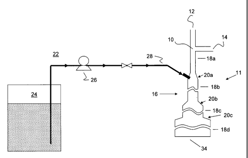
[0031] As shown in Figure 1, a particulate filler slurry is fed into a mixing
portion 10
of a coagulum reactor 11 via a filler feed line 12. An elastomer latex is fed
into mixing
portion 10 via latex feed line 14. The latex begins to coagulate in the mixing
portion
10, and the coagulating mixture, including elastomer and particulate filler,
proceeds
through a diffuser portion 16 of coagulum reactor 11. As shown in Figure 1,
the
diffuser portion 16 has a series of sections 18a-18d, each one having
progressively
higher diameter than the previous section 18. Preferably, transition regions
20a-c
provide a gradual increase in diameter from one section 18 to the next. One of
skill in
the art will recognize that the diffuser portion may have greater or fewer
sections 18
than shown in the figure.
[0032] The second elastomer latex, is introduced via injection system 22.
Injection
system 22 includes a holding tank 24 and a pump 26 that directs the second
elastomer
latex into the coagulum reactor 11 via an injection line 28. Preferably, pump
26 is
operated to generate sufficient pressure to prevent back flow of the
coagulating mixture
into injection line 28. Other suitable apparatus, e.g., different type pumping
or
compression equipment, may be employed to introduce the second elastomer latex
into
the coagulating mixture. As shown in Figure 1, the second elastomer latex is
injected
into the coagulating mixture in transition region 20a. One of skill in the art
will
recognize that the optimal injection location for the second elastomer latex
may vary
depending on the composition of the coagulating mixture and the second
elastomer
latex.
CA 02773599 2012-03-08
WO 2011/034589 PCT/US2010/002523
9
[0033] Elastomer latex is an emulsion of rubber particles in water. The rubber
in the
particles is a highly viscous fluid of rubber molecules, surrounded by a shell
of
naturally occurring substances that stabilize the rubber particles against
aggregation and
coalescence. Destabilization of the latex causes it to coagulate, i.e, the
rubber particles
aggregate and coalesce with one another. In preferred embodiments, the
velocity of the
particulate filler slurry is significantly higher than that of the first
elastomer latex. The
resulting high shear destabilizes the latex. Without being bound by any
particular
theory, it is believed that rapid mixing of the particulate slurry with the
latex results in
decoration of the rubber particle surface by the particulates, which also
destabilizes the
latex. Filler particles colliding with each other also form agglomerates that
can collide
with and destabilize latex particles. The combination of these factors causes
the
elastomer latex to destabilize; rubber particles aggregate by forming rubber-
rubber
contacts or by bridging through filler particles on their surfaces to form
rubber-filler
composite aggregates.
[0034] Without being bound by any particular theory, it is believed that in
the presence
of excess particulate filler, the rubber particles or small aggregates of
rubber particles
become completely decorated with the filler, with little or no free rubber
surface area to
form rubber-rubber contacts with other rubber particles. This limits the
extent to which
the rubber-filler composite aggregates can further aggregate to form a
continuous
network. Instead, rather than forming a coherent coagulum, the masterbatch
crumb
takes the form of discontinuous composite domains dispersed in an aqueous
phase. The
second elastomer latex introduces fresh latex particles that, because they are
not yet
decorated with filler particles, can bind together the discrete rubber-filler
composite
aggregates to form a continuous rubber-particle composite in the form of a
coherent
coagulum.
[0035] For apparatus similar to that shown in Figure 1, factors influencing
the
coherence of the coagulum include the amount of particulate filler injected
into the
mixing block (e.g., the target filler loading), the filler morphology (e.g.,
surface area,
structure), the residence time of the mixture of the first elastomer latex and
the
particulate filler slurry before introduction of the second elastomer latex,
and the
appropriate mixing of the second elastomer latex into the mixture.
CA 02773599 2012-03-08
WO 2011/034589 PCT/US2010/002523
[0036] According to the theory above, there is a limit beyond which the
introduction of
additional latex will not enable the discrete rubber-filler composite
aggregates to form a
coherent coagulum. That is, if there is excess filler in the mixture after the
rubber
particles have been completely decorated, the rubber particles in the second
elastomer
latex stream will become decorated with the excess filler rather than binding
the existing
rubber-filler aggregates together. Thus, while the use of the second elastomer
latex
stream can increase the filler loading level obtainable while still producing
coherent
coagulum, the potential increase is not infmite. The concentration of the
filler in the
slurry, the feed rate and velocity of the filler slurry into the mixing zone,
and the
proportion of the rubber introduced with second elastomer latex with respect
to the total
rubber in the final composite may all be optimized to maximize the
effectiveness of the
second elastomer latex.
[0037] In certain embodiments, the secondary latex improves the achievable
filler
loading (e.g., elastomer composite produced with this amount of filler has the
morphology of a coherent coagulum) by at least 0.5 phr with respect to
elastomer
composite produced in a continuous wet masterbatch process without secondary
latex,
for example, from 0.5 phr to about 15 phr, from about 1 phr to about 14 phr,
from
about 2 phr to about 13 phr, from about 3 phr to about 12 phr, from about 4
phr to
about 11 phr, from about 5 phr to about 10 phr, from about 6 phr to about 9
phr, from
about 7 phr to about 8 phr, from about 1 phr to about 7 phr, from about 1 phr
to about
6 phr, or from about 1 phr to about 5 phr.
[0038] In certain preferred embodiments, use of secondary latex enables use of
a
continuous wet masterbatch process to produce elastomer composite having at
least 65
phr, for example, at least 70 phr or from 65 to 75 phr, of a carbon black
having a
surface area of at least 95 m2/g, as measured by the statistical thickness
method (STSA),
expressed as square meters per gram of carbon black, according to the
procedure set
forth in ASTM D6556 (STSA) and a structure, measured by dibutyl phthalate
(DBP)
adsorption (ASTM D6854), of at least 80 mL/100g, for example, from 80 mL/100g
to
160 mL/100g. Alternatively or in addition, the use of secondary latex may
enable use
of a continuous process to produce elastomer composite having at least 70 phr,
for
example, at least 75 phr or from 70 phr to 80 phr, of carbon black having a
surface area
CA 02773599 2012-03-08
WO 2011/034589 PCT/US2010/002523
11
of at least 68 m2/g as measured by STSA, for example, at least 75 m2/g, and
structure,
as measured by DBP adsorption, at least 60 mL/100g, for example, from 60
mL/100g
to 160 mL/100g. Alternatively or in addition, use of secondary latex enables
use of a
continuous wet mastermatch process to produce elastomer composite containing
carbon
black having a DBP adsorption of at least 60 mL/100mg, for example, at least
80 mL/100mg, at least 100 mL/100mg or from 60 mL/100mg to 160 mL/100mg, and
having a surface area and being present in an amount that satisfies L -
0.26*S + 94,
for example, L -0.26*S + 97, or L -
0.26*S + 100, or L -0.26*S + 104, or -
0.26*S + 94 L -
0.26*S + 110, where L is the amount of carbon black in the
elastomer composite in parts per hundred of rubber (phr) and S is the surface
area in
m2/g measured as STSA (ASTM D6556), where S is optionally at least 65 m2/g ,
at
least 95 m2/g, at least 110 m2/g, or from 65 m2/g to 400 m2/g, for example
from 65
m2/g to 220 m2/g, from 95 m2/g to 200 m2/g, or from 110 m2/g to 180 m2/g.
[0039] Furthermore, according to the above theory, the effectiveness of the
second
elastomer latex will be maximized if it is not introduced until substantially
all the filler
has been adsorbed onto the rubber particles in the first elastomer latex.
Otherwise, the
secondary latex particles become decorated with the filler rather than binding
the
existing rubber-filler aggregates. The time required for the filler slurry and
the
elastomer latex to mix together and allow the filler particles to adsorb onto
the rubber
particles depends in part on how energetically the two fluids are mixed
together. For
apparatus similar to that depicted in Figure 1, when the first elastomer latex
is fed into
mixing portion 10 at a velocity of less than about 10 m/s, for example, from
about 1 to
about 10 m/s, from about 1.5 to about 8 m/s, from about 2 to about 6 m/s, from
about
3 to about 5 m/s, or about 4 m/s to about 7 m/s, and the particulate filler
slurry is fed
into mixing portion 10 at a velocity of at least 30 m/s, for example, about 30
to about
250 ni/s or about 60 to about 150 m/s, a preferred residence time before
injection of the
secondary latex, i.e., the time required for the mixture of the particulate
slurry to travel
from the mixing portion 10 to the location where the secondary latex is
injected, is from
about 1 x 10⁻² s to about 6 x 10⁻² s, for example, from 1.5 x 10⁻² s to about
5.5 x 10⁻² s,
from about 1.85 x 10⁻² s to about 5 x 10' s, from about 2 x 10' s to about 4 x
10-2 s,
from about 2.25 x 10⁻² s to about 3.5 x 10⁻² s, from about 2.1 x 10⁻² s to
about 3 x 10'
CA 02773599 2012-03-08
WO 2011/034589 PCT/US2010/002523
12
s, or from about 2.25 x 10' s to about 2.9 x 10⁻² s. We have also found that
excessive
residence time before the introduction of the second elastomer latex reduces
the
maximum filler loading before the resulting coagulum is discontinuous rather
than
coherent. Without being bound by any particular theory, this may result from
incomplete mixing of the second elastomer latex into the coagulating mixture
of the first
elastomer latex and particulate filler slurry, reducing the effectiveness of
the secondary
latex. We have found that if the second elastomer latex is injected too far
downstream
in the diffuser, it does not thoroughly blend into the flow of the coagulating
mixture.
The residence time may be varied to optimize various operating conditions;
suitable
ranges may vary with the production rate.
[0040] The physical configuration of the injection system 22 also may be
adjusted to
optimize the mixing of the second elastomer latex into the mixture. The
initial flow of
the coagulating mixture through the upstream portions of the diffuser is
relatively
turbulent. This turbulence gradually subsides as the coagulating mixture
proceeds
downstream, and the flow of the coagulum from the outlet 34 of the diffuser is
roughly
laminar. Without being bound by any particular theory, it is believed that the
turbulence
associated with the expansion of the flow cross-section between the first and
second
sections 18a and 18b at transition 20a facilitates mixing of the second
elasomer latex
injected at that point into the coagulating rubber-filler composite. Other
factors
influencing mixing and turbulence include the distance from the point of
slurry
injection, the injection velocity, the difference in cross-sectional area
between the first
and second diffuser sections, the injection velocity of the secondary latex
stream, and
the angle of injection of the secondary latex stream.
[0041] For example, the second section of the diffuser 18b may have a cross-
sectional
area from about 1.2-3.5 times the cross-sectional area of the first section of
the diffuser
18a, for example, from about 1.2 to about 1.4 times, from about 1.4 to about
1.6 times,
from about 1.5 to about 1.7 times, from about 1.7 to 1.9 times, from about 1.9
to about
2.1 times, from about 2.1 to about 2.3 times, from about 2.3 to about 2.5
times, from
about 2.5 to about 2.7 times, from about 2.7 to about 2.9 times, from about
2.9 to
about 3.1 times, from about 3.1 times to about 3.3 times, or from about 3.3 to
about
3.5 times greater. In specific examples, the ratio of the cross-sectional
areas of sections
CA 02773599 2013-10-15
13
18b and 18a may be about 2, about 2.5, or about 3. The lengths of the various
sections
of the diffuser 18a-18d and the dimensions of the downstream sections 18c and
18d may
be as described in U.S. Patent No. 6,048,923.
In certain embodiments, the length of first section 18a may be
from about 2 inches (5.08 cm) to about 9 inches (35.8 cm), for example, from
about 2
inches (5.08 cm) to about 3 inches (7.62 cm), from about 3 inches (7.62 cm) to
about 4
inches (10.2 cm), from about 4 inches (10.2 cm) to about 5 inches (12.7 cm),
from
about 5 inches (12.7 cm) to about 6 inches (15.2 cm), from about 6 inches
(15.2 cm) to
about 7 inches (17.8 cm), from about 7 inches (17.8 cm) to about 8 inches
(20.3 cm),
or from about 8 inches (20.3 cm) to about 9 inches (35.8 cm). The optimal
length may
vary and generally increases with the production rate.
[0042] An exemplary approach for introducing 1the second elastomer latex to
the
coagulating mixture is illustrated in Figure 2. As shown in Figure 2, the
second
elastomer latex is introduced into the coagulating mixture via a nipple 40
that connects
injection line 28 to injector 42 having injection orifice 42a. An o-ring 44
may be used
to improve the seal within nipple 40. While injector 42 is shown injecting the
second
elastomer latex into the coagulating mixture at a 45 degree angle to an axis
of the
coagulum reactor, one of skill in the art will recognize that the angle and
injector size
may be varied depending on the composition of the coagulating mixture and of
the
second elastomer latex. For example, when injector 42 is at a right angle to
the wall of
transition area 20a, the angle a of the transition area 20a may be from 0.5
to 25 , for
example, from 0.50 to 10, from 10 to 20, from 2 to 30, from 30 to 40, from 40
to 50, from
to 6 , from 6 to 70, from 7 to 8 , from 8 to 90, from 9 to 10 , from 10
to 110,
from 11 to 12 , from 12 to 13 , from 13 to 14 , from 14 to 15 , from 15
to 16 ,
from 16 to 17 , from 17 to 18 , from 18 to 19 , from 19 to 20 , from 20
to 21 ,
from 21 to 22 , from 22 to 23 , from 23 to 24 , or from 24 to 25 . In
another
example, the interior diameter of injection orifice 42a may vary from 0.045 to
0.25
inches or even larger depending on the size of the diffuser portion 16. For
example, the
interior diameter of injection orifice 42a may be from 0.045 inches (0.11 cm)
to 0.055
inches (0.14 cm), from 0.055 inches (0.14 cm) to 0.06 inches (0.15 cm), from
0.06
inches (0.15 cm) to 0.065 inches (0.17 cm), from 0.065 inches (0.17 cm) to
0.07 inches
=
CA 02773599 2012-03-08
WO 2011/034589 PCT/US2010/002523
14
(0.18 cm), from 0.07 inches (0.18 cm) to 0.075 inches (0.19 cm), from 0.075
inches
(0.19 cm) to 0.08 inches (0.20 cm), from 0.08 inches (0.20 cm) to 0.09 inches
(0.23
cm), from 0.09 inches (0.23 cm) to 0.1 inches (0.25 cm), from 0.1 inches (0.25
cm) to
0.125 inches (0.32 cm), from 0.125 inches (0.32 cm) to 0.15 inches (0.38 cm),
from
0.15 inches (0.38 cm) to 0.175 inches (0.44 cm), from 0.175 inches (0.44 cm)
to 0.2
inches (0.51 cm), from 0.2 inches (0.51 cm) to 0.225 inches (0.57 cm), or from
0.225
inches (0.57 cm) to 0.25 inches (0.64 cm). One of skill in the art will
recognize that
the size of the injection orifice may be varied depending, e.g., on the
desired flow rate
and pressure. For example, the injection pressure may be from 2-8 bar (0.2-0.8
MPa),
from 3-8 bar (0.3-0.8 MPa), 4-7 bar (0.4-0.7 MPa), or 5-6 bar (0.5-0.6 MPa).
Other
suitable designs may also be employed. For example, the injection orifice may
be
gradually tapered inwardly with respect to injector 42 or may have the same
diameter as
injector 42.
[0043] The second elastomer latex may have the same composition as that used
to
prepare the coagulating mixture, or it may differ in some way. For example,
the
second elastomer latex may be an elastomer latex from a different source or
with a
different concentration of rubber and fluid. Alternatively or in addition, it
may be
subjected to different chemical modifications (including no modification) than
the first
elastomer latex.
[0044] In certain embodiments, at least one of and preferably both the first
elastomer
latex (i.e., the elastomer latex in the coagulating mixture) and the second
elastomer
latex are prepared from a natural rubber latex. Exemplary natural rubber
latices include
but are not limited to field latex, latex concentrate (produced, for example,
by
evaporation, centrifugation or creaming), skim latex (a by-product of the
centrifugation
of natural rubber latex) and blends of any two or three of these in any
proportion. The
latex should be appropriate for the wet masterbatch process selected and the
intended
purpose or application of the final rubber product. The latex is provided
typically in an
aqueous carrier liquid. Selection of a suitable latex or blend of latices will
be well
within the ability of those skilled in the art given the benefit of the
present disclosure
and the knowledge of selection criteria generally well recognized in the
industry.
CA 02773599 2012-03-08
WO 2011/034589 PCT/US2010/002523
[0045] The natural rubber latex may also be chemically modified in some
manner. For
example, it may be treated to chemically or enzymatically modify or reduce
various
non-rubber components, or the rubber molecules themselves may be modified with
various monomers or other chemical groups such as chlorine. Exemplary methods
of
chemically modifying natural rubber latex are disclosed in European Patent
Publications
Nos. 1489102, 1816144, and 1834980, Japanese Patent Publications Nos.
2006152211,
2006152212, 2006169483, 2006183036, 2006213878, 2006213879, 2007154089, and
2007154095, US Patents Nos. 6841606 and 7312271, and U.S. Patent Publication
No.
2005-0148723. Other methods known to those of skill in the art may be employed
as
well.
[0046] In an alternative embodiment, at least one of the first elastomer latex
(i.e., the
elastomer latex in the coagulating mixture) and the second elastomer latex is
prepared
using synthetic elastomer latex. The elastomer of the synthetic elastomer
latex may
have a glass transition temperature (Tg) as measured by differential scanning
calorimetry rangingfrom about -120 C to about 20 C. The synthetic latex may be
a
latex of rubber or "diene" elastomer. The term "diene" elastomer or rubber
should be
understood as meaning, in a known way, an (one or more are understood)
elastomer
resulting at least in part (i.e., a homopolymer or a copolymer) from diene
monomers
(monomers carrying two carbon-carbon double bonds which may or may not be
conjugated).
[0047] These diene elastomers can be classified into two categories:
"essentially
unsaturated" or "essentially saturated". The term "essentially unsaturated" is
understood to mean generally a diene elastomer resulting at least in part from
conjugated diene monomers having a level of units of diene origin (conjugated
dienes)
which is greater than 15% (mol%); thus it is that diene elastomers such as
butyl rubbers
or copolymers of dienes and of a-olefins of EPDM type do not come within the
preceding definition and can in particular be described as "essentially
saturated" diene
elastomers (low or very low level of units of diene origin, always less than
15%). In the
category of "essentially unsaturated" diene elastomers, the term "highly
unsaturated"
diene elastomer is understood to mean in particular a diene elastomer having a
level of
units of diene origin (conjugated dienes) which is greater than 50%.
CA 02773599 2012-03-08
WO 2011/034589 PCT/US2010/002523
16
[0048] Synthetic diene elastomer of the first elastomer latex or of the second
elastomer
latex in accordance with the invention is preferably chosen from the group of
the highly
unsaturated diene elastomers consisting of polybutadienes (abbreviated to
"BR"),
synthetic polyisoprenes (IR), butadiene copolymers, isoprene copolymers and
the
mixtures of these elastomers. Such copolymers are more preferably chosen from
the
group consisting of butadiene/styrene copolymers (SBR), isoprene/butadiene
copolymers (BIR), isoprene/styrene copolymers (SIR) and
isoprene/butadiene/styrene
copolymers (SBIR).
[0049] The elastomers can, for example, be block, random, sequential or
microsequential elastomers and can be prepared in dispersion or in solution;
they can be
coupled and/or star-branched or also functionalized with a coupling and/or
star-
branching or functionalization agent. For coupling with carbon black, mention
may be
made, for example, of functional groups comprising a C-Sn bond or of aminated
functional groups, such as benzophenone, for example; for coupling with a
reinforcing
inorganic filler, such as silica, mention may be made, for example, of silanol
functional
groups or polysiloxane functional groups having a silanol end (such as
described, for
example, in US 6 013 718), of alkoxysilane groups (such as described, for
example, in
US 5 977 238), of carboxyl groups (such as described, for example, in US 6 815
473 or
US 2006/0089445) or of polyether groups (such as described, for example, in
US 6 503 973). Mention may also be made, as other examples of such
functionalized
elastomers, of elastomers (such as SBR, BR, NR or IR) of the epoxidized type.
[0050] The following are preferably suitable: polybutadienes, in particular
those having
a content of 1,2-units from 4% to 80% or those having a content of cis-1,4-
units of
greater than 80%, polyisoprenes, butadiene/styrene copolymers in particular
those
having a styrene content from 5% to 70% by weight, more particularly from 10%
to
50%, for example, from 20% to 40% by weight or from about 23% to about 28% by
weight, a content of 1,2-bonds of the butadiene part from 4% to 65% and a
content of
trans-1,4-bonds from 20% to 80%, butadiene/isoprene copolymers, in particular
those
having an isoprene content from 5% to 90% by weight and a glass transition
temperature ("Tg" - measured according to ASTM D 3418-82) of -40 C to -80 C,
or
CA 02773599 2012-03-08
WO 2011/034589 PCT/US2010/002523
17
isoprene/styrene copolymers, in particular those having a styrene content from
5% to
50% by weight and a Tg from -25 C to -50 C.
[0051] In the case of butadiene/styrene/isoprene copolymers, those having a
styrene
content of from 5% to 50% by weight and more particularly from 10% to 40%, an
isoprene content from 15% to 60% by weight and more particularly from 20% to
50%,
a butadiene content from 5% to 50% by weight and more particularly from 20% to
40%, a content of 1,2-units of the butadiene part from 4% to 85%, a content of
trans-1,4-units of the butadiene part from 6% to 80%, a content of 1,2- plus
3,4-units
of the isoprene part from 5% to 70% and a content of trans-1,4-units of the
isoprene
part from 10% to 50%, and more generally any butadiene/styrene/isoprene
copolymer
having a Tg from -20 C to -70 C, are suitable in particular.
[0052] Exemplary synthetic elastomers include, but are not limited to, rubbers
and
polymers (e.g., homopolymers, copolymers and/or terpolymers) of 1,3-butadiene,
styrene, isoprene, isobutylene, 2,3-dialky1-1,3-butadiene, where alkyl may be
methyl,
ethyl, propyl, etc., acrylonitrile, ethylene, and propylene and the like.
Examples
include, but are not limited to, styrene-butadiene rubber (SBR),
polybutadiene,
polyisoprene, poly(styrene-co-butadiene), polymers and copolymers of
conjugated
dienes such as polybutadiene, polyisoprene, polychloroprene, and the like, and
copolymers of such conjugated dienes with an ethylenic group-containing
monomer
copolymerizable therewith such as styrene, methyl styrene, chlorostyrene,
acrylonitrile,
2-vinyl-pyridine, 5-methyl-2-vinylpyridine, 5-ethyl-2-vinylpyridine, 2-methy1-
5-
vinylpyridine, allyl-substituted acrylates, vinyl ketone, methyl isopropenyl
ketone,
methyl vinyl either, alphamethylene carboxylic acids and the esters and amides
thereof
such as acrylic acid and dialkylacrylic acid amide. Blends and/or oil extended
derivatives of any of the elastomers discussed herein may also be used. Also
suitable
for use herein are copolymers of ethylene and other high alpha olefins such as
propylene, butene-1 and pentene-1.
[0053] In some embodiments, it may be desirable to inject a coagulant, for
example, a
salt or acid solution, along with the elastomer latex stream, to promote
coagulation of
the elastomer.
CA 02773599 2012-03-08
WO 2011/034589 PCT/US2010/002523
18
[0054] The particulate filler fluid may be a carbon black slurry or any other
suitable
filler in a suitable carrier fluid. Selection of the carrier fluid will depend
largely upon
the choice of particulate filler and upon system parameters. Both aqueous and
non-
aqueous liquids may be used, with water being preferred in many embodiments in
view
of its cost, availability and suitability of use in the production of carbon
black and
certain other filler slurries. Small amounts of water-miscible organic
solvents may also
be included in aqueous carrier fluids.
[0055] Selection of the particulate filler or mixture of particulate fillers
will depend
largely upon the intended use of the elastomer masterbatch product. As used
here,
particulate filler can include any material which is appropriate for use in
the
masterbatch process used to produce the masterbatch crumb. Suitable
particulate fillers
include, for example, conductive fillers, reinforcing fillers, fillers
comprising short
fibers (typically having an L/D aspect ratio less than 40), flakes, etc. In
addition to
carbon black and silica-type fillers, discussed in more detail below, fillers
can be
formed of clay, glass, polymer, such as aramid fiber, etc. It is expected that
any filler
suitable for use in elastomer compositions may be incorporated into elastomer
composites according to various embodiments of the invention. Of course,
blends of the
various particulate fillers discussed herein may also be used.
[0056] When a carbon black filler is used, selection of the carbon black will
depend
largely upon the intended use of the elastomer masterbatch product.
Optionally, the
carbon black filler can include also any material which can be slurried and
combined
with a latex in the particular wet masterbatch process selected by the skilled
artisan.
Exemplary particulate fillers include but are not limited to carbon black,
fumed silica,
precipitated silica, coated carbon black, chemically functionalized carbon
blacks, such
as those having attached organic groups, and silicon-treated carbon black,
either alone
or in combination with each other. Exemplary carbon blacks include ASTM N100
series - N900 series carbon blacks, for example N100 series carbon blacks,
N200 series
carbon blacks, N300 series carbon blacks, N700 series carbon blacks, N800
series
carbon blacks, or N900 series carbon blacks. Elastomer composites containing
ASTM
N100, N200, and/or N300 series blacks and/or carbon blacks having similiarly
high or
higher surface areas, e.g, a surface area measured by the statistical
thickness method
CA 02773599 2013-10-15
. .
19
(STSA), expressed as square meters per gram of carbon black, according to the
procedure set forth in ASTM D6556 (STSA) of 68 m2/g or greater, for example,
75
m2/g or greater or 95 m2/g or greater, for example, from 68 m2/g to 400 m2/g
may
especially benefit from the teachings herein. In certain preferred
embodiments, such
carbon blacks have a structure, as measured by dibutyl phthalate adsorption,
of at least
60 mL/100g, for example, at least 80 mL/100g, or from 60 mL/100g to 160
mL/100g.
Carbon blacks sold under the Regal , Black Pearls , Spheron , Sterling , and
Vulcan
trademarks available from Cabot Corporation, the Raven , Statex , Furnex , and
Neotex trademarks and the CD and HV lines available from Columbian Chemicals,
and the Corax , Durax , Ecorax , and Purex trademarks and the CK line
available
from Evonik (Degussa) Industries, and other fillers suitable for use in rubber
or tire
applications, may also be exploited for use with various embodiments. Suitable
chemically functionalized carbon blacks include those disclosed in
International
Application No. PCT/US95/16194 (WO 96/18688).
[0057] Both silicon-coated and silicon-treated carbon blacks may be employed
in
various embodiments. In silicon-treated carbon black, a silicon containing
species such
as an oxide or carbide of silicon is distributed through at least a portion of
the carbon
black aggregate as an intrinsic part of the carbon black. Conventional carbon
blacks
exist in the form of aggregates, with each aggregate consisting of a single
phase, which
is carbon. This phase may exist in the form of a graphitic crystallite and/or
amorphous
carbon, and is usually a mixture of the two forms. Carbon black aggregates may
be
modified by depositing silicon-containing species, such as silica, on at least
a portion of
the surface of the carbon black aggregates. The result may be described as
silicon-
coated carbon blacks.
[0058] The materials described herein as silicon-treated carbon blacks are not
carbon
black aggregates which have been coated or otherwise modified, but actually
represent a
different kind of aggregate having two phases. One phase is carbon, which will
still be
present as graphitic crystallite and/or amorphous carbon, while the second
phase is
silica (and possibly other silicon-containing species). Thus, the silicon-
containing
species phase of the silicon-treated carbon black is an intrinsic part of the
aggregate; it
CA 02773599 2012-03-08
WO 2011/034589 PCT/US2010/002523
is distributed throughout at least a portion of the aggregate. A variety of
silicon-treated
blacks are available from Cabot Corporation under the EcoblackTM name. It will
be
appreciated that the multiphase aggregates are quite different from the silica-
coated
carbon blacks mentioned above, which consist of pre-formed, single phase
carbon black
aggregates having silicon-containing species deposited on their surface. Such
carbon
blacks may be surface-treated in order to place a silica functionality on the
surface of
the carbon black aggregate as described in, e.g., U.S. Patent No. 6,929,783.
.[0059] One or more additives also may be pre-mixed, if suitable, with the
particulate
slurry or with the elastomer latex fluid or may be combined with the mixture
of these
during coagulation. Additives also can be mixed into the coagulating mixture.
Numerous additives are well known to those skilled in the art and include, for
example,
antioxidants, antiozonants, plasticizers, processing aids (e.g., liquid
polymers, oils and
the like), resins, flame-retardants, extender oils, lubricants, coupling
agents, and a
mixture of any of them. Exemplary additives include but are not limited to
zinc oxide
and stearic acid. The general use and selection of such additives is well
known to those
skilled in the art. It should be understood that the elastomer composites
disclosed here
include vulcanized compositions (VR), thermoplastic vulcanizates (TPV),
thermoplastic
elastomers (TPE) and thermoplastic polyolefms (TPO). TPV, TPE, and TPO
materials
are further classified by their ability to be extruded and molded several
times without
loss of performance characteristics.
[0060] The fraction of the second elastomer with respect to the total rubber
in the
composite (i.e., the amount of rubber contributed to the coagulum by the
second
elastomer latex with respect to the total amount of rubber in the coagulum)
may be
adjusted, e.g., by adjusting the relative flow rates of the two elastomer
latices. Other
variables that may be manipulated to optimize the filler loading include the
absolute
flow rate of the first elastomer latex and filler slurry (e.g., the production
rate), the
relative flow rate of the first elastomer latex and filler slurry (e.g., the
filler loading),
the location where the second elastomer latex is injected, and the size of
injector 42.
The fraction of the second elastomer with respect to total rubber may be from
about 0.5
wt% to about 50 wt%, for example from about 1 wt% to about 45 wt%, from about
5
wt% to about 40 wt%, from about 10 wt% to about 15 wt%, from about 15 wt% to
CA 02773599 2012-03-08
WO 2011/034589 PCT/US2010/002523
21
about 20 wt%, from about 20 wt% to about 25 wt%, from about 25 wt% to about 30
wt%, from about 30 wt% to about 35 wt%, from about 35 wt% to about 40 wt%, or
from about 40 wt% to about 45 wt%. In certain embodiments, the fraction may be
from about 16 wt% to about 38 wt%. The proportion of the second elastomer that
may
be used depends in part on the desired composition but may be physically
limited
depending on the amount of the first elastomer latex that should be injected
into mixing
portion 10 to generate the initial coagulating mixture.
[0061] The amount of filler in the elastomer composite may be any amount of
filler that
is used to make elastomer composites. For example, rubbers may be produced
with at
least about 10 phr (parts per hundred of rubber by weight), at least about 20
phr, at
least about 30 phr, at least about 40 phr, at least about 50 phr, at least
about 55 phr, at
least about 60 phr, at least about 65 phr at least about 70 phr, at least
about 75 phr, at
least about 80 phr, at least about 85 phr, at least about 90 phr, at least
about 95 phr, or
at least about 100 phr of filler. However, the teachings herein will provide
greater
advantages with respect to other wet masterbatch methods at higher loadings of
filler,
for example, from about 40 phr to about 100 phr, from about 50 phr to about 95
phr,
from about 55 phr to about 90 phr, from about 60 phr to about 85 phr, from
about 60
phr to about 80 phr, from about 65 phr to about 75 phr, or from about 45 phr
to about
70 phr. One of skill in the art will recognize that what constitutes a "high
loading" will
depend on the morphology of the filler, including, e.g., its surface area and
structure.
[0062] In some embodiments, the use of secondary latex increases the maximum
filler
loading (e.g., the maximum loading of filler while producing a coherent
coagulum), by
about 3% to about 30%, for example, from about 3% to about 5%, from about 5%
to
about 10%, from about 10% to about 15%, from about 15% to about 20%, from
about
20% to about 25%, or from about 25% to about 30%, with respect to the maximum
loading of filler while producing a coherent coagulum without the use of
secondary
latex.
[0063] The masterbatch crumb produced from the first elastomer latex, the
particulate
filler slurry, and the second elastomer latex emerges from the discharge end
of the
coagulum reactor as a substantially constant flow of coagulum concurrently
with the on-
going feeding of the elastomer latices and particulate filler slurry streams
into the
CA 02773599 2012-03-08
WO 2011/034589 PCT/US2010/002523
22
coagulum reactor 11. Preferably, the masterbatch crumb is in the form of a
"coherent
coagulum," a continuous composite in which the carbon black is dispersed
within the
coagulated latex, rather than a discontinuous flow of composite in which
discrete
globules of coagulated latex are separated by an aqueous carrier. Nonetheless,
discontinuous coagulum may be processed by manual or batch dewatering methods,
followed by thermal drying. Preferably, continuous coagulum is created and
then
formed into a desirable extrudate, for example, having about 70-85% water
content.
After formulation, the resulting masterbatch crumb may be passed to suitable
drying
and compounding apparatus.
[0064] In one embodiment, the masterbatch crumb is passed from coagulum
reactor 11
to a de-watering extruder via a simple gravity drop or other suitable
apparatus known to
those of skill in the art. The dewatering extruder may bring the elastomer
composite
from, e.g., approximately 70-85% water content, to a desired water content,
e.g.,
approximately 1% to 20% water content. The optimal water content may vary with
the
elastomer employed, the type of filler, and the desired downstream processing
procedure. Suitable de-watering extruders are well known and commercially
available
from, for example, the French Oil Mill Machinery Co. (Piqua, Ohio, USA).
[0065] After de-watering, the resulting dewatered coagulum may be dried. In
certain
embodiments, the dewatered coagulum is simply thermally dried. Preferably, the
dewatered coagulum emerging from the de-watering extruder is mechanically
masticated
while drying. For example, the dewatered coagulum may be mechanically worked
with
one or more of a continuous mixer, an internal mixer, a twin screw extruder, a
single
screw extruder, or a roll mill. Suitable masticating devices are well known
and
commercially available, including for example, a Unimix Continuous Mixer and
MVX
(Mixing, Venting, eXtruding) Machine from Farrel Corporation of Ansonia,
Conn., a
long continuous mixer from Pomini, Inc., a Pomini Continuous Mixer, twin rotor
corotating intermeshing extruders, twin rotor counterrotating non-intermeshing
extruders, Banbury mixers, Brabender mixers, intermeshing-type internal
mixers,
kneading-type internal mixers, continuous compounding extruders, the biaxial
milling
extruder produced by Kobe Steel, Ltd., and a Kobe Continuous Mixer.
Alternative
masticating apparatus suitable for use with various embodiments of the
invention will be
CA 02773599 2013-10-15
23
familiar to those of skill in the art. Exemplary methods for mechanically
masticating
dewatered composite are disclosed in U.S. Patents Nos. 6,929,783 and
6,841,606, and
PCT Application No. US09/000732 .
[0066] In certain embodiments, additives can be combined with the dewatered
coagulum
in the mechanical mixer. Specifically, additives such as filler (which may be
the same
as, or different from, the filler used in the coagulum reactor; exemplary
fillers include
silica and zinc oxide, with zinc oxide also acting as a curing agent), other
elastomers,
other or additional masterbatch, antioxidants, antiozonants, plasticizers,
processing aids
(e.g., stearic acid, which can also be used as a curing agent, liquid
polymers, oils,
waxes, and the like), resins, flame-retardants, extender oils, lubricants, and
a mixture
of any of them, can be added in the mechanical mixer. In certain other
embodiments,
additional elastomers can be combined with the dewatered coagulum to produce
elastomer blends. Exemplary elastomers include, but are not limited to,
rubbers,
polymers (e.g., homopolymers, copolymers and/or terpolymers) of 1,3-butadiene,
styrene, isoprene, isobutylene, 2,3-dialky1-1,3-butadiene, where alkyl may be
methyl,
ethyl, propyl, etc., acrylonitrile, ethylene, and propylene and the like.
Methods of
producing masterbatch blends are disclosed in our commonly owned U.S. Patents
Nos.
7,105,595, 6,365,663, and 6,075,084.
Alternatively or in addition, traditional
compounding techniques may be used to combine vulcanization agents and other
additives known in the art with the dewatered coagulum or, where a masticating
apparatus is used to dry the material, the resulting masticated masterbatch,
depending
on the desired use.
[0067] In certain embodiments, elastomer composite may be used in or produced
for
use in various parts of a tire, for example, tires, tire treads, tire
sidewalls, wire-skim
for tires, and cushion gum for retread tires. Additional, non-tire,
applications for these
elastomer composites include but are not limited to rubber components of
engine
mounts, rank tracks, mining belts, rubber components of hydro-mounts, bridge
bearings, seismic isolators, tracks and track pads for track-propelled
equipment such as
bulldozers, etc., mining equipment such as screens, mining equipment linings,
conveyor
belts, chute liners, slurry pump liners, mud pump components such as
impellers, valve
CA 02773599 2012-03-08
WO 2011/034589 PCT/US2010/002523
24
seats, valve bodies, piston hubs, piston rods, and plungers, impellers for
various
applications such as mixing slurries and slurry pump impellers, grinding mill
liners,
cyclones and hydrocyclones, and expansion joints, marine equipment such as
linings for
pumps (e.g., outboard motor pumps, dredge pumps), hoses (e.g., dredging hoses
and
outboard motor hoses), and other marine equipment, shaft seals for marine,
oil,
aerospace, and other applications, propeller shafts, linings for piping to
convey, e.g.,
oil sands and/or tar sands, and other applications where abrasion resistance
is desired.
[0068] The present invention will be further clarified by the following
examples which
are intended to be only exemplary in nature
EXAMPLES
EXAMPLE 1
Carbon black slurry preparation
[0069] Dry carbon black (grade indicated in Table 1, below, obtained from
Cabot
Corporation) was mixed with water and ground to form a slurry having a
concentration
of about 10-15 wt%. The slurry was fed to a homogenizer at an operating
pressure of
around 3000 psig to produce a finely dispersed carbon black slurry, and the
slurry was
introduced as a jet into the mixing zone. The carbon black flow rate was
adjusted to
about 690-960 kg/hr (wet basis) to modify final carbon black loading levels in
composites produced with field latex and to about 1145 kg/hr (wet basis) when
latex
concentrate was employed.
Table 1
Carbon Black Grade STSA* (m2/g) DBP adsorption**
(mL/100g)
N234 114 125
N134 131 127
Experimental Black 1 154 123
*ASTM D6556
**ASTM D2414
CA 02773599 2012-03-08
WO 2011/034589 PCT/US2010/002523
Primary Latex delivery
[0070] Natural rubber latex materials described in Table 2 (field latex unless
indicated
otherwise in Table 2) were pumped to the mixing zone of the coagulum reactor.
The
latex flow rate was adjusted between about 320-790 kg/h (wet basis) in order
to modify
fmal carbon black loading levels.
Carbon black and latex mixing
[0071] The carbon black slurry and latex were mixed by entraining the latex
into the
carbon black slurry in a mixing portion (e.g., mixing portion 10) of a
coagulum reactor
similar to that shown in Figure 1. During the entrainment process, the carbon
black
was intimately mixed into the latex and the mixture coagulated.
Secondary latex delivery
[0072] Natural rubber latex materials described in Table 2 were pumped into
various
locations downstream of the mixing portion of the coagulum reactor at a
pressure of 3-8
bar starting at a rate of about 80 kg/hour (wet basis). The latex was injected
at a right
angle to the wall of the coagulum reactor to which the injection line (e.g.,
element 28)
is affixed. The pumping rate was gradually increased to at most 300 kg/hr (wet
basis)
until the coagulum emerging from the diffuser exhibited the desired
morphology.
Downstream of the mixing portion, a diffuser portion had a series of sections,
each one
having progressively higher diameter than the previous section, with a beveled
transition portion in between sections. The first section of the diffuser
(e.g., 18a in
Figure 1) was 4 inches (10.2 cm) long; the second section (e.g., 181) in
Figure 1) was 3
inches (7.6 cm) long. The angle of the transition region (e.g. a in Figure 2)
was 7
degrees. The ratio of the diameters of the second section (e.g., 18b in Figure
1) to the
first section (e.g., 18a in Figure 1), was about 1.7. The location into which
the
secondary latex was pumped and the fraction of the rubber from the secondary
latex in
the final product (i.e., the ratio of rubber from the secondary latex with
respect to the
total rubber from the primary and secondary latex streams) are indicated in
Table 2
below. Data shown in bold face reflect the maximum loading achieved for a
particular
location of secondary latex injection, listed in Table 3 below.
Table 2A
CB grade N234 N234
N234 0
t..)
Secondary latex injection
=
control Middle of first section Middle of
second section
,-,
location
(...)
Calculated CB loading after
1st latex, p 56 62 70 75 80 85 90
95 ui
hr
cee
o
Prod. Rate*. Kg/hr 262 255 247 232 227 211 208
203
1st latex DRC**, % 30.7 30.7 30.7 30.7 30.7 30.7
30.7 30.7
2fla latex DRC, % - 30.7 30.7 30.7 30.7 30.7
30.7 30.7
2'd latex DRC/total DRC, % - 31 33 35 36 38
39 40
Residence time before 2nd
1.2 1.2 1.3 1.3 6.5 6.5
6.7
latex addition (10-2 s) 0
Yes,,
Coherent coagulum sometimes Yes Yes Yes Yes Yes
No No 0
I.)
-1
discontinuous -
1
u.)
Measured CB loading, phr 59.7 49.4 54.7 58.4 59.2 62.5
64.2 68.3
t..)
ko
o ko
*Based on carbon black and first latex only
I.)
**Dry Rubber Content
o
H
Table 2B
N)
I
0
CB grade N234 N234 N234
N234 u.)
1
0
Secondary latex injection middle of middle of
1" upstream from the 1" downstream from the
middle 0
location first section second section
middle of 2nd section of 1st section
Calculated CB loading after 1st
67 67 70 69 63
70 72
latex, phr
Prod. Rate*. Kg/hr 253 250 238 237 253
243 237
1st latex DRC**, % 30.7 30.7 30.7 30.7 30.7
30.7 30.7
1-d
2nd latex DRC***, % 14.1 14.1 14.2 14.2 14.0
14.8 14.8 n
1-i
2nd latex DRC/total DRC, % 18 11 12 12 11
19 20
Residence time before 2nd latex
cp
1.2 5.8 4.4 4.5 1.8
1.8 1.9 t..)
o
addition (10-2 s)
,-,
o
Coherent coagulum Yes Yes No Yes Yes
Yes Yes
o
Measured CB loading, phr 59.9 62.1 67 65 62.2
62.5 62.3 t..)
vi
*Based on carbon black and first latex only ** Dry Rubber Content ***DRC
adjusted by dilution with water w
(...)
,
,
,
Table 2C
0
CB grade N234 N234 N234
t..)
o
Secondary latex injection transition between first and
control transition between first and
,-,
location second sections second sections
-a-,
.6.
Calculated CB loading after
77 u,
.79 78 60 87 83 85 cio
1st latex, phr
o
Prod. Rate*. Kg/hr 233 217 217 266 205 221 215
1st latex DRC**, % 30.7 30.7 30.7 28.7 28.7 28.7
28.7
2" latex DRC***, % 13.6 13.6 16.0 - 15.1 15.1 15.1
2" latex DRC/total DRC, % 23 25 28 - 24 22
23
Residence time before 2"
2.6 2.8 2.8 2.8 2.7 2.7
latex addition (10-2 s)
n
Coherent coagulum Yes No Yes No Yes Yes Yes
0
Measured CB loading, phr 69.8 71.5 71.1 59.7 70.2
67.9 68.8 I.)
-.1
*Based on carbon black and first latex only ** Dry Rubber Content ***DRC
adjusted by dilution with water
LO
Ul
N
li)
---.1
ki)
Table 2D I.)
0
CB grade N234
H
"
I
Secondary latex injection Transition between first and second sections
0
u.)
location
1
0
Calculated CB loading after 1st
CO
78 80 82 83 80
latex, phr
Prod. Rate*. Kg/hr 222 221 218 215 214
1st latex DRC**, % 28.7 28.7 28.7 28.7 28.7
2" latex DRC***, A) 14.8 14.8 14.8 14.8 10.7
2" latex DRC/total DRC, % 21 22 22 22 17
1-d
Residence time before 2" latex
n
2.6 2.7 2.7 2.7 2.7
addition (10-2 s)
Coherent coagulum Yes Yes Yes Yes Yes
cp
t..)
Measured CB loading, phr 62.6 66.1 65.9 66.9 66.4
,-,
o
*Based on carbon black and first latex only ** Dry Rubber Content ***DRC
adjusted by dilution with water -a-,
=
t..,
u,
t..,
c,.,
Table 2E
CB grade Experimental Black 1
0
t..)
Secondary latex Control 1" upstream from Transition
between first and second sections o
,-,
,-,
injection location middle of 2nd section
(...)
Calculated CB loading
.6.
49 42 57 52 59 70 55 62 62 79
82 u,
after 1st latex, phr
0
o
Prod. Rate*. kg/hr 272 295 244 323 240 211 243
229 230 199 207
1st latex DRC**, % 28.7 29.6 29.6 29.6 29.6 29.6 29.6
29.6 29.6 29.6 29.6
2nd latex DRC***, % - - 10.7 10.7 10.7 10.7 10.7
27.0 27.0 27.0 29.6
2nd latex DRC/ total
14 10 14 16 9
21 21 36 38
DRC, % - -
Residence time before
4.0 3.1 2.4 2.6 2.4
2.4 2.4 2.7 2.6 0
2nd latex addition (10-2 s)
Coherent coagulum No Yes Yes Yes Yes Yes Yes
Yes Yes Yes Yes 0
I.)
-I
Measured CB loading,
-1
46.3 49.3 51.4 48.4 51.6 54.3 51.3 51.7 51.4 55
54.9 UJ
phr
in
t..)
ko
*Based on carbon black and first latex only ** Dry Rubber Content ***DRC
adjusted by dilution with water oe ko
tv
o
H
Table 2F
"
1
0
CB grade Experimental Black 1
N134 N234 UJ
I
0
Secondary latex injection Transition between first and second
Transition between first and second 0
Control
location sections
sections
Calculated CB loading after
80 84 87 90 60 83
83 87 65
1st latex, phr
Prod. Rate*. kg/hr 286 288 292 302 280 296
303 279 496
1st latex DRC**, % 30.3 30.3 30.3 30.3 29.8
29.8 29.8 _ 29.8 59.3***
2nd latex DRC, % 30.3 30.3 30.3 30.3 --- 29.8
29.8 29.8 59.3*** 1-d
n
2nd latex DRC/total DRC, % 22 27 27 30 --- 17
20 25 27
Residence time before 2nd
latex addition (10-2 s)
2.4 2.4 2.4 2.3 -- 2.3
2.3 2.5 1.9 cp
t..)
o
1-,
Coherent Coagulum Yes Yes Yes Yes Yes Yes
Yes Yes Yes =
Measured (actual) (actual) CB
=
60.3 60.1 59 61.6 54.9
63.5 62.6 64.4 47.8 t-)
loading, phr
u,
t..)
(...)
*Based on carbon black and first latex only ** Dry Rubber Content ***Latex
Concentrate
CA 02773599 2012-03-08
WO 2011/034589
PCT/US2010/002523
29
[0073] For successful examples incorporating secondary latex according to an
embodiment of the invention, a masterbatch crumb exited the coagulum reactor
as a
continuous flow of coherent coagulum. Unsuccessful examples employing
secondary
latex may be contrasted with successful samples having similar operating
conditions; in
general, rubber recovered from such examples contained higher loadings of
carbon
black. Such samples emerged from the coagulum reactor as a discontinuous,
sandy
coagulum that caused the dewatering extruder to back up. Table 3, below, shows
the
maximum loading, i.e., the maximum filler content in the elastomer composite,
in parts
per hundred of rubber (phr), for which coherent coagulum was produced (that
is,
attempts to produce masterbatch crumb with higher filler content did not
result in a
coherent coagulum).
Maximum Carbon Black Loading, phr
Injection point in
diffuser N234 N134
Experimental
Black 1
Control (no 59.7* 54.9 49.3
injection)
Middle of first 59.9
section
1" downstream from
middle of first 62.5
section
Transition between
first and second 71.1 64.4 61.6
section
1" upstream from
middle of the second 65 51.4
section
Middle of second 62.1
section
*coagulum intermittently discontinuous
Table 3
[0074] The results show that operating variables such as the flow rate of the
primary
and secondary latex streams, the production rate, the proportion of secondary
rubber,
CA 02773599 2012-03-08
WO 2011/034589 PCT/US2010/002523
and the carbon black loading may be optimized with respect to one another to
improve
processability and increase filler loading. Figure 3 shows the highest
loadings achieved
with and without secondary latex for the three grades of carbon black
described above.
The results show that while the morphology of the carbon black influences the
= maximum loading that can be achieved while producing coherent coagulum,
the use of
secondary latex provides a clear and consistent improvement in the achievable
loading.
Dewatering
[0075] The masterbatch crumb discharged from the coagulum reactor was
dewatered to
10-20% moisture with a dewatering extruder (The French Oil Machinery Company).
In
the extruder, the masterbatch crumb was compressed, and water squeezed from
the
crumb was ejected through a slotted barrel of the extruder.
Drying and cooling
[0076] The dewatered coagulum was dropped into a continuous compounder (Farrel
Continuous Mixer (FCM), Farrel Corporation) where it was masticated and mixed
with
1 phr of antioxidant (N-(1,3-dimethylbuty1)-N'-phenyl-p-phenylenediamine
(6PPD,
Flexsys, St. Louis, MO). The moisture content of the masticated masterbatch
exiting
the FCM was around 1-2%. The masticated masterbatch was further masticated and
cooled on an open mill to form a dried elastomer composite. The actual carbon
black
loading levels were determined by nitrogen pyrolysis (values listed on Tables
2A-2E) or
TGA (values listed on Table 2F) on dried product. The dried elastomer
composite was
vulcanized; the mechanical properties of the vulcanized elastomer composite
(e.g., tan
delta, ratio of stresses at 300% and 100% strain) exhibited a variation with
loading
similar to that of vulcanized elastomer composites having lower filler
loadings and
prepared using the same techniques but without secondary latex. The use of
secondary
latex injection enables the manufacture of more highly loaded elastomer
composites
without sacrificing performance of the final rubber compounds.
=
CA 02773599 2012-03-08
WO 2011/034589 PCT/US2010/002523
31
EXAMPLE 2
Filler slurry preparation
[0077] Silicon-treated carbon black (CR)(TM 2000 ECOBLACK silicon-treated
carbon
black, available from Cabot Corporation) is mixed with water and ground to
form a
slurry having a concentration of about 10-15 wt%. The slurry is fed to a
homogenizer
at an operating pressure of around 3000 psig to produce a finely dispersed
carbon black
slurry, and the slurry is introduced as a jet into the mixing zone. The slurry
flow rate is
adjusted to about 690-960 kg/hr (wet basis) to modify fmal filler loading
levels in
composites produced with field latex and to about 1145 kg/hr (wet basis) when
latex
concentrate is employed.
Primary Latex delivery
[0078] Either field latex having a dry rubber content of about 27-31% or
natural rubber
latex concentrate is pumped to the mixing zone of the coagulum reactor. The
latex flow
rate is adjusted between about 320-790 kg/h (wet basis) in order to modify
final filler
loading levels.
Filler and latex mixing
[0079] The filler slurry and latex are mixed by entraining the latex into the
filler slurry
in a mixing portion (e.g., mixing portion 10) of a coagulum reactor similar to
that
shown in Figure 1. During the entrainment process, the filler is intimately
mixed into
the latex and the mixture coagulates. Downstream of the mixing portion, a
diffuser
portion has a series of sections, each one having progressively higher
diameter than the
previous section, with a beveled transition portion in between sections.
Secondary latex delivery
[0080] Field latex is pumped into the coagulating mixture of filler slurry and
latex at the
transition between the first and second sections (e.g., 20a in Figure 1) at a
pressure of
3-8 bar starting at a rate of about 80 kg/hour (wet basis). The latex is
injected at a right
angle to the wall of the coagulum reactor. The pumping rate is gradually
increased to at
CA 02773599 2012-03-08
WO 2011/034589 PCT/US2010/002523
32
most 300 kg/hr (wet basis) until the coagulum emerging from the diffuser
exhibits the
desired morphology.
Dewatering
[0081] The masterbatch crumb discharged from the coagulum reactor is dewatered
to
10-20% moisture with a dewatering extruder (The French Oil Machinery Company).
In
the extruder, the masterbatch crumb is compressed, and water squeezed from the
crumb
is ejected through a slotted barrel of the extruder.
Drying and cooling
[0082] The dewatered coagulum is dropped into a continuous compounder (Farrel
Continuous Mixer (FCM), Farrel Corporation) where it is masticated and mixed
with 1
phr of antioxidant (N-(1,3-dimethylbuty1)-N'-phenyl-p-phenylenediamine (6PPD,
Flexsys, St. Louis, MO) and 1.5 phr of a coupling agent (bis-
(triethoxysilylpropyptetrasulfide (TESPT, Si-69, available from Evonik
Industries,
Essen, Germany)). The moisture content of the masticated masterbatch exiting
the
FCM is around 1-2%. The product is further masticated and cooled on an open
mill to
form a dried elastomer composite.
EXAMPLE 3
Filler slurry preparation
[0083] A mixture of carbon black and silica (N234 carbon black, available from
Cabot
Corporation, and HiSil 233 silica, available from PPG Industries, Pittsburgh,
PA) is
mixed with water and ground to form a slurry having a concentration of about
10-15
wt%, in which the ratio of carbon black to silica ranges from 60:40 to 80:20
by mass.
The slurry is fed to a homogenizer at an operating pressure of around 3000
psig to
produce a fmely dispersed carbon black slurry, and the slurry is introduced as
a jet into
the mixing zone. The slurry flow rate is adjusted to about 690-960 kg/hr (wet
basis) to
modify final filler loading levels in composites produced with field latex and
to about
1145 kg/hr (wet basis) when latex concentrate is employed.
CA 02773599 2012-03-08
WO 2011/034589 PCT/US2010/002523
33
Primary Latex delivery
[0084] Either field latex having a dry rubber content of about 27-31% or
natural rubber
latex concentrate is pumped to the mixing zone of the coagulum reactor. The
latex flow
rate is adjusted between about 320-790 kg/h in order to modify fmal filler
loading
levels.
Filler and latex mixing
[0085] The filler slurry and latex are mixed by entraining the latex into the
filler slurry
in a mixing portion (e.g., mixing portion 10) of a coagulum reactor similar to
that
shown in Figure 1. During the entrainment process, the filler is intimately
mixed into
the latex and the mixture coagulates.
Secondary latex delivery
[0086] Field latex is pumped into the coagulating mixture of filler slurry and
latex at the
transition between the first and second sections (e.g., 20a in Figure 1) at a
pressure of
3-8 bar starting at a rate of about 80 kg/hour (wet basis). The latex is
injected at a right
angle to the wall of the coagulum reactor. The pumping rate is gradually
increased to at
most 300 kg/hr (wet basis) until the coagulum emerging from the diffuser
exhibits the
desired morphology.
Dewatering
[0087] The masterbatch crumb discharged from the coagulum reactor is dewatered
to
10-20% moisture with a dewatering extruder (The French Oil Machinery Company).
In
the extruder, the masterbatch crumb is compressed, and water squeezed from the
crumb
is ejected through a slotted barrel of the extruder.
Drying and cooling
[0088] The dewatered coagulum is dropped into a continuous compounder (Farrel
Continuous Mixer (FCM), Farrel Corporation) where it is masticated and mixed
with 1
phr of antioxidant (N-(1,3-dimethylbuty1)-N'-phenyl-p-phenylenediamine (6PPD,
Flexsys, St. Louis, MO) and 1.5 phr of a coupling agent (bis-
(triethoxysilylpropyptetrasulfide (TESPT, Si-69, available from Evonik
Industries,
CA 02773599 2012-03-08
WO 2011/034589 PCT/US2010/002523
34
Essen, Germany)). The moisture content of the masticated masterbatch exiting
the
FCM is around 1-2%. The product is further masticated and cooled on an open
mill to
form a dried elastomer composite.
EXAMPLE 4
[0089] Dry carbon black (N234, obtained from Cabot Corporation) was mixed with
water and ground to form a slurry having a concentration of about 10-15 wt%.
The
slurry was fed to a homogenizer at an operating pressure of around 3000 psig
to
produce a finely dispersed carbon black slurry, and the slurry was introduced
as a jet
into the mixing zone. The carbon black flow rate (dry basis) is specified in
Table 4,
below.
Primary Latex delivery
[0090] Field latex having a dry rubber content of about 27-31% was pumped to
the
mixing zone of the coagulum reactor. The delivery rate of primary rubber (dry
rubber
basis) into the mixing zone is listed in Table 4, below.
Carbon black and latex mixing
[0091] The carbon black slurry and latex were mixed by entraining the latex
into the
carbon black slurry in a mixing portion (e.g., mixing portion 10) of a
coagulum reactor
similar to that shown in Figure 1. During the entrainment process, the carbon
black
was intimately mixed into the latex and the mixture coagulated.
Secondary latex delivery
[0092] Field latex was pumped into the downstream, diffuser portion of the
coagulum
reactor at the transition between the first and second sections of the
diffuser (e.g., 20a
on Figure 1), and the angle a (see Figure 2) was 7 degrees. The length of the
first
section of the diffuser (e.g., 18a in Figure 1) was varied between 4 and 8.5
inches; the
resulting residence time before introduction of the secondary latex stream is
listed in
Table 4, along with the delivery rate of secondary rubber (dry rubber basis).
The
corresponding residence time for the Comparative Example (i.e., the residence
time in
the first section of the diffuser) was 1.8*10-2 s. The pumping rates of the
primary and
CA 02773599 2012-03-08
WO 2011/034589 PCT/US2010/002523
secondary latex and of the carbon black slurry were adjusted to achieve a
production
rate of 450-500 kg/hr (dry basis).
Comparative
Example 4-1 4-2 4-3 4-4 4-5 4-6
Example
Carbon black flow rate
153 167 197 192 197 195 195
(kg/hr, dry basis)
Primary rubber flow
rate (kg/hr, dry rubber 222 189 209 194 221 186 259
basis)
Secondary rubber flow
rate (kg/hr, dry rubber 0 64 61 66 67 92 42
basis)
Residence time before
1.8 1.9 2.4 3.0 2.4 2.2
r elastomer (10-2 s)
2 elastomer/total
0 25.2 22.5 25.4 23.3 33.3 13.9
elastomer (%)
Measured CB loading
64.5 64.4 65.3 68 64.4 65.6 63.2
(Phr)
Table 4
[0093] Results from Examples 4-1 through 4-4 are shown in Figure 4. Figure 4
clearly
shows an optimum residence time for maximizing filler loading. Such a maximum
is
consistent with the theory described above. According to the theory,
introduction of the
secondary latex stream before substantial decoration of the latex particles
causes the
rubber particles in the secondary latex stream to also become decorated,
rather than
binding rubber-filler aggregates together, while the secondary latex stream is
not
completely mixed with the coagulating mixture if it is introduced too far
downstream.
In Examples 4-5 and 4-6, the injection rate of the secondary rubber flow was
varied
while maintaining a residence time similar to that of Example 4-3. The results
are
consistent with the theory described above; only a certain amount of secondary
latex is
required to bind together the discrete rubber-filler aggregates into a
coherent coagulum,
and additional secondary latex only dilutes the fuial product loading.
Dewatering
[0094] The masterbatch crumb discharged from the coagulum reactor was
dewatered to
10-20% moisture with a dewatering extruder (The French Oil Machinery Company).
In
CA 02773599 2012-03-08
WO 2011/034589 PCT/US2010/002523
36
the extruder, the masterbatch crumb was compressed, and water squeezed from
the
crumb was ejected through a slotted barrel of the extruder.
Drying and cooling
[0095] The dewatered coagulum was dropped into a continuous compounder (Farrel
Continuous Mixer (FCM), Farrel Corporation) where it was masticated and mixed
with
1 phr of antioxidant (N-(1,3-dimethylbuty1)-N'-phenyl-p-phenylenediamine
(6PPD,
Flexsys, St. Louis, MO). The moisture content of the masticated masterbatch
exiting
the FCM was around 1-2%. The product was further masticated and cooled on an
open
mill to form a dried elastomer composite. The actual carbon black loading
levels were
determined by TGA on the dried elastomer composite and are listed in Table 4.
The
dried elastomer composite was vulcanized; the mechanical properties of the
vulcani7ed
elastomer composite (e.g., tan delta, ratio of stresses at 300% and 100%
strain)
exhibited a variation with loading similar to that of vulcanized elastomer
composites
having lower filler loadings and prepared using the same techniques but
without
secondary latex. The use of secondary latex injection enables the
manufacturing of more
highly loaded elastomer composites without sacrificing performance of the
final rubber
compounds.
EXAMPLE 5
[0096] This example demonstrates the improvements to the properties of
vulcanized
rubber compositions prepared with elastomer composites having high volume
fractions
of carbon black prepared according to exemplary embodiments of the invention,
compared to the already improved properties of vulcanized rubber compositions
based
on elastomer composites having lesser volume fraction of carbon black prepared
by a
wet mix method used in Example 4 to prepare control samples and to vulcanind
rubber
compositions prepared by dry mixing.
Preparation of masterbaches
[0097] Masterbaches A were prepared according to Example 1, as follows :
- Masterbatch Al corresponds to N234, measured CB loading of 66.1
phr,
of Table 2D,
CA 02773599 2012-03-08
WO 2011/034589 PCT/US2010/002523
37
- Masterbatch A2 corresponds to Experimental Black 1, measured CB
loading of 59 phr, of Table 2F,
- Masterbatch A3 corresponds to N134, measured CB loading of 64.4 phr,
of Table 2F
[0098] Masterbatches B were prepared with the same carbon black and the same
field
latex according to the wet mix method used in Example 4 to prepare control
samples, as
follows:
- Masterbatch B1 includes 50 phr of N234,
- Masterbatch B2 includes 49 phr of Experimental Black 1,
- Masterbatch B3 includes 50 phr of N134,
Preparation of rubber compositions
[0099] The tests which follow are carried out in the following way: the diene
elastomer
and the reinforcing filler or the masterbatches including diene elastomers and
reinforcing fillers were introduced into an internal mixer, 70% filled and
having an
initial vessel temperature of approximately 50 C, followed, after kneading for
one
minute, by the various other ingredients, with the exception of the sulphur
and
sulphenamide primary accelerator. Thermomechanical working (non-productive
phase)
was then carried out in one or two stages (total duration of the kneading
equal to
approximately 5 min), until a maximum "dropping" temperature of approximately
165 C was reached.
[00100] The mixture thus obtained was recovered and cooled and then sulphur
and
sulphenamide accelerator were added on an external mixer (homofinisher) at 30
C, the
combined mixture was mixed (productive phase) for 3 to 4 minutes.
[00101] The compositions were subsequently either calendered in the form of
plaques
(thickness of 2 to 3 mm), for the measurement of their physical or mechanical
properties.
Rubber compositions
CA 02773599 2012-03-08
WO 2011/034589 PCT/US2010/002523
38
[00102] Rubber compositions CA1 to CA3 and CB1 to CB3 were produced with
masterbatches Al to A3 and B1 to B3, respectively. Comparative rubber
compositions
CD1 to CD3 and CE1 to CE3 were fabricated using a dry mixing process from the
same carbon blacks in dry form and solid natural rubber.
[00103] Thus all the compositions included 100 phr of natural rubber (whether
introduced in the form of a masterbatch or in a solid form) and different
grades of
carbon black as shown in the following Table 5.
Table 5
Composition CD1 CB1 CE1 CA1 CD2 CB2 CE2 CA2 CD3 CB3 CE3 CA3
N234 50 50 66 66.1 -
(phr)
Experimental - - 49 49 59 59 -
Black 1 (phr)
N134 - 50
50 64 64.4
(phr)
[00104] All these compositions also include the additional ingredients shown
in Table
6
Table 6
Ingredients Quantity(phr)
6 PPD 2.0
Stearic Acid 2.5
ZnO 3.0
CBS* (accelerator) 1.2
Sulfur 1.2
* N-Cyclohexy1-2-benzothiazolesulphenamide (Flexsys: "Santocure" CBS)
Characterization of the rubber cormositions
[00105] The diene rubber compositions were characterized before and after
curing as
indicated below.
CA 02773599 2012-03-08
WO 2011/034589 PCT/US2010/002523
39
1. Mooney plasticity
[00106] Use was made of an oscillating consistometer as described in French
Standard NF T 43-005 (1991). The Mooney plasticity measurement was carried out
according to the following principle: the composition in the raw state (i.e.,
before
curing) was moulded in a cylindrical chamber heated to 100 C. After preheating
for
one minute, the rotor rotated within the test specimen at 2 revolutions/minute
and the
working torque for maintaining this movement was measured after rotating for 4
minutes. The Mooney plasticity (ML 1+4) is expressed in "Mooney unit" (MU,
with
1 MU=0.83 newton.metre).
2 Dispersion
[00107] In a known way, filler dispersion in rubber matrix can be represented
by Z
value, which was measured, after reticulation, according to the method
described by S.
Otto and Al in Kautschuk Gummi Kunststoffe, 58 Jahrgang, NR 7-8/2005, article
titled
"New Reference value for the description of Filler Dispersion with the
Dispergrader
1000NT" according to standard ISO 11345.
[00108] The calculation of Z value is based on the percentage of undispersed
area, as
measured by the apparatus "disperGRADER+" provided with its procedure and its
operating software "disperDATA" by the Dynisco company according to the
equation:
Z= 100 - (percentage of undispersed area)/0,35
[00109] The percentage of undispersed area was measured using a camera with a
light source at an angle of 30 with respect to the observation surface. Light
dots are
associated with filler and agglomerates, while the dark background is
associated the
rubber matrix; numerical treatment transforms the image into a black and white
image,
and allows the determination of the percentage of undispersed area, as
described by
S.Otto in the above mentioned document.
[00110] The higher the value Z, the better the dispersion of the filler in the
rubber
matrix (a Z value of 100 corresponding to perfect mix and a Z value of 0 to
poorer mix)
3 Rheometry
CA 02773599 2012-03-08
WO 2011/034589 PCT/US2010/002523
[00111] The measurements were carried out at 150 C with an oscillating disc
rheometer, according to Standard DIN 53529 - part 3 (June 1983). The change in
the
rheometric torque as a function of time describes the change in the stiffening
of the
composition as a result of the vulcanization reaction. The measurements are
processed
according to Standard DIN 53529 - part 2 (March 1983): "ti" is the induction
period,
that is to say the time necessary for the start of the vulcanization reaction;
ta (for
example t90) is the time necessary to achieve a conversion of a %, that is to
say a%
(for example 90%) of the difference between the minimum and maximum torques.
The
conversion rate constant, denoted K (expressed in min-1), which is first
order, calculated
between 30% and 80% conversion, which makes it possible to assess the
vulcani7ation
kinetics, was also measured.
4. Tensile tests
[00112] These tensile tests make it possible to determine the elasticity
stresses and the
properties at break. Unless otherwise indicated, they were carried out in
accordance
with French Standard NF T 46-002 of September 1988. The nominal secant moduli
(or
apparent stresses, in MPa) were measured in second elongation (i.e., after a
cycle of
accommodation to the degree of extension expected for the measurement itself)
at 10%
elongation (denoted M10), 100% elongation (denoted M100) and 300% elongation
(denoted M300).
[00113] The properties measured before and after curing at 150 C for 40
minutes are
given in the Tables 7, 8 and 9 (each table corresponding to one specific
carbon black
grade).
Table 7
0
Composition (with N234): CD1 CB1 Improvement (%) CE1
CA1 Improvement (%)
Properties before curing
(44
Mooney (MU) 45 38 15 67 46
31 c'e
Curing Properties
T99 (min) 55 48 13 54 43
20
K (min1) 0.11 0.14 27 0.11 0.15
36
Properties after curing:
Z value 60 84 40 68 = 96
41
0
M300 (MPa) 2.92 3.22 10 4.27 4.89
14
M300 /M100 1.25 1.41 13 1.21 1.46
21
k0
0
0
UJ
0
CO
(44
Table 8
0
Composition: (with
CD2 CB2 Improvement (%) CE2 CA2
Improvement (%)
Experimental Black 1)
(44
Properties before curing
Mooney (MU) 52 43 17 60 46
23
Curing Properties
T99 (min) 59 52 17 60 45
25
K (min-1) 0.10 0.12 20 0.10 0.14
40
Properties after curing:
0
Z value 57 77 35 53 86
62
M300 (MPa) 2.96 3.33 12 3.48 4.04
16
M300 /M100 1.29 1.52 18 1.27 1.52
20
0
0
UJ
0
CO
(44
Table 9
0
Composition :(with N134) CD3 CB3 Improvement (%) CE3 CA3
Improvement (%)
Properties before curing
r.o4
Mooney (MU) 47 37 21 69 46
33 00
Curing Properties
T99 (min) 55 47 14 55 45 18
K (min-1) 0.11 0.14 27 0.10 0.14 40
Properties after curing:
Z value 65 81 25 58 95 64
0
M300 (MPa) 2.91 2.57 12 4.19 4.97
19
M300 /M100 1.30 1.21 7 1.26 1.54
22
ko
0
0
=
0
CO
r.o4
CA 02773599 2012-03-08
WO 2011/034589 PCT/US2010/002523
44
[00114] It can be seen that all compositions prepared by a wet mix method (CA1
to
CA3 and CB1 to CB3), when compared with compositions having the same
ingredients
but prepared by dry mix method (CD1 to CD3 and CE1 to CE3), exhibited an
improvement of all the properties mentioned above: dispersion (shown by Z
value),
processability (Mooney), rheometry (T99 and K) and reinforcement (M300 and
M300/M100). Thus, the higher loading of carbon black enabled by the processes
of the
invention preserves the improvements obtained by a wet mix, mechanical
coagulation
method of the type described in U.S. Patent No 6,048,923.
[00115] Moreover, when comparing compounds prepared by a wet mix method to
those prepared by a dry mix method, the percent of improvement obtained at
high
loadings of carbon black is, for all the properties discussed above, higher
that what was
obtained at lower loadings of carbon black.
[00116] The foregoing description of preferred embodiments of the present
invention
has been presented for the purposes of illustration and description. It is not
intended to
be exhaustive or to limit the invention to the precise form disclosed.
Modifications and
variations are possible in light of the above teachings, or may be acquired
from practice
of the invention. The embodiments were chosen and described in order to
explain the
principles of the invention and its practical application to enable one
skilled in the art to
utilize the invention in various embodiments and with various modifications as
are
suited to the particular use contemplated. It is intended that the scope of
the invention
be defined by the claims appended hereto, and their equivalents.
[00117] What is claimed is: