Note: Descriptions are shown in the official language in which they were submitted.
CA 02773765 2012-04-05
SLAB EDGE CASING AND METHOD THEREFOR
FIELD OF THE INVENTION
[0001] The present invention relates to slab edges. In particular, the present
invention relates to balcony edges.
BACKGROUND OF THE INVENTION
[0002] Concrete slabs, such as those found on balconies, have limited
lifespan.
They are built according to specifications which should provide a decade's
long
life span. Unfortunately, often as a result of environmental conditions, the
balconies must be replaced within 8-12 years. The process of re-finishing is
labour, resource and time intensive for those re-furnishing the balconies. The
re-
furnishers must:
= set up scaffolding in order to access the balconies;
= employ impact tools (e.g. jack hammers) to remove the damaged balcony
portions while at the same time preserving any existing reinforcing bars
within the
slab structure; and
= set up form work to pour re-finishing concrete.
[0003] Also this process often times significantly inconveniences the
individuals
who use the balconies. The noise and dust created is often intolerable. The
dust
generated can sometimes permanently damage personal possessions.
[0004] There remains a need for a system and method for finishing a slab edge
which mitigates or obviates at least some of the above-presented problems.
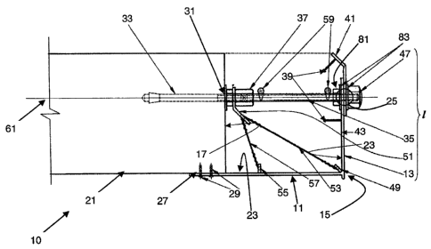
1
CA 02773765 2012-04-05
SUMMARY
[0005] A slab edge casing for finishing a slab edge is provided. The casing
comprises a face which defines a finished slab edge for an unfinished slab
edge;
and, a base which extends from the face. The base is connectable to one of a
slab
face that is adjacent the unfinished slab edge or is registerable with the
unfinished
slab edge. The face and base have respective inside surfaces that define a
form
into which concrete is poured and allowed to cure. In one embodiment, one of
the
face and base also comprise a reinforcing element mount for receiving a
reinforcing element that extends from the unfinished slab edge.
[0006] The slab edge may be a balcony edge.
[0007] A kit for finishing a slab edge is provided. The kit comprises a
casing,
which in turn comprises a face which defines a finished slab edge for an
unfinished slab edge and a base that extends from the face. The base may be
connectable to a slab face adjacent the unfinished slab edge or registerable
with
the unfinished slab edge. The face and base having respective inside surfaces
that
define a form into which concrete is poured and allowed to cure. The casing
also
comprises a brace mount positioned on one of the inside surfaces. In one
embodiment, one of the face and base comprises a reinforcing element mount for
receiving a reinforcing element extending from the unfinished slab edge.
[0008] The kit also comprises a reinforcing element that is securable to the
unfinished slab edge. The reinforcing element also comprises a brace mount.
The
kit also comprises a brace, extendable between the reinforcing element brace
mount and the casing brace mount, and connectable to the respective mounts.
[0009] In one embodiment, the reinforcing element, when secured to the
unfinished slab edge, extends from the unfinished slab edge to at least a
terminal
2
CA 02773765 2012-04-05
anchor point that corresponds to the finished slab edge.
[0010] The kit also comprises a brace, which is extendable between the
reinforcing element brace mount and the casing brace mount, and connectable to
the respective mounts.
[0011] A method for installing a slab edge is also provided. The method
comprises the steps of-
- securing a reinforcing element into the unfinished slab edge
[0012] - connecting a casing to the reinforcing element. The casing defines
the
finished slab edge and defines a form into which concrete is poured and
allowed
to cure.
[0013] - and, pouring the concrete into the form and allowing the concrete to
cure. The casing remaining in position after the concrete has cured.
LIST OF FIGURES
[0014] Figure 1(a) is a cross-sectional view of a finished slab edge in
accordance
with a first embodiment of the present invention;
[0015] Figure 1(b) is a cross-sectional view of a finished slab edge in
accordance
with a second embodiment of the present invention;
[0016] Figures 2(a) and 2(b) are cross-sectional views of alternate
embodiments
of a component of the finished slab edge of Figure 1(a);
[0017] Figure 3 is a front view of a component of a component of the finished
slab edge of Figure 1(a);
3
CA 02773765 2012-04-05
[0018] Figure 4 is a cross-sectional view of a finished slab edge in
accordance
with an alternate embodiment of the present invention;
[0019] Figure 5(a) is a plan view of a first corner portion of a finished slab
edge
in accordance with an embodiment of the present invention;
[0020] Figure 5(b) is a plan view of a first corner portion of a finished slab
edge
in accordance with an alternate embodiment of the present invention;
[0021] Figure 6(a) is a plan view of a second corner portion of a finished
slab
edge in accordance with an embodiment of the present invention;
[0022] Figure 6(b) is a plan view of a second corner portion of a finished
slab
edge in accordance with an alternate embodiment of the present invention;
[0023] Figure 7 is a flowchart illustrating the steps in a method according to
an
embodiment of the present invention;
[0024] Figure 8 is a flowchart illustrating additional steps in the method of
Figure
7;
[0025] Figure 9 is a flowchart illustrating additional steps in the method of
Figure
7;
[0026] Figure 10 is a cross-sectional view of a finished slab edge in
accordance
with an alternate embodiment of the present invention;
[0027] Figure 11(a) is a cross-sectional view of a one embodiment of a portion
of
the slab edge casing of the present invention; and
[0028] Figure 11(b) is a cross-sectional view of a first face portion of the
slab
edge casing of the present invention.
4
CA 02773765 2012-04-05
DETAILED DESCRIPTION
[0029] Referring to Figure 1(a), a cross-sectional view of a finished slab
edge 10
is illustrated in accordance with an embodiment of the present invention. In a
preferred embodiment, the slab edge 10 is a balcony edge. However, as will be
apparent to those skilled in the art, the slab edge 10 may be any known
concrete
slab, such as a parking garage pad.
[0030] The finished slab edge 10 comprises a slab edge casing 11, which in
turn
comprises a face 13, the outside surface of which defines a finished slab edge
15
for an unfinished slab edge 17. The casing 11 also comprises a base 19, which
extends from the casing face 13. The base 19 may be connectable to a slab face
21 adjacent the unfinished slab edge 17, as is illustrated in cross-section in
Figure
2(a). Alternately, the base 19 may register with the unfinished slab edge 17,
as is
illustrated in cross-section in Figure 2(b). A registration plate 63 may be
employed to aid in registering the base 19 with the unfinished slab edge 17.
The
plate 63 is preferably composed of the polymer, such as a glass fibre
reinforced
polymer or a GFRP as is known in the art. The plate 63 may be connected to the
base 19 and unfinished slab edge 17 by any suitable means known in the art.
[0031] Referring again to Figure 1(a), the face 13 and base 19 have respective
inside surfaces 23, which define a form into which concrete is poured and
allowed
to cure.
[0032] The casing 11 also preferably comprises a plurality of ribs 39, which
extend from the inside surfaces 23. The ribs 39, which are preferably formed
along with the casing I1 as a unitary structure, aid in securing the concrete
in
position within the form.
[0033] The finished slab edge 10 also comprises a reinforcing element 31,
which
CA 02773765 2012-04-05
is securable to the unfinished slab edge 17. The reinforcing element 31, when
secured to the unfinished slab edge 17, extends from the unfinished slab edge
17
to a terminal end, which ends at a point that corresponds to at least the
finished
slab edge 15. Preferably, the reinforcing element 31 is securable within a
hole
(not shown) that has been drilled into the unfinished slab edge 17 or by other
mechanical anchors known in the art.
[0034] In a first embodiment, the reinforcing element 31 comprises an anchor
bolt
33 that is securable within the hole; a rod 35, which extends from the anchor
bolt
33 to the terminal anchor point; and, a coupler 37, which connects the anchor
bolt
33 to the rod 35. Preferably, the rod 35 is a threaded rod, a portion of which
extends beyond the casing 11. The rod 35 is preferably composed of a steel,
such
as stainless steel. Alternately, the rod 35 is composed of a plastic. As will
be
apparent, the rod 35 may comprise any suitable material that is substantially
inert
to the environmental conditions of the installation.
[0035] Referring now to Figure 1(b), a cross-sectional view of the finished
slab
edge 10 in accordance with a second embodiment is illustrated. The reinforcing
element 31 may alternately comprise an extended rod 77, which extends from the
hole to the terminal anchor point. The extended rod 77 is a one-piece threaded
rod, a portion of which extends beyond the casing 11. The rod 77 is preferably
composed of a steel, such as stainless steel. Alternately, the rod 77 is
composed
of a plastic. As will be apparent, the rod may comprise any suitable material
that
is substantially inert to the environmental conditions of the installation.
The
extended rod 77 is preferably held in place within the hole with the use of a
suitable adhesive, such as an epoxy glue or cement or by suitable mechanical
anchors known in the art.
[0036] Referring to Figures 1(a) and 1(b), the extending portions of the
respective
6
CA 02773765 2012-04-05
rods 35,77 are configured to receive the lock 47. Preferably, the lock 47 is a
lock
nut or knob.
[0037] In a preferred embodiment, the lock 47 is also composed of a polymer
that
is resistant to the deteriorating effects of the environmental conditions of
the slab
installation. For example, the lock 47 may be composed to a suitable plastic.
[0038] Referring again to Figure 1(a), the casing 11 is preferably composed of
a
polymer, such as a glass-fibre reinforced polymer (GFRP) or a polyvinyl
chloride
(PVC), as is known in the art.
[0039] The face 13 of the casing 11 preferably has a length (1) corresponding
to
the height of the slab edge 10. In order to accommodate varying slab heights,
the
face 13 may be cut to the required height at any point during the installation
process. Alternately, and preferably, the casing face 13 comprises a first
face
portion 41 and a second face portion 43. The first and second portions (41,
43)
are positionable with respect to each other and securable to each other at a
position having a face length (1) corresponding to the slab height.
Preferably, the
first and second portions (41, 43) are slidably moveable with respect to each
other. For example, referring to Figure 3, a front view of the first and
second
portions (41, 43) is illustrated. The first portion 41 comprises at least one,
and
preferably a plurality, of guide channels 45, the positioning of which
corresponds
to the point at which the portion of the rod 35 (or rod 77 as is illustrated
in Figure
1(b)) of the reinforcing element 31 extends beyond the casing face 13. The
extending portion of the rod 35 is then engaged by a lock 47, thereby securing
the
first and second casing portions (41, 43) to each other. The lock 47
preferably
works in combination with a pair of washers 83 and nut 81. The guide channels
45 may be formed at any point during the manufacture and installation process.
For example, channel 45 may be pre-positioned during the manufacturing
process.
7
CA 02773765 2012-04-05
Alternately and preferably, the channel 45 is positioned and formed on-site
during
the installation process.
[0040] The face 13 also preferably comprises a reinforcing element mount 25.
Alternately, the base 19 comprises the reinforcing element mount 25, not
shown.
[0041] The reinforcing element mount 25 may comprise a passage extending
through the face 13, the rod 35 (or rod 77 as is illustrated in Figure 1(b))
passing
through the passage. The reinforcing element mount 25 may further comprise
related mounting accessories, such as the nut 81, washers 83 and lock 47. The
reinforcing element mount 25 may be formed at any point during the manufacture
and installation process. For example, the mount 25 may be pre-positioned
during
the manufacturing process. Alternately and preferably, the mount is positioned
and applied on-site during the installation process.
[0042] The slab edge casing 11 further comprises a base mount 27, which is
configured to receive securing means for securing the base 19 to the adjacent
slab
face 21. In a preferred embodiment, the base mount 27 is a passage extending
through the base 19 and the securing means is a screw 29 (preferably a self
tapping screw), which passes through the base mount 27 and into the slab face
21,
thereby securing the base 19 to the slab face 21. In installation, the
adjacent slab
face 21 is pre-treated prior to the base 19 being secured. For example, the
slab
face 21 may be sandblasted or otherwise abraded. The base 19 is then secured
with screws 29. Preferably, the base 19 is also glued to the adjacent slab
face 21.
[0043] Still referring to Figure 1(a), the slab edge casing 11 further
comprises a
brace mount 49, which is positioned on one of the inside surfaces 23 of the
casing
11. The reinforcing element 31 also further comprises an anchor brace mount
51,
such as a suspender. With the casing 11 and reinforcing element 31 being
8
CA 02773765 2012-04-05
configured with respective brace mounts (49, 51), the finished slab edge 10
additionally comprises a brace 53. The brace 53 extends between the
reinforcing
element brace mount 51 and the casing brace mount 49, and is connectable to
the
respective mounts 49, 51.
[0044] Preferably, the slab edge casing 11 comprises a second brace mount 55,
also positioned on one of the inside surfaces 23, but, separate and apart from
the
first brace mount 49. The second brace mount 55 is connectable to a second
brace
57, which extends from the reinforcing element 31. As will be apparent, the
casing brace mounts 49, 55 may alternately be configured to function as
additional casing ribs 39.
[0045] Still referring to Figure 1(a), the braces 53, 57 may be wire elements,
as is
illustrated. As such, the respective brace mounts 49, 51 and 55 are configured
to
receive the wire elements, which are then secured to the mounts 49, 51 and 55.
The wire elements may be secured to the mounts 49, 51 and 55 by any known
means.
[0046] Referring to Figure 4, an alternate embodiment of the brace 53 is
illustrated. In this alternate embodiment, the brace 53 is a bar element,
which
may be composed of light gauge steel or a glass fibre reinforced polymer. As
will
be apparent, the brace 53 may be comprised of any material that suits the slab
edge's particular installation environment.
[0047] In this alternate embodiment, the mounts 49, 51 are configured to
receive
the bar element. For example, as is illustrated in Figure 4, the brace 53 may
be
shaped to engage the inside surface 23, thereby permitting the brace 53 to be
secured directly to the inside surface 23. In this particular embodiment, the
casing brace mount 49 is may be a rivet (or similar securing means) which
secures
9
CA 02773765 2012-04-05
the brace 53 to the casing 11. The opposite end of the brace 53 may be secured
directly to the reinforcing element 31. In the embodiment illustrated, the
brace 53
is secured in place between the anchor bolt 33 and the coupler 37. The brace
53
may be secured to the reinforcing element 31 and the casing 11 by any suitable
means known to those skilled in the art.
[0048] The casing 11, as has been described above, is preferably composed of a
FRP (Fiber Reinforced Polymer). In an alternate embodiment, the casing 11 may
be composed of a PVC (polyvinyl chloride). The thickness of the PVC composed
casing 11 compared to that of the FRP composed casing 11 will preferably be
adjusted (increased) to compensate to PVC's relatively lower modulus of
elasticity. In either case, respective thicknesses of the FRP and PVC casings
11
will be selected, taking in to account the materials' respective modulus of
elasticity, to minimise any deflection of the casing 11 caused by the
concrete.
Deflection is kept at a minimum in order to maintain the visual presentation
of the
finished slab edge 15.
[0049] PVC, as a material for casing 11 construction, offers a number of
advantages over FRP. One advantage is that PVC can be welded on site (in
addition to being glued or cemented, as may also be required). Welding permits
on site customization of the casing 11. It also reduces the number of welding
plates that are required to connect casing pieces together, as in the corner
portion
of the finished slab edge, for example. An additional advantage of using PVC
is
that the face 13 and base 19 may be formed separately and welded on site to
form
the casing 11.
[0050] An embodiment of the present invention may alternately be characterized
as a kit for finishing as unfinished slab edge. The kit comprises the casing
11, the
CA 02773765 2012-04-05
reinforcing element 31 and a brace 53, as defined above, including the
alternate
embodiments. Preferably, the kit comprises a plurality of reinforcing elements
31
and a plurality of braces 53. For example, the kit may comprise an equal
number
of reinforcing elements 31 and braces 53.
[0051] Referring to Figure 5(a), a corner portion of a finished slab edge 10
is
illustrated in plan view. A slab edge corner casing 71 for the corner portion
is
illustrated. In the illustrated embodiment, the corner portion comprises two
adjacent unfinished slab edges 17, which are positioned orthogonally to each
other. Any suitable non-orthogonal positioning may be employed, as may be
dictated by the slab structure.
[0052] The corner casing 71 comprises adjacent faces 13, which define the
finished slab edge 10. From each face 13, a respective base 19 extends. The
bases 19 are either connectable to a slab face 21 adjacent the unfinished slab
edge
17; or, registerable with the unfinished slab edge 17. The faces 13 and bases
19
have respective inside surfaces which define a form unto which concrete is
poured
and allowed to cure. Each face 13, base 19 pairing also comprises a
reinforcing
element mount 25 for receiving a respective reinforcing element 31 that
extends
from the unfinished slab edge 17. As stated previously, the casing 13 may
further
comprise base mounts 27 (not shown) for receiving securing means, such as self-
tapping screws 29.
[0053] Also, as stated previously, the corner casing 71 may further comprise a
brace mount 49 positioned on one of the inside surfaces 23 (not shown). The
brace mount 49 is connectable to a brace 53 extending from the reinforcing
element 31 (not shown). The corner casing 71 may additionally comprise a
second brace mount 55 (not shown). As will be apparent, the corner casing 71
is
comprised similarly to the casing 11. As such, it may comprise:
11
CA 02773765 2012-04-05
= a plurality of ribs 39 extending from the inside surfaces 23 (not shown);
and,
= a polymer composition, preferably a glass-fibre reinforced polymer.
[0054] As with the casing 11, the face 13 of the corner casing 71 has a length
corresponding to the slab height. Alternatively, the face 13 of the corner
casing
71 may comprise the first face portion 41 and second face portion 43, as
described
above.
[0055] Referring to Figure 5(b), the corner portion of Figure 5(a) is
illustrated
with the reinforcing element 31 comprising the rod 77. This corner portion is
identical to that of Figure 5(a) in all other respects.
[0056] Referring to Figure 6(a), a corner of a finished slab edge 10 is
illustrated
according to an alternate embodiment. In this embodiment, the casings 11 are
cut
at an angle A, which is determined by the particular installation
requirements.
[0057] Referring to Figure 6(b), the corner portion of Figure 6(a) is
illustrated
with the reinforcing element 31 comprising the rod 77. This corner portion is
identical to that of Figure 6(a) in all other respects.
[0058] Referring to Figures 5 and 6, means for connecting adjacent casings 11
(or
11 and 71) is illustrated. The adjacent casings 11 (or 11 and 71) are placed
side
by side. A coupling plate 73 is the positioned at the common border of the
adjacent casings 11 (or 11 and 71). The plate 73 is then secured to the
casings 11
(or 11 and 71), as is illustrated. Preferably, the connection comprises a base
coupling plate and a face coupling plate. The plates 73 preferably are
composed
of a fibre reinforced polymer.
[0059] Referring to Figure 1(a), the finished slab edge 10 may further
comprise
12
CA 02773765 2012-04-05
reinforcing bars 59, which are positionable between the finished and
unfinished
slab edges 15,17 in an orientation orthogonal to a longitudinal axis 61 of the
reinforcing element 31. The reinforcing bars may be composed of any suitable
corrosion resistant material, such as any one of fibre reinforced polymer and
steel
(such as stainless steel).
[0060] Referring to Figure 7, a flow chart illustrating the steps in a method
in
accordance with a preferred embodiment is provided. The method provided is for
finishing an unfinished slab edge. The method comprises the steps of:
(a) securing a reinforcing element 31 into the unfinished slab edge 17. (Step
100) The reinforcing element 31 extends from the unfinished slab edge 17 to a
terminal end that extends to a point corresponding to the installed position
of the
finished slab edge 10;
(b) connecting a casing 11 to the reinforcing element 31 at the terminal end.
(Step 200) The casing defines the finished slab edge 10 and defines a form
into
which concrete is poured and allowed to cure; and,
(c) pouring the concrete into the form and allowing the concrete to cure.
(Step
300) The casing 11 remains in position after the concrete has cured.
[0061] Step (a) may further comprise any one or a combination of the steps of.
(a) cutting the slab to remove an original deteriorated slab edge and expose
the unfinished slab edge 17. (Step 100 (a)). [As will be apparent, any
suitable
cutting tool, such as a circular or chain saw for concrete, may be employed.
The
use of the cutting tool contrasts with traditional methods, which involve the
use of
percussion or impact tools (commonly referred to as jack hammers) of varying
sizes, which are used to remove the concrete and preserve the underlying
13
CA 02773765 2012-04-05
reinforcing bars.]
(b) drilling a plurality of holes into an unfinished slab edge 17 (Step 100
(b));
and,
(c) securing a reinforcing element 31 into each of the holes. (Step 100 (c)).
[The number of holes drilled, and the drilling depth of the holes are
determined by
the particular installation requirements. The reinforcing element 31 may be
secured into its hole by any one or a combination of the action of an anchor
bolt
portion 33 of the reinforcing element 31 and the use of a suitable adhesive or
mechanical anchoring means known in the art.
[0062] Step (b) may further comprise any one or a combination of the steps of:
(a) securing a lock to a portion of the terminal end that extends beyond the
finished edge 15. (Step 200 (a));
(b) connecting the casing 11 to a face 21 adjacent the unfinished slab edge.
(Step 200 (b));
(c) positioning reinforcing bars 59 between the finished and unfinished slab
edges 15,17 in an orientation orthogonal to a longitudinal axis 61 of the
reinforcing element 31. (Step 200 (c));
(d) connecting a brace 53 to a casing brace mount 49 and a reinforcing
element brace mount 51. (Step 200 (d)); and,
(e) connecting a second brace 57 to the reinforcing element brace mount 51
and a second casing brace mount 55. (Step 200 (e)).
[0063] An alternative embodiment of the slab edge casing is shown in Figures
10-
14
CA 02773765 2012-04-05
11 in which the slab edge casing is shown generally at numeral 11. Figure 10
shows a finished slab edge 10 comprising an alternate embodiment of the slab
edge casing 11. The slab edge casing 11 includes a face 13, the outside edge
of
which defines a finished slab edge 15 for an unfinished slab edge 17. The
casing
11 also comprises a base 19, which extends from the casing face 13 and is
connectable to, or registrable with, a slab face 21 adjacent the unfinished
slab
edge 17, as described in the alternate embodiments discussed above.
[0064] As described above, each of the face 13 and the base 19 have respective
inside surfaces 23, which define a form into which concrete is poured and
allowed
to cure.
[0065] The finished slab edge includes a reinforcing element 31, which is
securable to the unfinished slab edge 17. The reinforcing element 31, when
secured to the unfinished slab edge 17, extends from the unfinished slab edge
17
to a terminal end 32 located within the finished slab edge 10. The terminal
end 32
is spaced from the inside surface 23 of the face 13. To secure the reinforcing
element 31 to the unfinished slab edge 17, and within the slab face 21, the
reinforcing element may include an anchor bolt 33, as shown in Figure 1(a)
above
or an extended rod 77, as shown in Figure 1(b).
[0066] The reinforcing element 31 includes at least one reinforcing brace
mount
60 to which one or more braces 53 are connected. The reinforcing brace mount
60
may be located directly on the reinforcing element 31, or it may be positioned
on
a reinforcing bar 59 positioned between the finished and unfinished slab edges
15,
17. The reinforcing bar 59 and its location is described above.
[0067] The base 19 of the casing 11 may be connected to the adjacent slab face
21 as described above. Alternatively, the base 19 may be adhered to the slab
face
CA 02773765 2012-04-05
21, using a suitable adhesive product, as shown generally at numeral 26, and
additional securing means, such as a screw 29 may be used.
[0068] Located on the inside surface 23 of each of the base 19 and the face 13
of
the casing 11 are a series of brace mounts, or ribs, 56 that extend inwardly
from
the inside surface(s) 23. The brace mounts 56 may be straight or curved and
include a bulbous end portion 58 which aids in securing the concrete in
position
within the form. In addition, the end portion 58 of each brace mount 56 is
configured to connect to a brace 53 extending between the brace mount 56 and
the
reinforcing brace mounts 60, 60a.
[0069] As can be seen in Figure 10, the illustrated embodiment includes five
braces 53, each extending between one of the two reinforcing brace mounts 60
and 60a, located on the reinforcing element 31, and one of the brace mounts
56. It
will be understood that the casing 11 is not limited to being used with only
five
braces. The number of braces 53 to be used will depend on the amount of
reinforcement required for the final product. The braces 53 may be wire
elements,
as discussed above, that may be secured to the mounts 56, 60 and 60a by any
known means. The brace 53 may also be a bar element, as discussed above.
Depending on the depth of the casing 11, brace mounts may only be located on
the surface 23 of the face 13.
[0070] As can be seen in Figures 10 and 11, in the illustrated embodiment the
casing 11 includes a series of brace mounts 56 located along the inside face
23 of
the face 13 and an additional two brace mounts 56 located along the inside
surface
23 of the base 19. The brace mount 56 that is located adjacent the unfinished
slab
edge 17 is substantially vertical relative to the base 19 so that it may lie
substantially flush with the unfinished slab edge 17. The brace mount 56
adjacent
the unfinished slab edge is intended for alignment rather than support and
16
CA 02773765 2012-04-05
accordingly is optional. The remaining brace mounts 56 positioned along the
insides surface 23 of the face 13 are preferably substantially curved which
provides for additional reinforcement when the concrete is poured into the
casing
11.
[0071 ] Turning to Figures 11(a) and (b) the casing 11 is shown in isolation.
The
casing face 13 includes a first portion 62, shown in Figure 11(a) and a second
portion 64, shown in Figure 11(b). As seen in Figure 11(b) the second portion
64
includes a channel 66 that is sized to receive the end 68 of the first portion
62.
The first portion 62 is operable to slidably move within channel 66 and allows
for
adjustment of the height of the casing face 13 by way of the relative
positioning
of the end 68 of the first portion 62 within the channel 66. The connection of
the
first and second portions 62, 64 may be by any means known in the art
including
friction.
[0072] The top part of the first portion 62 includes a top ledge 70 that
extends
substantially perpendicular to the second portion 64 and includes a curved end
portion 72 that is configured to connect to a brace 53, as shown in Figure 10.
Included in the top ledge 70 and the adjacent brace mount 56 are apertures 74.
The apertures 74 provide holes for trapped air release during the pouring of
the
concrete which prevents any air holes from forming in the top concrete layer
of
the finished slab. While only two apertures are shown in the embodiment
illustrated in Figure 11(b) it will be understood that the number of apertures
may
vary depending on the end use of the casing 1 I and the size of the concrete
form
to be made.
[0073] The lower part of the second portion 64 includes a drip edge 76 which
extends beyond the base 19 to prevent water from dripping under the casing 11.
17
CA 02773765 2012-04-05
[0074] The method for finishing an unfinished slab edge will now be described
with reference to the embodiment shown in Figures 10-11. The method comprises
the steps of.
(a) securing a reinforcing element 31 into the unfinished slab edge 17;
(b) connecting a casing 11 to the reinforcing element 31, the casing defining
the finished slab edge 15 and defines a form into which concrete is poured and
allowed to cure; and,
(c) pouring the concrete into the form and allowing the concrete to cure, the
casing 11 remaining in position after the concrete has cured.
[0075] Step (a) may further comprise any one or a combination of the steps of.
(a) cutting the slab to remove an original deteriorated slab edge and expose
the unfinished slab edge 17.
(b) drilling a plurality of holes into an unfinished slab edge 17; and,
(c) securing a reinforcing element 31 into each of the holes.
[0076] Step (b) may further comprise any one or a combination of the steps of.
(a) connecting the casing 11 to a face 21 adjacent the unfinished slab edge;
(b) positioning reinforcing bars between the finished and unfinished slab
edges 15,17 in an orientation generally orthogonal to a longitudinal axis 61
of the
reinforcing element 31; and
(c) connecting one or more braces 53 to one or more casing brace mounts 56
and one or more reinforcing element brace mounts 60, 60a.
18
CA 02773765 2012-04-05
[0077] The above description is intended in an illustrative rather than
restrictive
sense. Variations may be apparent to those skilled in the art without
departing
from the spirit and scope of the invention as defined by the claims set out
below.
19