Note: Descriptions are shown in the official language in which they were submitted.
CA 02773844 2012-03-09
WO 2011/039226 PCT/EP2010/064419
1
Description
Method for assembling a drug delivery device, assembly for a drug delivery
device and
piston rod for a drug delivery device
The present invention relates to a method for assembling a drug delivery
device,
particularly for securing a cartridge to a body of a drug delivery device. The
invention
further relates to a drug delivery device, an assembly for a drug delivery
device and a
piston rod contained in an assembly for a drug delivery device.
Drug delivery devices are generally known to be used for the administration of
medicinal
products, for example insulin or heparin, but also for other medicinal
products for self-
administration by a patient. Often, drug delivery devices are pen-type
injectors which
dispense a pre-set dose of a fluid medicinal product.
Prior to the first use of the drug delivery device, the drug delivery device
usually has to
be primed. During a priming-step gaps may be closed which are contained in the
drug
delivery device between components, particularly between a piston rod and a
cartridge
bung, which are involved in the mechanism for dispense of the fluid medicinal
product.
These gaps may be a consequence of the tolerances associated with all the
assembled
parts which may occur through the manufacturing of the device and the
requirement not
to pre-load the bung axially in the assembled device. However, users who are
not
familiar with such pen-type injectors may fail to or incorrectly prime the
drug delivery
device before dispensing the first dose and may inject the prime fluid of an
incorrect
volume of the medicinal product delivered in the first dose.
It is an object of the present disclosure to provide an assembly for the use
in a drug
delivery device which is more user friendly and, particularly, helps to
improve the
accuracy of the first dispensed dose of the fluid medicinal product.
This object may be achieved by the subject matter of the independent claims.
Further
features are the subject matter of dependent claims as well as the
description.
CA 02773844 2012-03-09
WO 2011/039226 PCT/EP2010/064419
2
According to a first aspect, a method for assembling a drug delivery device is
provided.
The method involves providing a cartridge retaining a bung and holding a drug
as well
as providing a body retaining a piston rod (step A). The body has a distal end
and a
proximal end which are spaced apart in the direction of an axis. The piston
rod retained
in the body is plastically deformable and at least a part of this plastically
deformable
piston rod is manufactured from a plastically deformable material. In a second
step
(step B), a force is applied on the piston rod in a state wherein at least a
part of the
piston rod or at least a part of the area being manufactured from a
plastically
deformable material allows plastic deformation. Upon applying the force on the
piston
rod, the piston rod is plastically deformed and an element of the piston rod
abuts the
bung. In a further step (step C), conditions are applied in order to bring the
plastically
deformed piston rod into an altered state wherein no further plastic
deformation takes
place. Before, during or after the step of plastic deformation, the cartridge
is secured to
the body (step D).
According to the present invention, a component is plastically deformable if
this
component may be deformed upon application of a force, particularly
irreversibly
deformed. Furthermore, the piston rod or the plastically deformable part or
element of
the piston rod undergoes plastic deformation without fracture or damage of the
operational capability of the piston rod. After having plastically deformed
the piston rod,
conditions are applied which do not allow further plastic deformation,
particularly, plastic
deformation which would have occurred under the conditions of step B (i.e.
occurred
upon application of a force on the piston rod). Usually, these conditions do
not involve
fixing the plastically deformed piston rod to a further part of the drug
delivery device or
fixing the plastically deformed part and a further part of a multi-part piston
rod to each
other. Usually the conditions involve altering the physical state of matter or
the chemical
state of matter of at least a part of the material of the piston rod or both,
the physical
and the chemical state of matter. Additionally, the plastic deformation
according to the
present invention usually does not cause an increase of stresses or loads
within the
piston rod and usually also not an increase of stresses or loads within a one-
piece or of
a multi-part piston rod or a section thereof.
This method of assembling a drug delivery device according to the present
invention
solves the problem of risks associated with the prime set-up step by removing
the need
CA 02773844 2012-03-09
WO 2011/039226 PCT/EP2010/064419
3
for the user to prime the pen injector before use. Therefore, the user does
not have to
prime the device and, therefore, will not accidentally inject prime fluid.
The method for assembling the drug delivery device according to the present
invention
allows adjusting the shape (particularly the axial extension) of the piston
rod during
assembly, preferably during final assembly after the medicament cartridge has
been
fitted so that an element of the piston rod abuts the bung retained in the
cartridge. Due
to the adjustment of the length of the piston rod, tolerances between
components being
responsible for disposing a dose of drug, particularly tolerances between the
piston rod
and the bung, are removed and the need for a "priming" operation to be
undertaken by
users prior to delivering the first dose of medicament is eliminated.
Usually, the piston rod provided in step A is intentionally too long to take
up the
maximum allowable gap between the components being involved in the mechanism
to
deliver a dose of drug, particularly the gap between the piston rod and the
bung. By
applying the force and thereby plastically deforming the piston rod, the
distance
extending between the distal end and the proximal end of the piston rod is
adjusted in
order to eliminate the gaps between aforesaid components.
Usually, the applied force results in a compression of the piston rod in
longitudinal
direction; however, also an expansion of the plastically deformable piston rod
may be
carried out at first followed by a compression as described before. If at
first an
expansion takes place, the length of the piston rod does not have to be
intentionally too
long to take up the maximum allowable gap between the aforesaid components of
the
assembly.
In an embodiment, the drive mechanism comprised in the body of the drug
delivery
device is brought into a position which resembles the situation during
dispense of a
dose of the drug or being identical with the situation during dispense of a
dose of the
drug prior to step B, particularly the situation at the end of the dispense
step. This gives
rise to correctly take up tolerances of the drive mechanism (or more general
tolerances
or gaps between the components being involved in the mechanism to deliver a
dose)
during step B. Further, a drive mechanism being in this situation would
simulate forces
that would be seen during dispense of a dose.
CA 02773844 2012-03-09
WO 2011/039226 PCT/EP2010/064419
4
In an embodiment, the applied force of step B results from a movement of the
piston rod
in distal direction or a movement of a component being fixed to the piston rod
in distal
direction (i.e. a movement which also causes movement of the piston rod in
distal
direction), or a movement of the cartridge in proximal direction, or a
movement of a
component being fixed to the cartridge (i.e. a component which also causes
movement
of the cartridge) in proximal direction.
By carrying out the method according to this embodiment, step B is easily
carried out
when two main parts of the housing of the drug delivery device, the body and a
cartridge holder retaining the cartridge, are assembled. However, the method
according
to this embodiment may also be carried out in a separate step, the assembly of
body
and cartridge holder taking place later on.
In a further embodiment, between steps A and B of the method of the present
invention,
a step E is carried out: in step E, the plastically deformable material is
brought into a
plastically deformable state of matter by heating. More generally speaking,
the step of
this embodiment involves the change of a state of matter where no plastic
deformation
of the piston rod is possible to a state of matter where plastic deformation
is possible.
However, embodiments starting from a state where no plastic deformation is
possible
usually involve raising the temperature in order to bring the piston rod into
the state of
matter where plastic deformation is possible.
Usually, the plastically deformable material is heated to a temperature above
the glass
transition temperature of the material, particularly of only heating the area
to be
plastically deformed above the glass transition temperature of the material of
this area.
Further, the temperature is usually not raised above the melting temperature
of the
respective material (i.e. the plastically deformable material).
The heating of the plastically deformable material may be effected by direct
heating (e.g.
a heated nest on the assembly line where the drug delivery device is assembled
or by a
concentrated light source which allows precisely determining the area which
should
undergo plastic deformation) or by indirect heating (e.g. by induction or by a
chemical
reaction which involves the release of heat).
CA 02773844 2012-03-09
WO 2011/039226 PCT/EP2010/064419
If at standard conditions the piston rod or the area to be plastically
deformed is already
in a plastically deformable state of matter, no heating is necessary (i.e.
step E may be
omitted). This may be the case, if in step C the plastically deformable
material is
5 brought into a state of matter where no plastic deformation takes place for
example by a
chemical reaction.
In a further embodiment, the method according to the invention involves
providing a
piston rod which is at least partially manufactured from a polymer,
particularly a
thermoplastic polymer. Therefore, the plastically deformable material of step
A may
comprise a thermoplastic polymer or consist of a thermoplastic polymer. The
material
may, for example, comprise PVC or PMMA. By using a thermoplastic polymer, the
piston rod provided in step A may easily be obtained by injection molding.
In a further embodiment, the altered state of matter of step C of the method
of the
present invention is obtained by cooling or by effecting a chemical reaction
of the
plastically deformable material.
Upon cooling, particularly cooling below the glass transition temperature of
the
plastically deformable material, the state of matter changes and the piston
rod is not
plastically deformable any longer. If a step E (during which the temperature
of the
plastically deformable material had been raised) is carried out, the cooling
step involves
changing the state back to the original state being present before the heating
step E
was carried out.
On the other hand, an altered state of matter may also be effected by a
chemical
reaction. Particularly, a chemical reaction may involve cross-linking of
polymer chains of
an oligomeric or polymeric material contained in the plastically deformable
material or a
polymerization of the plastically deformable material (e.g. a polymerization
of monomers,
oligomers or monomeric groups contained in a polymer). This chemical reaction
can, for
example, be started by radiation (for example UV-light) or by raising the
temperature
(causing, for example, an addition polymerization or a radical polymerization
using e.g.
a temperature-sensitive starter). Additionally, the chemical reaction may
involve a
reaction as known from two component adhesives, particularly a reaction of a
binder
CA 02773844 2012-03-09
WO 2011/039226 PCT/EP2010/064419
6
and a curing agent. Preferably, the binder imparts dimensional stability (at
least
dimensional stability to a certain extent) of the piston rod or the
plastically deformable
material already in the state of matter before carrying out the chemical
reaction. As far
as cross-linking is concerned, particularly a change from a thermoplastic
polymer to a
duroplastic polymer may be effected by the chemical reaction.
In order to allow the production of a plastically deformable piston rod to be
provided in
step A which is already in the state where plastic deformation is possible,
the material to
be used for this piston rod usually needs to be dimensionally stable and
should only be
intentionally deformed during the deformation step B but not by other steps
being
involved in the assembly of the drug delivery device. Therefore, materials to
be
polymerized will usually contain oligomers, polymers or other components
imparting an
increased dimensional or mechanical stability (for example fillers).
In a further embodiment, the piston rod provided in step A of the present
invention
comprises an inductively heatable element or material.
Using a piston rod comprising an inductively heatable material (or compound)
allows
precisely predetermining the area which should undergo plastic deformation.
Upon
inductively heating a piston rod comprising an inductively heatable material,
only the
area comprising this material changes its state of matter into a state where
plastic
deformation may take place. Therefore, by adding inductively heatable material
to the
material of the piston rod, particularly to a piston rod made of thermoplastic
material, a
predetermined area of weakness may easily be defined.
The inductively heatable material may particularly be a ferro-magnetic
material, for
example in the form of iron particles. The inductively heatable material may
be just
mixed with the main material of the piston rod; it may also be chemically
bonded to the
main material of the piston rod, particularly the thermoplastic material, for
example by
using Fe304 particles with a chemically modified surface (giving rise to a
more
homogenous distribution of the inductively heatable material).
In a further embodiment, the piston rod comprises at least two elements, at
least the
first element comprising the plastically deformable material and at least a
part of the
CA 02773844 2012-03-09
WO 2011/039226 PCT/EP2010/064419
7
second element being manufactured from an inductively heatable material.
Usually, the
first and the second element are abutting. Therefore, the second element may
consist of
an inductively heatable material; it also may comprise the inductively
heatable material,
for example the surface of the second element may completely or partially be
covered
by an inductively heatable material. However, any part of the second element
may
contain the inductively heatable material as long as the remaining part of the
second
element is manufactured from a material conducting heat. As mentioned before,
the
inductively heatable material is usually a ferro-magnetic material, and may be
for
example iron.
At least one of aforesaid first and second element in the assembled drug
delivery device
usually abuts the bung retained in the cartridge. However, also a further
element
abutting the bung may be present between the bung and the first and the second
element.
The second element or also a further element of the piston rod may, for
example, be a
bearing being arranged between the main part of the piston rod and the bung,
the
bearing being particularly responsible for a transformation of any movement of
the main
part of the piston rod into a movement of the bung in distal direction only.
However, the second element may also be an element of any conceivable shape
being
comprised in the piston rod (for example with the shape of a ball); the only
duty of such
a second element being to transfer heat to the predetermined area of weakness
comprised in the piston rod or in other words to the area comprising the
plastically
deformable material.
Upon inductively heating the second element, the state of matter of the
plastically
deformable material of the first element of the piston rod changes and
thereby, the
material is brought into a state of matter which allows carrying out step B.
According to a second aspect of the present invention, a further method for
assembling
a drug delivery device is provided.
CA 02773844 2012-03-09
WO 2011/039226 PCT/EP2010/064419
8
In the method according to this aspect, a component is provided which defines
the
distance between the proximal face of the bung retained in the cartridge which
holds a
drug and the proximal end of the piston rod retained in the body (wherein the
body has
a distal end and a proximal end) in step A'. In steps B' and C', the cartridge
and the
distance defining component are engaged and the cartridge is arranged in its
most
distal position with respect to the distance defining the component.
Subsequently, the
distance between the proximal face of the bung and the proximal end of the
distance
defining component is determined. In step D', the gaps between the proximal
face of the
bung and the distal end of the piston rod is calculated from the distance
determined in
step U. Subsequently, in step E', the length of the piston rod is adjusted to
the length
derived by the calculation obtained in step U. Finally, the cartridge
comprising the bung
is secured to the body comprising the piston rod (step F').
Like the method according to the first aspect, the method according to the
second
aspect removes tolerances from the mechanism and eliminates the need for a
"priming"
operation to be undertaken by users prior to delivering the first dose of
medicament.
The adjusting of the length of the piston rod may involve any adjusting method
or step
being described for the method according to the first aspect, particularly by
adjusting the
length of the piston rod by plastic deformation. However, also other adjusting
methods
like cutting (e.g. laser cutting) may be applied.
According to an embodiment, the distance defining component of this aspect may
be a
cartridge holder or the piston rod.
If there is also tolerance between the proximal end of the cartridge holder
being used as
distance defining component and the proximal end of the piston rod, also the
distance
between the piston rod in its most proximal position with respect to the
cartridge holder
is usually taken into account in the calculation step U.
According to a third aspect, a piston rod contained in an assembly of a drug
delivery
device is provided. The piston rod has a distal end and a proximal end which
are
spaced apart in the direction of an axis and comprises a predetermined area of
CA 02773844 2012-03-09
WO 2011/039226 PCT/EP2010/064419
9
weakness. This piston rod is deformable upon application of a force,
particularly in the
direction of the axis with respect to the piston rod.
The piston rod according to the third aspect allows easy adjustment of the
length of the
piston rod, particularly if the material comprised in the predetermined area
of weakness
is in a plastically deformable state of matter.
In particular, the piston rod may be constructed as described before.
Particularly, the
predetermined area of weakness preferably is an area which comprises or
consists of
plastically deformable material. Further, the predetermined area of weakness
is usually
not designed to allow mechanical engagement of two parts of the piston rod
during step
B, particularly not for connecting the two parts in a form-fitting way.
In an embodiment, the predetermined area of weakness (or in general the piston
rod)
comprises one or more openings or being more general one or more recesses
being
present in the piston rod. Therefore, the predetermined area of weakness
usually
comprises areas which are designed for changing their shape upon application
of the
force in axial direction. Particularly, the recesses or openings may have a
shape which
allows an easier deformation by a force applied in the direction of the axis
than a force
applied, for example, perpendicularly to this axis. For example, the surface
of the
predetermined area of weakness may comprise one or more recesses in the shape
of a
fold, for example a circumferential fold with respect to aforesaid axis.
Openings may
have a shape where the distance of the opening in the direction of the axis is
longer
than the distance in the direction perpendicular to the axis. Upon application
of the force,
the size of the opening or the recess may decrease, for example due to the
deformation
(i.e. the opening takes up deformed material).
Usually, the method involving the adjustment of the length of the piston rod
is
independent of the main mechanism used to set and dispense drug doses with the
drug
delivery device. Therefore, the form of the piston rod used for this invention
is arbitrary
as long as the piston rod comprises a plastically deformable area. Further,
the area of
the piston rod to be plastically deformed usually does not overlap with areas
of the
piston rod being responsible for the main mechanism for setting and dispensing
drug
doses (and does for example not overlap with parts of the piston rod
interacting with
CA 02773844 2012-03-09
WO 2011/039226 PCT/EP2010/064419
components of the drive mechanism). Therefore, the plastically deformed area
usually
does not comprise parts of the piston rod being necessary for the mechanism of
setting
and dispensing drug doses.
5 According to a fourth aspect, an assembly for a drug delivery device is
provided. The
assembly comprises a body retaining a piston rod, particularly the piston rod
as
described before, and a cartridge retaining a bung. The cartridge is secured
to the body
and an element (i.e. the part at the distal end) of the piston rod abuts the
proximal face
of the bung. The piston rod comprises a plastically deformed element
comprising a
10 plastically deformed area. At least a part of said plastically deformed
element is
obtained from a plastically deformable material.
The element of the piston rod comprising the plastically deformed area may be
the
element of the piston rod abutting the bung.
Usually, the plastically deformed area is characterized by features derived
from a
compression of an predetermined area of weakness. Preferably, the assembly
according to this aspect is obtained by one of the methods described before.
According to a fifth aspect, a drug delivery device comprising an assembly as
described
before is provided.
The drug delivery device may be an injection device. The drug delivery device
may be a
pen-type device, e.g. a pen-type injector which may be an injector for single-
use or
multiple-use. The cartridge may hold a plurality of doses of a drug.
Preferably, the drug
comprises a liquid medication, such as a long-acting or short-acting insulin,
GLP-1,
heparin or growth hormones. The drug delivery device may be designed such that
it
may accommodate cartridges of different sizes. Additionally or alternatively,
the drug
delivery device may be designed such that it may accommodate cartridges of
different
shapes.
The cartridge/cartridge holder may be permanently secured to the body by
connection
means. For example, the connection means may be joined by welding.
Additionally or
alternatively, the connection may comprise use of a separate connecting
material such
CA 02773844 2012-03-09
WO 2011/039226 PCT/EP2010/064419
11
as an adhesive. The cartridge holder may be reversibly or irreversibly secured
to the
body, alternatively, the cartridge may be directly secured to the body and the
use of a
cartridge holder may be redundant.
The term "drug", as used herein, preferably means a pharmaceutical formulation
containing at least one pharmaceutically active compound,
wherein in one embodiment the pharmaceutically active compound has a molecular
weight up to 1500 Da and/or is a peptide, a proteine, a polysaccharide, a
vaccine, a
DNA, a RNA, an enzyme, an antibody, a hormone or an oligonucleotide, or a
mixture of
the above-mentioned pharmaceutically active compound,
wherein in a further embodiment the pharmaceutically active compound is useful
for the
treatment and/or prophylaxis of diabetes mellitus or complications associated
with
diabetes mellitus such as diabetic retinopathy, thromboembolism disorders such
as
deep vein or pulmonary thromboembolism, acute coronary syndrome (ACS), angina,
myocardial infarction, cancer, macular degeneration, inflammation, hay fever,
atherosclerosis and/or rheumatoid arthritis,
wherein in a further embodiment the pharmaceutically active compound comprises
at
least one peptide for the treatment and/or prophylaxis of diabetes mellitus or
complications associated with diabetes mellitus such as diabetic retinopathy,
wherein in a further embodiment the pharmaceutically active compound comprises
at
least one human insulin or a human insulin analogue or derivative, glucagon-
like
peptide (GLP-1) or an analogue or derivative thereof, or exedin-3 or exedin-4
or an
analogue or derivative of exedin-3 or exedin-4.
Insulin analogues are for example Gly(A21), Arg(B31), Arg(B32) human insulin;
Lys(B3),
Glu(B29) human insulin; Lys(B28), Pro(B29) human insulin; Asp(B28) human
insulin;
human insulin, wherein proline in position B28 is replaced by Asp, Lys, Leu,
Val or Ala
and wherein in position B29 Lys may be replaced by Pro; Ala(B26) human
insulin;
Des(B28-B30) human insulin; Des(B27) human insulin and Des(B30) human insulin.
CA 02773844 2012-03-09
WO 2011/039226 PCT/EP2010/064419
12
Insulin derivates are for example B29-N-myristoyl-des(B30) human insulin; B29-
N-
palmitoyl-des(B30) human insulin; B29-N-myristoyl human insulin; B29-N-
palmitoyl
human insulin; B28-N-myristoyl LysB28ProB29 human insulin; B28-N-palmitoyl-
LysB28ProB29 human insulin; B30-N-myristoyl-ThrB29LysB30 human insulin; B30-N-
palmitoyl- ThrB29LysB30 human insulin; B29-N-(N-palmitoyl-Y-glutamyl)-des(B30)
human insulin; B29-N-(N-lithocholyl-Y-glutamyl)-des(B30) human insulin; B29-N-
(w-
carboxyheptadecanoyl)-des(B30) human insulin and B29-N-(w-
carboxyheptadecanoyl)
human insulin.
Exendin-4 for example means Exendin-4(1-39), a peptide of the sequence H-His-
Gly-
Glu-Gly-Thr-Phe-Thr-Ser-Asp-Leu-Ser-Lys-Gln-Met-Glu-Glu-Glu-Ala-Val-Arg-Leu-
Phe-
Ile-Glu-Trp-Leu-Lys-Asn-Gly-Gly-Pro-Ser-Ser-Gly-Ala-Pro-Pro-Pro-Ser-NH2.
Exendin-4 derivatives are for example selected from the following list of
compounds:
H-(Lys)4-des Pro36, des Pro37 Exendin-4(1-39)-NH2,
H-(Lys)5-des Pro36, des Pro37 Exendin-4(1-39)-NH2,
des Pro36 [Asp28] Exendin-4(1-39),
des Pro36 [IsoAsp28] Exendin-4(1-39),
des Pro36 [Met(O)14, Asp28] Exendin-4(1-39),
des Pro36 [Met(O)14, IsoAsp28] Exendin-4(1-39),
des Pro36 [Trp(02)25, Asp28] Exendin-4(1-39),
des Pro36 [Trp(02)25, IsoAsp28] Exendin-4(1-39),
des Pro36 [Met(O)14 Trp(02)25, Asp28] Exendin-4(1-39),
des Pro36 [Met(O)14 Trp(02)25, IsoAsp28] Exendin-4(1-39); or
des Pro36 [Asp28] Exendin-4(1-39),
des Pro36 [IsoAsp28] Exendin-4(1-39),
des Pro36 [Met(O)14, Asp28] Exendin-4(1-39),
des Pro36 [Met(O)14, IsoAsp28] Exendin-4(1-39),
des Pro36 [Trp(02)25, Asp28] Exendin-4(1-39),
des Pro36 [Trp(02)25, IsoAsp28] Exendin-4(1-39),
des Pro36 [Met(O)14 Trp(02)25, Asp28] Exendin-4(1-39),
des Pro36 [Met(O)14 Trp(02)25, IsoAsp28] Exendin-4(1-39),
CA 02773844 2012-03-09
WO 2011/039226 PCT/EP2010/064419
13
wherein the group -Lys6-NH2 may be bound to the C-terminus of the Exendin-4
derivative;
or an Exendin-4 derivative of the sequence
H-(Lys)6-des Pro36 [Asp28] Exendin-4(1-39)-Lys6-NH2,
des Asp28 Pro36, Pro37, Pro38Exendin-4(1-39)-NH2,
H-(Lys)6-des Pro36, Pro38 [Asp28] Exendin-4(1-39)-NH2,
H-Asn-(Glu)5des Pro36, Pro37, Pro38 [Asp28] Exendin-4(1-39)-NH2,
des Pro36, Pro37, Pro38 [Asp28] Exendin-4(1-39)-(Lys)6-NH2,
H-(Lys)6-des Pro36, Pro37, Pro38 [Asp28] Exendin-4(1-39)-(Lys)6-NH2,
H-Asn-(Glu)5-des Pro36, Pro37, Pro38 [Asp28] Exendin-4(1-39)-(Lys)6-NH2,
H-(Lys)6-des Pro36 [Trp(02)25, Asp28] Exendin-4(1-39)-Lys6-NH2,
H-des Asp28 Pro36, Pro37, Pro38 [Trp(02)25] Exendin-4(1-39)-NH2,
H-(Lys)6-des Pro36, Pro37, Pro38 [Trp(02)25, Asp28] Exendin-4(1-39)-NH2,
H-Asn-(Glu)5-des Pro36, Pro37, Pro38 [Trp(02)25, Asp28] Exendin-4(1-39)-NH2,
des Pro36, Pro37, Pro38 [Trp(02)25, Asp28] Exendin-4(1-39)-(Lys)6-NH2,
H-(Lys)6-des Pro36, Pro37, Pro38 [Trp(02)25, Asp28] Exendin-4(1-39)-(Lys)6-
NH2,
H-Asn-(Glu)5-des Pro36, Pro37, Pro38 [Trp(02)25, Asp28] Exendin-4(1-39)-(Lys)6-
NH2,
H-(Lys)6-des Pro36 [Met(O)14, Asp28] Exendin-4(1-39)-Lys6-NH2,
des Met(O)14 Asp28 Pro36, Pro37, Pro38 Exendin-4(1-39)-NH2,
H-(Lys)6-desPro36, Pro37, Pro38 [Met(O)14, Asp28] Exendin-4(1-39)-NH2,
H-Asn-(Glu)5-des Pro36, Pro37, Pro38 [Met(O)14, Asp28] Exendin-4(1-39)-NH2,
des Pro36, Pro37, Pro38 [Met(O)14, Asp28] Exendin-4(1-39)-(Lys)6-NH2,
H-(Lys)6-des Pro36, Pro37, Pro38 [Met(O)14, Asp28] Exendin-4(1-39)-(Lys)6-NH2,
H-Asn-(Glu)5 des Pro36, Pro37, Pro38 [Met(O)14, Asp28] Exendin-4(1-39)-(Lys)6-
NH2,
H-Lys6-des Pro36 [Met(O)14, Trp(02)25, Asp28] Exendin-4(1-39)-Lys6-NH2,
H-des Asp28 Pro36, Pro37, Pro38 [Met(O)14, Trp(02)25] Exendin-4(1-39)-NH2,
H-(Lys)6-des Pro36, Pro37, Pro38 [Met(O)14, Asp28] Exendin-4(1-39)-NH2,
H-Asn-(Glu)5-des Pro36, Pro37, Pro38 [Met(O)14, Trp(02)25, Asp28] Exendin-4(1-
39)-
NH2,
des Pro36, Pro37, Pro38 [Met(O)14, Trp(02)25, Asp28] Exendin-4(1-39)-(Lys)6-
NH2,
H-(Lys)6-des Pro36, Pro37, Pro38 [Met(O)14, Trp(02)25, Asp28] Exendin-4(S1-39)-
(Lys)6-NH2,
H-Asn-(Glu)5-des Pro36, Pro37, Pro38 [Met(O)14, Trp(02)25, Asp28] Exendin-4(1-
39)-
CA 02773844 2012-03-09
WO 2011/039226 PCT/EP2010/064419
14
(Lys)6-NH2;
or a pharmaceutically acceptable salt or solvate of any one of the afore-
mentioned
Exedin-4 derivative.
Hormones are for example hypophysis hormones or hypothalamus hormones or
regulatory active peptides and their antagonists as listed in Rote Liste, ed.
2008,
Chapter 50, such as Gonadotropine (Follitropin, Lutropin, Choriongonadotropin,
Menotropin), Somatropine (Somatropin), Desmopressin, Terlipressin,
Gonadorelin,
Triptorelin, Leuprorelin, Buserelin, Nafarelin, Goserelin.
A polysaccharide is for example a glucosaminoglycane, a hyaluronic acid, a
heparin, a
low molecular weight heparin or an ultra low molecular weight heparin or a
derivative
thereof, or a sulphated, e.g. a poly-sulphated form of the above-mentioned
polysaccharides, and/or a pharmaceutically acceptable salt thereof. An example
of a
pharmaceutically acceptable salt of a poly-sulphated low molecular weight
heparin is
enoxaparin sodium.
Pharmaceutically acceptable salts are for example acid addition salts and
basic salts.
Acid addition salts are e.g. HCI or HBr salts. Basic salts are e.g. salts
having a cation
selected from alkali or alkaline, e.g. Na+, or K+, or Ca2+, or an ammonium ion
N+(R1)(R2)(R3)(R4), wherein R1 to R4 independently of each other mean:
hydrogen,
an optionally substituted C1-C6-alkyl group, an optionally substituted C2-C6-
alkenyl
group, an optionally substituted C6-C10-aryl group, or an optionally
substituted C6-C1 0-
heteroaryl group. Further examples of pharmaceutically acceptable salts are
described
in "Remington's Pharmaceutical Sciences" 17. ed. Alfonso R. Gennaro (Ed.),
Mark
Publishing Company, Easton, Pa., U.S.A., 1985 and in Encyclopedia of
Pharmaceutical
Technology.
Pharmaceutically acceptable solvates are for example hydrates.
In an embodiment the drug delivery device is a fixed dose device. This means
that the
device always dispenses a pre-given, non-user-variable, e.g. constant or
varying dose
of drug. Therefore, the drug delivery device may, for example, be used for
drugs which
CA 02773844 2012-03-09
WO 2011/039226 PCT/EP2010/064419
should always be administrated by the user in the same dose. Especially if the
drug
should always be dispensed in a fixed dose, it is expedient that the first
dose has
exactly the same volume as the following doses. In one embodiment the device
is a
pen-type injector.
5
The drug delivery device may be used with a pen injector for the delivery of
doses from
a cartridge into the body by means of a needle. The injector-pen may be a
disposable
pen, for example a disposable fixed-dose injector. However, the present
invention is not
limited to disposable fixed-dose injectors; also, variable dose pens and
reusable
10 devices are possible.
Of course, features relating to different aspects described above may be
combined with
each other. Further features, advantages and expediencies become apparent from
the
following description of the exemplary embodiments in conjunction with the
15 accompanying drawings.
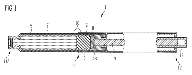
FIG. 1 schematically shows a side view of an embodiment of a drug
delivery device.
FIG. 2 shows a schematic view of the distal end of a first embodiment of a
piston rod.
FIGS. 3A and 3B show schematic views of a second embodiment of a piston rod
before (Fig. 3A) and after (Fig. 3B) plastic deformation.
FIGS. 4A and 4B show schematic views of the distal end of a third embodiment
of a
piston rod before (Fig. 4A) and after (Fig. 4B) plastic deformation; in
Fig. 4B the piston rod abuts a bung.
FIGS. 5A and 5B show schematic views of the distal end of a fourth embodiment
of a
piston rod before (Fig. 5A) and after (Fig. 513) plastic deformation; in
Fig. 5B the piston rod abuts a bung.
CA 02773844 2012-03-09
WO 2011/039226 PCT/EP2010/064419
16
FIG. 6 shows a view of the distal end of a piston rod according to a fifth
embodiment, the piston rod comprising a bearing.
FIG. 7 shows a view of the distal end of a piston rod according to a sixth
embodiment comprising a bearing and an inductively heatable
element.
FIGS. 8A to 8C show schematic views of the distal end of a seventh embodiment
of
a piston rod comprising a bearing before (Fig. 8A and Fig. 8B) and
after (Fig. 8C) plastic deformation. Fig. 8B additionally shows the
area of the piston rod brought into a plastically deformable state of
matter by heating.
Elements of the same kind and identically acting elements may be provided with
the
same reference numerals in the figures.
In FIG. 1, a drug delivery device 1 is shown. The drug delivery device
comprises a body
2 and a cartridge holder 7, the body 2 and the cartridge holder 7 being
elements of the
housing 10. The housing 10 has a distal end 11A and a proximal end 12; the
body 2 has
a distal end 11 and the same proximal end 12 as the housing 10. A cartridge 5
is
located in the cartridge holder 7; the cartridge holder 7 may stabilize the
cartridge 5
mechanically. The cartridge 5 contains a drug, preferably a plurality of doses
of drug.
The drug preferably comprises a liquid medication, for example insulin, e.g.
short-acting
or long-acting insulin, GLP-1, heparin or growth hormones.
The cartridge 5 may comprise an outlet (not explicitly shown) which may be
covered by
a membrane. The drug can be dispensed from the cartridge 5 through the outlet
when
the membrane is pierced. Further, the drug delivery device 1 may comprise
means for
securing a needle assembly (not explicitly shown) to the cartridge holder 7.
The needle
assembly may pierce the membrane when the drug delivery device 1 is operated.
Operating the drug delivery device 1 (i.e. setting and dispensing a dose)
involves
movement of the dosing element 18.
CA 02773844 2012-03-09
WO 2011/039226 PCT/EP2010/064419
17
The drug delivery device 1 comprises a piston rod 3 with a plastically
deformed area 4B
at its distal end. At the distal face of the piston rod, a bearing 8 is
arranged, the bearing
abutting the bung 6 retained in the cartridge 5. Particularly the bearing 8 is
not
contained in all embodiments according to the present invention.
The piston rod 3 provided for the method of assembling the drug delivery
device 1 is
initially usually located almost entirely within the body 2 and usually lies
on the main
axis of the drug delivery device 1. During assembly, the cartridge 5 is placed
into the
cartridge holder 7. The distal end of the piston rod 3 (more generally: the
predetermined
area of weakness 4A) is brought into (or is already in) a plastically
deformable state of
matter. The body 2 retaining the piston rod 3 is connected to the cartridge
holder 7
comprising the cartridge 5. The drive mechanism retained in the body 2 of the
drug
delivery device 1 is loaded in order to simulate forces that would be seen
during dose
dispense in order to correctly take up tolerances of the mechanism during
assembly.
During this stage of final assembly, the piston rod 3 comes into contact with
the bung 6
and the piston rod 3 (particularly the area of weakness 4A) controllably
plastically
deforms and the length of the piston rod 3 is adjusted. In this instance, the
piston rod 3
is assembled such that it is under load as it contacts the bung 6. Finally,
upon cooling
(or after having carried out a chemical reaction), the piston rod 3 becomes
rigid and now
contains the plastically deformed area 4B and remains in contact with the bung
6. Any
gap having been present between bung 6 and piston rod 3 is now removed.
The piston rod 3 may be of unitary or multi-part construction. Thus, the
piston rod 3 may
contain several elements or may be just a one-piece element. In a piston rod 3
containing two or more elements, just one element, two elements or even more
elements may be necessary for the step of plastical deformation (thereby
adjusting the
length of the piston rod). In case of a multi-part construction usually the
plastically
deformed part and a further part or further parts of the piston rod are not
designed to be
permanently fixed to each other after step B has been carried out.
Particularly, a
bearing 8 may be one of the elements of the piston rod 3, the bearing
facilitating
interaction of the piston rod 3 and the bung 6.
CA 02773844 2012-03-09
WO 2011/039226 PCT/EP2010/064419
18
The piston rod 3 is movable with respect to the cartridge 5. Movement of the
piston rod
3 in distal direction with respect to the cartridge causes the drug to be
dispensed from
the cartridge through the outlet.
The housing 10 may be designed to enable a safe and comfortable handling of
the drug
delivery device 1. The housing 10 may be configured to house, fix, protect and
guide
inner components of the drug delivery device, e.g. piston rod 3 and dosing
element 18.
Preferably, the housing 10 limits or prevents exposure of the inner components
to
contaminants such a liquid, dirt or dust. The housing 10 may comprise a
tubular or a
cylindrical shape; alternatively, the housing 10 may comprise a non-tubular
shape.
The drug delivery device 1 may be a pen-type device and may be disposable or
reusable. The device may be configured to dispense fixed doses of the drug or
variable,
preferably user-settable doses of the drug. Particularly for a fixed dose
device, it may be
crucial that there is no gap between the piston rod and the bung.
The drug delivery device 1, particularly the body 2 may comprise a drive
mechanism
(not explicitly shown in the figures). The drive mechanism may be retained
within the
body 2. The specific mechanism for moving the piston rod in distal direction
is omitted in
FIG. 1 for the purpose of clarity as the mechanisms being relevant for the
method for
assembling the drug delivery device according to the present invention and the
mechanisms being relevant for the method for setting and dispensing doses of
the drug
are usually independent from each other. During the set-and-dispense mode, the
direction of movement of the piston rod may be a movement in distal direction
only (in
this embodiment, the bearing 8 is usually not present) or may also comprise
the
movement of the piston rod around its axis (the axis extending from the distal
end to the
proximal end).
When delivering a dose of the drug, due to an operation of the dosing element
18, a
movement of the piston rod 3 in distal direction is caused. The user may
displace the
dose member 18 in the proximal direction with respect to the housing 10 for
setting a
dose of the drug. Afterwards, the user may displace the dosing element 18 in
the distal
direction with respect to the housing 10 for delivering the set dose of the
drug.
CA 02773844 2012-03-09
WO 2011/039226 PCT/EP2010/064419
19
The cartridge holder 7 and the body 2 may be adapted to releasably engage with
each
other or may be irreversibly fixed to each other (e.g. by means of an adhesive
or
mechanical clip). The cartridge holder 7 may be connectable to the body 2 of
the drug
delivery device 1, for example by means of a releasable connection.
FIG. 2 shows the distal end of a first embodiment of a piston rod 3. The
distal end
comprises the distal face 11 P as well as a predetermined area of weakness 4A
having a
hemispherical geometry comprising two bars separated by two openings 15. The
distal
end of the piston rod 3 is designed so that upon applying a force in axial
direction, the
disk-type part of the piston rod comprising the distal face 11 P is pushed
towards the
main part of the piston rod and a plastic deformation of the predetermined
area of
weakness 4A having a hemispherical geometry takes place.
FIGS. 3A and 3B show the distal end of a second embodiment of a piston rod 3
being
similar to the embodiment of FIG. 2. The piston rod 3 comprises a distal face
11 P and a
predetermined area of weakness 4A shown in FIG. 3A. The piston rod 3 (or more
precisely, the predetermined area of weakness 4A) is brought into a state of
matter
which allows plastic deformation (e.g. by heating, shown in FIG. 3A with a
hatching
rising rightwards). Upon applying a force in direction of the axis extending
from the
distal end to the proximal end of the piston rod 3 a deformation of the
predetermined
area of weakness 4A takes place. Upon this movement, again, the disk-shaped
part of
the piston rod comprising the proximal face 11 P is pushed towards the main
part of the
piston rod 3 upon which the predetermined area of weakness 4A is converted
into the
plastically deformed area 4B. This movement may involve a deformation of the
bent
parts of the predetermined area of weakness 4A so that the most distal part of
the
plastically deformed area 4B touches the disk-shaped component of the piston
rod 3.
Thereby, the step involving the plastic deformation of the piston rod 3 may
give rise to
an improved mechanical stability of the distal end of the piston rod 3.
FIGS. 4A and 4B show the distal end of a third embodiment of a piston rod 3.
The
geometry of the piston rod is designed to encourage controlled, axial collapse
of the
distal end of the piston rod under load, particularly when the predetermined
area of
weakness 4A is heated. The geometry of the piston rod 3 according to this
embodiment
comprises a plurality of openings 15 having an extension in the direction of
the axis 16
CA 02773844 2012-03-09
WO 2011/039226 PCT/EP2010/064419
(being defined by the line spanned between the proximal end of the piston rod
3 and the
distal face 11 P, particularly the center of the distal face 11 P of the
piston rod) being
much longer than the extension in the direction perpendicular to the axis 16
(resembling
a lantern-like shape). FIG. 4B shows the situation after applying a force in
the direction
5 of the axis 16 (shown by an arrow) on the piston rod 3 being in a state of
matter that
allows plastic deformation. The extension of the openings 15 in the direction
perpendicular to the axis 16 is shortened much more than the extension in the
direction
of the axis 16. The piston rod 3 abuts on the bung 6 retained in the cartridge
5, more
precisely, the distal face 11 P of the piston rod 3 abuts on the proximal face
12B of the
10 bung 6. The deformation of the predetermined area of weakness 4A gives rise
to a
plastically deformed area 4B having an extension in the direction of the axis
16
shortened with respect to the extension in the direction of the axis 16 of the
predetermined area of weakness 4A.
15 FIGS. 5A and 5B show the distal end of a fourth embodiment of a piston rod
3 being
designed to encourage controlled axial collapse of the piston rod under load.
The piston
rod according to this embodiment comprises a plurality of elements being more
easily
compressible by applying of a force in the direction of the axis 16 than a
piston rod 3
containing no recesses. The predetermined area of weakness 4A in FIG. 5A has a
20 bellowed shape. Upon application of a force in the direction of the axis
(shown by an
arrow in FIG. 5B), the proximal face 12B of the bung 6 abuts on the distal
face 11 P of
the piston rod 3. The piston rod 3 is, for example in a heated and plastically
deformable
state of matter and the area with bellowed shape is pushed so that the
extension of the
plastically deformed area 4B in the direction of the axis 16 is shortened
compared to the
extension of the plastically deformable area 4A of FIG. 5A.
FIG. 6 shows the distal end of a fifth embodiment of a piston rod 3, the
piston rod
comprising at least two elements. The element arranged at the most distal part
of the
piston rod 3 comprising the distal face 11 P of the piston rod is constructed
to be a
bearing 8. The piston rod further comprises a predetermined area of weakness
4A.
FIG. 7 shows the distal end of a sixth embodiment of a piston rod 3, being
similar to the
embodiment shown in FIG. 6. Again, the distal face 11 P of the piston rod 3 is
a part of
the bearing 8. Between the distal end of the main part of the piston rod 3
(comprising
CA 02773844 2012-03-09
WO 2011/039226 PCT/EP2010/064419
21
the predetermined area of weakness 4A), an inductively heatable element 14
with a ball
shape is located. The inductively heatable element 14 may, for example, be
made of a
metal and may comprise an inductively heatable material on its surface.
However, also
an inductively heatable core and a surface made from a heat transporting
material are
possible.
FIGS. 8A to 8C show the distal end of a seventh embodiment of a piston rod 3.
The
state of matter before plastic deformation takes place is depicted in FIG. 8A,
the distal
end of the piston rod 3 comprises a bearing 8, the bearing 8 comprising the
distal face
11 P of the piston rod 3. The most distal part of the main element of the
piston rod 3
comprises the predetermined area of weakness 4A.
In FIG. 8B, the step of selectively heating an area of the piston rod 3 is
shown. The
heated part of the piston rod 3 is designed with a checked pattern. For
example, the
bearing 8 may be made of a metal or even of an inductively heatable material;
therefore,
the predetermined area of weakness 4A may be heated by inductively heating the
bearing 8; otherwise, heating of the predetermined area of weakness 4A, for
example
by means of a concentrated light source, may also involve heating a bearing 8
being
made of a heat transporting material. If, however, the proximal face of the
bung (not
shown) is sensitive against heat, the lower part of the bearing 8 comprising
the distal
face 11 P of the piston rod 3 may be made of a material with a low heat
conduction.
FIG. 8C shows the distal end of the piston rod 3 after plastic deformation.
The distal
face 11 P of the piston rod 3 abuts on the proximal face of the bung (not
shown) and the
main element of the piston rod 3 is pushed towards the bearing 8 having the
effect that
the predetermined area of weakness 4A is plastically deformed and that the
diameter of
the predetermined area of weakness 4A (in the direction perpendicular to the
axis) is
widened; the plastically deformed area 4B results.
The present examples and embodiments are to be considered as illustrative and
not
restrictive, and the invention is not to be limited to the details given
herein, but may be
modified within the scope and equivalence of the appended claims.
CA 02773844 2012-03-09
WO 2011/039226 PCT/EP2010/064419
22
Reference numerals
1 drug delivery device
2 body
3 piston rod
4A predetermined area of weakness
4B plastically deformed area
5 cartridge
6 bung
7 cartridge holder
8 bearing
10 housing
11 distal end of the body
11A distal end of the housing
11 P distal face of the piston rod
12 proximal end of the body and the housing
12B proximal face of the bung
14 inductively heatable element
15 opening
16 axis between the proximal end of the piston rod and thedistal face of the
piston
rod
18 dosing element