Note: Descriptions are shown in the official language in which they were submitted.
CA 02774436 2017-02-01
1
DETECTION OF OBJECTS
Technical Field
The present invention relates to the detection of objects.
Background Art
It is well known to use electromagnetic radiation to detect the presence of
objects
(e.g. handheld detectors used for detecting objects on or under the ground,
and walk-
through arches at airports). However, the conventional detectors used at
airports may be
unable to determine the dimensions of objects to any significant degree, and
thus may be
unable to distinguish between objects of different types, i.e. harmless (belt
buckles,
cameras), and potentially dangerous (guns, knives).
The use of microwaves (electromagnetic waves with wavelengths in the
centimetre to millimetre range) may provide a means for the standoff detection
and
identification of concealed conducting items such as handguns and knives.
Large metal
objects, such as handguns, may give a significantly different and generally
larger
response when irradiated by low power microwaves than the human body, clothing
and/or
benign normally-carried objects. The larger response may be detected using a
combination of antenna and receiver. When an object is illuminated with swept
and/or
stepped frequency microwave radiation, the frequency response of radiation
returned
from the object may provide information regarding dimensions of the object.
It is desirable to provide a system which is capable of detecting objects, for
example knives, in a manner which is not disclosed in the prior art.
Summary of the Invention
According to a first aspect of the invention there is provided a detection
method
comprising:
directing radiation such that the radiation is incident upon a target, the
radiation
containing a component having a first polarisation, and detecting radiation
which is
scattered from the target;
subsequently transmitting radiation such that the subsequently transmitted
radiation is incident upon the target, the subsequently transmitted radiation
containing a
component having a different polarisation which is non-orthogonal to the first
polarisation,
CA 02774436 2017-02-01
la
and detecting the subsequently transmitted radiation which is scattered from
the target,
the radiation which is scattered from the target and the subsequently
transmitted radiation
which is scattered from the target comprising detected scattered radiation;
and
analysing a polarisation state of the detected scattered radiation to
determine
whether the target includes an object.
Using radiation containing a component having a first polarisation and a
second
orthogonal polarisation is advantageous because it avoids the possibility that
the
CA 02774436 2012-03-16
WO 2011/033264 PCT/GB2010/001744
2
radiation is orthogonal or parallel to an anisotropic object such as a knife.
If the
radiation were to be orthogonal or parallel to an anisotropic object (as could
happen in
a prior art detection method) then this might cause a zero or very small
signal to be
detected such that the presence of the knife or other anisotropic object is
not detected.
The term 'polarisation state' may be interpreted as encompassing a
comparison of the relative size of polarisation components of the detected
scattered
radiation in a given reference frame (e.g. a pair of orthogonal axes).
The detection method may use the amplitude of the detected scattered
radiation in addition to the polarisation state. The amplitude may for example
provide
an indication of the size of a scattering surface of an object. In this
context the term
amplitude may include measurements such as the intensity of the detected
scattered
radiation.
The analysis may comprise comparing the polarisation state of the detected
scattered radiation with polarisation sates of scattered radiation which would
be
expected if an object was present.
The radiation may be swept frequency radiation. Using swept frequency
radiation may provide information about the depth of the object (i.e. the size
of object in
a direction substantially parallel to the direction of propagation of the
radiation). This
may assist in determining whether the object is a threat object or a non-
threat object,
and may assist the identification of the object.
The analysis may comprise comparing a pattern in the frequency response of
the detected scattered radiation with previously recorded patterns, or
performing an
equivalent comparison in the time domain.
The analysis may determine whether the object is a threat object or a non-
threat object.
The analysis may provide an identification of the object. This may be
performed using a classification method based upon comparing a pattern in the
frequency response of the detected scattered radiation with previously
recorded
patterns and looking for a match or a correlation (or other correspondence).
The detected scattered radiation may be cross-polarised scattered radiation.
The radiation may be provided with a rotating linear polarisation.
The radiation may be detected using a receiver which provides rotating
detection of linear polarisation.
CA 02774436 2017-02-01
3
The radiation may be detected using a first receiver configured to receive
radiation
having a first linear polarisation and a second receiver configured to receive
radiation
having a second linear polarisation.
The radiation may be generated using a first transmitter configured to
transmit
radiation having a first linear polarisation and is subsequently generated
using a second
transmitter configured to transmit radiation having a second linear
polarisation.
The radiation may be detected using a first receiver configured to receive
radiation
having a third linear polarisation and a second receiver configured to receive
radiation
having a fourth linear polarisation.
The third linear polarisation may be substantially orthogonal to the first
linear
polarisation and the fourth linear polarisation is substantially orthogonal to
the second
linear polarisation.
The second linear polarisation may subtend an angle of around 45 relative to
the
first linear polarisation.
The radiation may be generated using a transmitter with transmits circularly
or
elliptically polarised radiation.
The detected scattered radiation may be received by a receiver which is
configured
to receive radiation having the same handedness of polarisation as the
transmitted
radiation.
The method may further comprise, when an object is present, analysing the
polarisation of the detected scattered radiation as a function of frequency to
determine
whether the object is a threat object or a non-threat object.
The method may further comprise analysing the polarisation of the detected
scattered radiation as a function of frequency to identify the object.
The swept frequency radiation may comprise radiation which is stepped through
a
plurality of discrete frequencies.
Optionally, the analysis of the detected scattered radiation does not include
phase
information.
Optionally, the analysis of the detected scatter radiation includes phase
information.
The analysis may be performed using an artificial neural network or equivalent
software which has been previously trained to identify objects.
According to a second aspect of the invention there is provided a detection
system
comprising a transmitter configured to direct radiation containing a component
having a
first polarisation such that the radiation is incident upon a target, the
transmitter being
configured to subsequently direct radiation such that the subsequently
directed radiation
CA 02774436 2017-02-01
4
is incident upon the target, the subsequently directed radiation containing a
component
having a different polarisation which is non-orthogonal to the first
polarisation, wherein the
detection system further comprises a receiver and detector configured to
receive and
detect radiation which is scattered from the target, and a processor which is
configured to
analyse a polarisation state of the detected scattered radiation to determine
whether the
target includes an object.
The detection system may be sufficiently portable that it may be used in a
hand
held manner.
The detection system may be further configured to implement one or more
elements of the detection method referred to above.
Some embodiments of the present invention may include a recorded or recordable
medium having recorded or stored thereon digital data defining or
transformable into
instructions for execution by processing circuitry, the instructions
corresponding the
methods described herein.
Some embodiments of the present invention may include a server comprising
processing circuitry, memory and a communications device, the server being
programmed
for communicating on demand or otherwise digital data defining or
transformable into
instructions for execution by processing circuitry, the instructions
corresponding to the
methods described herein.
The invention may provide detection of threat objects at stand-off distances.
Brief Description of the Figures
Embodiments of the invention will now be described in detail, by way of
example,
with reference to the accompanying drawings, in which:
Figure 1 is a schematic diagram which shows an object detection system
according to an embodiment of the invention,
Figure 2 is a graph which shows the intensity of radiation scattered from a
kitchen
knife as a function of angle using the object detection system of Figure 1;
Figure 3 illustrates two possible orientations of a knife to be detected using
the
object detection system;
Figure 4 is a graph which shows the magnitude of cross-polarisation S. and S.
scattering parameters as simulated for a kitchen knife over the frequency
range of 0.1 -
20 GHz;
Figure 5 is a graph which shows the magnitude of co-polarisation S. and Szz
scattering parameters as simulated for the kitchen knife over the frequency
range of 0.1 -
20 GHz;
CA 02774436 2012-03-16
WO 2011/033264 PCT/GB2010/001744
Figure 6 is a graph which shows the magnitude of cross-polarisation Sn and
S. scattering parameters as simulated for a revolver type handgun over the
frequency
range of 0.1 - 20 GHz;
Figure 7 is a graph which shows the magnitude of co-polarisation S., and Sn
5 scattering parameters as simulated for the revolver type handgun over the
frequency
range of 0.1 - 20 GHz;
Figure 8 is a schematic diagram which shows an object detection system
according to an alternative embodiment of the invention;
Figure 9 is a schematic diagram which shows an object detection system
according to a further alternative embodiment of the invention; and
Figure 10 is a schematic diagram which shows an object detection system
according to a further alternative embodiment of the invention.
Detailed Description of Embodiments
Embodiments of the present invention now will be described more fully
hereinafter with reference to the accompanying drawings, in which embodiments
of the
invention are shown. This invention may, however, be embodied in many
different
forms and should not be construed as limited to the embodiments set forth
herein.
Rather, these embodiments are provided so that this disclosure will be
thorough and
complete, and will fully convey the scope of the invention to those skilled in
the art.
It will be understood that, although the terms first, second, etc. may be used
herein to describe various elements, these elements should not be limited by
these
terms. These terms are only used to distinguish one element from another. For
example, a first element could be termed a second element, and, similarly, a
second
element could be termed a first element, without departing from the scope of
the
present invention. As used herein, the term "and/or" includes any and all
combinations
of one or more of the associated listed items.
It will be understood that when an element such as a layer, region or
substrate
is referred to as being "on" or extending "onto" another element, it can be
directly on or
extend directly onto the other element or intervening elements may also be
present. In
contrast, when an element is referred to as being "directly on" or extending
"directly
onto" another element, there are no intervening elements present. It will also
be
understood that when an element is referred to as being "connected" or
"coupled" to
another element, it can be directly connected or coupled to the other element
or
CA 02774436 2012-03-16
WO 2011/033264 PCT/GB2010/001744
6
intervening elements may be present. In contrast, when an element is referred
to as
being "directly connected" or "directly coupled" to another element, there are
no
intervening elements present.
Relative terms such as "below" or "above" or "upper" or "lower" or
"horizontal"
or "vertical" may be used herein to describe a relationship of one element,
layer or
region to another element, layer or region as illustrated in the Figures. It
will be
understood that these terms are intended to encompass different orientations
of the
device in addition to the orientation depicted in the Figures.
The terminology used herein is for the purpose of describing particular
embodiments only and is not intended to be limiting of the invention. As used
herein,
the singular forms "a", "an" and "the" are intended to include the plural
forms as well,
unless the context clearly indicates otherwise. It will be further understood
that the
terms "comprises", "comprising," "includes" and/or "including" when used
herein,
specify the presence of stated features, integers, steps, operations,
elements, and/or
components, but do not preclude the presence or addition of one or more other
features, integers, steps, operations, elements, components, and/or groups
thereof.
Unless otherwise defined, all terms (including technical and scientific terms)
used herein have the same meaning as commonly understood by one of ordinary
skill
in the art to which this invention belongs. It will be further understood that
terms used
herein should be interpreted as having a meaning that is consistent with their
meaning
in the context of this specification and the relevant art and will not be
interpreted in an
idealized or overly formal sense unless expressly so defined herein.
The present invention includes methods which may be implemented in an
automated manner, and may comprise computer program instructions. These
computer program instructions may be stored or implemented in a
microcontroller,
microprocessor, digital signal processor (DSP), field programmable gate array
(FPGA),
a state machine, programmable logic controller (PLC) or other processing
circuit,
general purpose computer, special purpose computer, or other programmable data
processing apparatus such as to produce a machine, such that the instructions,
which
execute via the processor of the computer or other programmable data
processing
apparatus, create means for implementing the functions/acts of the methods.
These computer program instructions may also be stored in a computer
readable memory that can direct a computer or other programmable data
processing
apparatus to function in a particular manner, such that the instructions
stored in the
computer readable memory produce an article of manufacture including
instruction
CA 02774436 2012-03-16
WO 2011/033264 PCT/GB2010/001744
7
means which implement the function/act specified in the flowchart and/or block
diagram
block or blocks.
The computer program instructions may also be loaded onto a computer or
other programmable data processing apparatus to cause a series of operational
steps
to be performed on the computer or other programmable apparatus to produce a
computer implemented process such that the instructions which execute on the
computer or other programmable apparatus provide steps for implementing the
methods. It is to be understood that individual functions/acts of a method
may, where
the context allows, be performed in an order which differs from the described
order.
Embodiments of the invention may be used for remotely detecting the presence
and/or size of metal and/or dielectric objects concealed underneath clothing.
Embodiments herein may be used for remotely detecting metal and/or dielectric
objects. A dielectric in this context is a non-conducting (i.e. insulating)
substance such
as ceramic that has a low enough permittivity to allow microwaves to pass
through. A
ceramic knife or gun are examples of dielectric objects. Embodiments of the
invention
may detect objects which are anisotropic and/or which include anisotropic
edges.
Embodiments of the invention may be particularly suited to detecting metal
objects
which are anisotropic and/or which include anisotropic edges.
Embodiments of the invention may direct swept frequency radiation (which may
comprise stepped frequency radiation) at a target and detect radiation which
is
scattered from the target. Embodiments of the invention may detect the
amplitude and
phase of the scattered radiation or may detect the amplitude of the scattered
radiation
without detecting the phase. Detection of the amplitude and phase may be
referred to
as quadrature detection, and detection of the amplitude only may be referred
to as
direct detection. In this context the term 'amplitude' may be considered to
encompass
the square of the amplitude (irradiance) or other related measurements. From a
mathematical point of view, the use of swept frequency radiation may be
considered to
be similar to using a fast microwave pulse and measuring the response as
function of
time (as used in conventional radar).
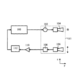
Figure 1 is a schematic diagram of an object detection system according to an
embodiment of the invention which uses direct detection. The object detection
system
includes a microwave source 100 which is connected via a frequency multiplier
102 to
a gain horn that acts as a transmitter 104. The transmitter 104 is configured
to transmit
microwave radiation over a range of frequencies. Focussing optics (not shown)
may
be used in combination with the gain horn to focus the radiation such that the
radiation
CA 02774436 2012-03-16
WO 2011/033264 PCT/GB2010/001744
8
is incident upon a person being monitored with a desired cross-sectional beam
area,
which may be commensurate with the size of the object being detected. A second
gain
horn acts as a receiver 106 which is configured to receive radiation scattered
from the
person being monitored. The transmitter 104 and the receiver 106 (and
associated
focussing optics) may be located adjacent to one another or may be spaced
apart from
one another. The receiver passes received scattered radiation to a detector
108 which
detects the radiation and provides an electrical output signal. An amplifier
110, which
is connected to the detector 108, is configured to amplify output from the
detector and
pass the amplified output to a computer 112 (or other data capturing and
processing
apparatus). The amplitude of detected scattered radiation may be stored by the
computer 112 as a function of the radiation frequency. Properties of the
detected
scattered radiation are analysed by the computer 112, which thereby identifies
the
presence of an object and which may identify the nature of the object. The
properties
which are analysed may include the form of patterns in the detected scattered
radiation
as a function of frequency. The manner in which the detected scattered
radiation is
analysed is described further below.
The transmitter 104 may be configured to transmit radiation with a first
polarisation, and the receiver 106 may be configured to receive radiation with
a second
polarisation which is orthogonal to the first polarisation. This may be
referred to as
cross-polarisation detection. Referring to the Cartesian coordinates indicated
in Figure
1, the transmitter 104 may for example be configured to transmit radiation
which is
polarised in the x-direction and the receiver 106 may for example be
configured to
receive radiation which is polarised in the z-direction. The Cartesian
coordinates in
Figure 1 (and in other figures) are provided to facilitate explanation, and
are not
intended to imply that the detection system has any particular orientation.
The transmitter 104 and the receiver 106 may both be rotatably mounted, such
that they may rotate whilst transmitting and receiving radiation. The rotation
may be
about an axis which is perpendicular to the polarisation directions of the
transmitter 104
and receiver 106 (e.g. about an axis which is parallel to the y-axis). The
transmitter
104, frequency multiplier 102, receiver 106 and detector 108 may all be held
on a
rotatable frame 111 which rotates about an axis parallel to the y-axis.
Rotating the
receiver 106 and detector 108 using the same frame provides the advantage that
their
rotations are synchronised (separate synchronisation control is not needed). A
microwave sliding joint may be used to channel microwaves from the non-
rotating
microwave source 100 to the rotating frequency multiplier 102. In other
embodiments
CA 02774436 2012-03-16
WO 2011/033264 PCT/GB2010/001744
9
more or fewer components may be held in the rotatable frame 111. In
alternative
embodiments the transmitter 104 and receiver 106 may be mounted to rotate
separately (i.e. not mounted on a single rotatable frame). Where this is the
case,
rotation of the transmitter 104 and receiver 106 may be synchronised by a
synchronisation control such that the polarisation directions of the
transmitter and the
receiver remain orthogonal to one another.
In an alternative embodiment, instead of rotating the transmitter 104 and
receiver 106, the transmitter and/or receiver may be non-rotating but may
include
electronics which provide equivalent rotation of their polarisation
orientation. An
advantage of this embodiment is that it has no moving parts. The electronics
may for
example utilise Faraday rotation.
The rotation of the transmitter 104 will cause the polarisation of the
radiation
transmitted by the transmitter to rotate about the y-axis. Similarly, the
rotation of the
receiver 106 will cause the receiver to detect radiation having a polarisation
which
rotates about the y-axis. Since the rotation of the receiver 106 is
synchronised with the
rotation of the transmitter 104, the polarisation direction of the receiver is
always
orthogonal to the polarisation direction of the transmitter. As a result, the
polarisation
of detected radiation is always perpendicular to the polarisation of
transmitted radiation
(i.e. cross-polarisation detection occurs).
The electromagnetic radiation transmitted by the transmitter 104 may have a
maximum wavelength which is comparable to or shorter than a long side of an
object
which is to be detected. The object may for example be concealed on the body
of a
person. Radiation may be directed onto the person (not shown in Figure 1)
using the
transmitter 104 such that at least part of the object is illuminated by the
radiation. The
intensity of the transmitted radiation is kept within safe operating limits
(i.e. such that
the health of the person is not affected). The intensity of the transmitted
radiation may
be selected (at least in part) based upon the sensitivity of the detector 108.
The transmission and detection of radiation may be undertaken remotely from
the person monitored (and thus remotely from the object). For example, the
transmitter
104 and receiver 106 may be located 1 metre or more from the person being
monitored. There is no lower limit on the distance between the transmitter 104
and
receiver 106 and the person being monitored. An upper limit of the distance
may arise
from the effectiveness of focussing optics used to focus the radiation, in
combination
with the desired cross-sectional area of the radiation at the person being
monitored. In
some embodiments, possible operating distances for detection system may range
from
CA 02774436 2012-03-16
WO 2011/033264 PCT/GB2010/001744
a few tens of centimetres to many tens of metres, and may range from
approximately 1
metre to approximately 10 metres or more. The possible operating distances may
depend on the frequency of the radiation. This is because some microwave
frequencies are attenuated by the atmosphere. Atmospheric windows such as that
5 found around 94 GHz may be chosen to minimise these effects.
The frequency of the radiation may be swept through a frequency range whilst
the radiation is incident upon the person being monitored. The range of the
frequency
sweep determines the depth resolution of the system (measured in the direction
of
propagation of the radiation). It may therefore be advantageous to maximise
the swept
10 range of frequencies to give greater discrimination between objects. The
swept range
of frequencies may for example correspond with the W band (75-110 GHz;
providing a
sweep range of 35 GHz). The microwave source 100 may generate microwave
radiation with frequencies which are a fraction of the desired frequency
range, and the
frequency multiplier 102 may multiply the frequency of the radiation such that
the
desired frequency range is provided. Other wave bands such as the K and Q
bands
(14-40 GHz; providing a sweep range of 26 GHz) may be used in addition to or
instead
of the W band. In some instances the microwave source 100 may be capable of
generating microwaves having a desired range of frequencies without a
frequency
multiplier being needed. Where this is the case the frequency multiplier may
be
omitted from the detection system. The frequency of the radiation may for
example
extend as high as 300 GHz (radiation above this frequency is not effective at
penetrating clothes). The frequency of the radiation may for example extend as
low as
40 GHz, may extend as low as 1 GHz, and may extend as low as 0.1 GHz. A swept
frequency band of around 10-50 GHz in width within a frequency range of around
40-
300 GHz may be used.
Swept frequency radiation may be provided as a continuous change of the
frequency of radiation transmitted by the transmitter 104. Alternatively, the
swept
frequency radiation may comprise a series of steps of the frequency of
radiation
transmitted by the transmitter 104. At the end of each frequency sweep there
may be
a break in the radiation before the next sweep is begun. All of these
possibilities may
be considered to be examples of continuous wave radiation.
The frequency sweep may begin at a low frequency and extend to a high
frequency, or may begin at a high frequency and extend to a low frequency.
Alternatively, the frequency sweep may pass through different frequencies in a
pseudo-
random order, a random order, or any other suitable order.
CA 02774436 2012-03-16
WO 2011/033264 PCT/GB2010/001744
11
As is explained further above, the transmitter 104 and receiver 106 are
configured to rotate such that the polarisation of the radiation transmitted
by the
transmitter 104 rotates about a line parallel to the y-axis, and the
polarisation of the
radiation received by the receiver 106 also rotates about a line parallel to
the y-axis.
The rotation of the transmitter 104 and receiver 106 is synchronised such that
receiver
polarisation is always orthogonal to the transmitter polarisation (thereby
providing
cross-polarisation detection).
The transmitter 104 and the receiver 106 are rotated whilst the frequency of
the
radiation transmitted by the transmitter is swept through a frequency range. A
plurality
of frequency sweeps and a plurality of full rotations of the transmitter 104
and receiver
106 (i.e. rotation through 360 ) may be performed during monitoring of a
person.
In an embodiment, the duration of a frequency sweep may be shorter than the
duration of a full rotation of the transmitter 104 and receiver 106. Where
this is the
case a plurality of frequency sweeps may take place during a full rotation of
the
transmitter 104 and receiver 106. There is no requirement for the frequency
sweep
and the rotation to be synchronised, and the frequency may therefore have a
different
value at the start and end of a full rotation.
In an alternative embodiment, the duration of a frequency sweep may be longer
than the duration of a full rotation of the transmitter 104 and receiver 106.
Again, there
is no requirement for the frequency sweep and the rotation to be synchronised.
In a further alternative embodiment, the transmitter 104 and receiver 106 may
be rotated in a series of steps (e.g. controlled by stepper motors) through a
series of
orientations. Where this is done, a frequency sweep may be performed when the
transmitter 104 and receiver 106 have a first orientation, then repeated when
the
transmitter and receiver have a second orientation, etc.
The transmitter 104 and receiver 106 may be rotated through less than 360
(for example instead being rotated through 90 ) without significantly reducing
the
accuracy with which objects are identified. This is explained further below.
A sensor, for example an ultrasonic sensor, or a stereoscopic camera may be
used to measure the distance between the transmitter 104 (and receiver 106)
and a
person being monitored. This distance information may be useful because the
cross-
sectional shape of the radiation beam may change as the radiation beam
propagates,
and it is desirable to know the cross-sectional shape of the radiation beam
when
analysing detected scattered radiation (the cross-sectional shape may
influence the
manner in which scattering of the radiation occurs).
CA 02774436 2012-03-16
WO 2011/033264 PCT/GB2010/001744
12
Figure 2 shows data collected using the detection system shown in Figure 1.
The amplitude of detected radiation scattered from a standard kitchen knife
was
recorded as a function of the orientation of the transmitter 104. The
transmitter 104
and the receiver 106 were both rotated through 3600
.
The amplitude response varies as a function of angle 0 according to
sin 0 cos = ¨1sin 20 (i.e. it is sinusoidally modulated with the argument
being twice
2
the angle of rotation). The measured quantity shown in Figure 2 is
proportional to the
power of the detected scattered radiation, which is the square of the
amplitude
response. The shape of the response is indicative of the knife. This is
because the
knife is anisotropic, being elongated in one direction, and therefore gives
rise to
significant scattered radiation with a polarisation which is orthogonal to the
polarisation
of the incident radiation only when the electric field direction does not lie
wholly along
the length of the knife. The detected scattered radiation is strongest when
the
polarisation of the incident radiation is oriented at - 45 (with respect to
the long axis
(blade) of the knife). This is because the incident radiation includes a
substantial
polarisation component which lies in the plane of the edges of the knife blade
and the
radiation which is scattered from the knife includes a substantial
polarisation
component which lies in the plane of the receiver polarisation (the edges of
the knife
cause polarisation modification when scattering radiation). When the
polarisation of
the incident radiation is oriented at 0 relative to the knife blade, the
detected scattered
radiation is at a minimum. This is because although the polarisation of the
incident
radiation lies in the plane of the edges of the knife blade, and therefore
gives rise to
significant scattering, the radiation which is scattered from the knife blade
does not
include a substantial polarisation component which lies in the plane of the
receiver
polarisation. Similarly, when the polarisation of the incident radiation is
oriented at 900
relative to the knife blade, the detected scattered radiation is also at a
minimum. This
is because the polarisation of the incident radiation is perpendicular to the
edges of the
knife blade, and the knife blade therefore does not give rise to significant
scattering of
the incident radiation.
Embodiments of the invention use radiation containing a component having a
first polarisation and a second orthogonal polarisation. This is advantageous
because
it avoids the possibility that the radiation is orthogonal or parallel to a
knife (or other
anisotropic object).
CA 02774436 2012-03-16
WO 2011/033264 PCT/GB2010/001744
13
In addition to including a maximum of detected scattered radiation when the
transmitter is oriented to transmit radiation with a polarisation at 45
relative to the knife
blade, Figure 2 also includes maximums when the transmitter is oriented at 135
, 225
and 315 . This is because the reflection of the incident radiation behaves in
the same
manner when the transmitter has these orientations (the interaction between
the
radiation and the long edges of the knife is the same). Similarly, minimums of
detected
scattered radiation are seen when the transmitter is oriented at 1800 and 270
. The
maximums shown in Figure 2 have different heights. However, these different
heights
arise from a misalignment of the radiation relative to the knife during
measurement
rather than from a property of the detection system itself.
The modulation of the detected scattered radiation shown in Figure 2 indicates
that the knife is either horizontal or vertical (the initial polarisation of
the incident
radiation was horizontal). If the knife had had a different orientation then
the detected
scattered radiation would be shifted relative to the horizontal axis, but the
characteristic
modulated shape of the detected scattered radiation would remain.
The shape of the detected scattered radiation shown in Figure 2, which arises
from the polarisation state of the scattered radiation, is indicative of a
knife for the
reasons explained above. This shape of scattered radiation may be indicative
of other
anisotropic objects and is not limited to knives. This is because the long
edges
(particularly sharp edges) give rise to radiation scattering with an
orthogonal
polarisation, the strength of this scattering varying as a function of the
polarisation of
the incident radiation (and the polarisation of the receiver).
An object which is less anisotropic than a knife, for example a handgun, may
give rise to detected scattered radiation having a polarisation state which
does not give
rise to the shape shown in Figure 2 but which nevertheless gives rise to a
shape which
allows the object to be identified. Conducting materials with a smooth
surface,
including the human body, are mainly polarisation conserving. These will thus
not give
rise to strong cross-polarised detected scattered radiation, and thus will
contribute a
limited amount of noise to the detected scattered radiation. This may allow
objects to
be discriminated from the human body.
In general, the manner in which polarised radiation is scattered from an
object,
and the resulting polarisation state of the scattered radiation, will depend
upon the
shape of that object. This may be characterised using parameters which are
referred
to here as scattering parameters. The following treatment confirms from a
theoretical
CA 02774436 2012-03-16
WO 2011/033264 PCT/GB2010/001744
14
point of view the ability of the detection system to distinguish between
knives and less
anisotropic objects such as handguns.
Scattering parameters are aspect dependent, that is they depend on the
orientation of an object relative to the polarisation of the incident
radiation. However, a
measurement of the scattering parameters in any one aspect allows the
derivation of
the scattering parameters in any other aspect, and the development of a
scattering
surface which is aspect independent in either the frequency domain or the time
domain
(via inverse Fourier transform). The
scattering parameters therefore give a
mathematical description of the detection system's ability to distinguish an
anisotropic
scatterer such as a knife from another more isotropic object such as a mobile
phone. A
measurement of the scattering parameters for a given polarisation of incident
radiation
may be used to determine the scattering parameters for all other polarisations
of
incident radiation. The scattering parameters for all polarisations may be
determined
by the detection system as part of an analysis which identifies an object.
However, this
is not essential, and the analysis may instead use the scattering parameters
of the
detected radiation directly.
Figure 3 shows a knife with two different orientations. In Figure 3a the knife
has
an arbitrary orientation relative to indicated Cartesian coordinates. In
Figure 3b the
knife has been rotated from the arbitrary orientation through an angle O. A
second set
of coordinates (primed), which are co-rotated through the angle O are
indicated in
Figure 3b along with the original set of coordinates (unprimed). The primed
coordinates allow a scattering parameter matrix (S matrix) for the rotated
knife to be
equated to the scattering parameter matrix for the unrotated knife.
The scattering from the an object (e.g. the knife) can be expressed as a
matrix
equation as follows:
E1 IS S1 [E1
E 1=[S, Szz El+z 1
(1)
which is succinctly written as:
E_ = SE, (2)
where E+, and E+, are the incident electric field components (i.e.
polarisation) of the
radiation in the x and z directions respectively and E_x and E_z are the
scattered
electric fields.
CA 02774436 2012-03-16
WO 2011/033264 PCT/GB2010/001744
If the object is now rotated by angle 0 we may, without loss of generality,
define a new coordinate system (primed) such that the scattering parameter
matrix is
identical to that in the unprimed coordinate system as given in equation (2)
(this is what
was done in Figure 3b).
5 Hence in the primed coordinate system scattering from the object may be
written as:
Et = SE (3)
The relationship between the E-field vectors (i.e. polarisations) in the
primed
and unprimed frames (coordinate systems) is easily expressed as:
10 E=RE (4)
where R is the rotation matrix given by:
cos 60 - sine
R=
sin 0 cos 0 (5)
Thus by using equations (3) and (4) the scattering equation for the rotated
object in the unprimed frame may be determined:
15 E_ = .1?-1SRE, (6)
cos 0 sin 0-
where, =
- sin 0 cos
Hence it may be concluded that the S matrix of the object, .5(0), rotated by
angle 0 from its arbitrary zero position, S, is given by the equation:
S(0) = R-I SR (7)
The surface generated by the S matrix S(0) of an object over orientation
angles
of 00 <O< 900 may uniquely identify the scattering object. A simple
explanation of this
is described below, followed by consideration of Figures 4 to 7, which show
surfaces
formed from scattering parameters generated using numerical modelling for a
kitchen
knife and for a revolver type handgun.
The knife may be oriented such that its blade lies along the z-axis (i.e. as
shown
in Figure 3a). Two fixed (non-rotating) receivers may be provided, one aligned
to only
record the z-component of the E field (i.e. radiation having a z-direction
polarisation
component) the other to only record the x-component of the E-field (i.e.
radiation
having an x-direction polarisation component). The knife may be illuminated
first with
CA 02774436 2012-03-16
WO 2011/033264 PCT/GB2010/001744
16
z-direction polarised radiation, then with x-direction polarised radiation. No
scattered
radiation will be received by the receiver which is aligned to record the x-
component of
the E-field, but scattered radiation will be received by the receiver which is
aligned to
record the z-component of the E-field. Thus the scattering parameter matrix in
this
case looks like:
[0 101
(8)
0
This is an approximation which is true for a very long thin target where the
width is
much less than the length. When this approximation applies, according to
Equation 7,
the scattering parameter for the knife rotated through angle O with respect to
the z-axis
is:
s(e).: sin 2 0 sin 0 cos 0
(9)
sin 0 cos 0 cos2 0
It may be seen from consideration of Equation 9 that the maximum cross-
polarised
received scattered radiation is always at 45 degrees, and that the cross-
polarised
received scattered radiation varies as the function sin O cos O.
1 5 Since the s(o) of Equation 9 is symmetric, only one of the cross-
polarised
radiation terms is needed in order to determine the presence of an anisotropic
object
such as the knife. Therefore, it may be possible to determine the presence of
an
anisotropic object such as the knife by illuminating the knife with radiation
having a
given polarisation and measuring the scattered radiation in a perpendicular
polarisation. However, in order to avoid the situation in which the incident
radiation is
not scattered from the knife, radiation having polarisation components in more
than one
orthogonal direction may be required. Similarly, in order to avoid the
situation in which
no radiation scattered from the knife is detected, receivers having
polarisation
components in more than one direction may be required (or a single rotating
receiver
as described further above).
Embodiments of the invention may illuminate an object with radiation having a
given polarisation and measure scattered radiation with a perpendicular
polarisation to
deduce the presence of an anisotropic object such as a knife. Rotation of both
a
transmitter and perpendicular receiver (e.g. as shown in Figure 1), together
allows the
angular dependence of the scattering of radiation by the object to be
determined. If the
angular dependence is of the form sin 0 cos 0 then it may be identified as a
knife (or
CA 02774436 2012-03-16
WO 2011/033264 PCT/GB2010/001744
17
some other strongly anisotropic object). If the angular dependence is not of
the form
sin 0 cos 0 then the object may be something other than a knife.
Figure 4 illustrates the magnitude of the scattering parameters of the kitchen
knife as seen for crossed-polarisation detection (i.e. illumination of the
kitchen knife
using radiation having an E-field vector (polarisation) in a first direction
and detection of
the E-field vector in an orthogonal direction). The scattering parameters
determine the
polarisation state of crossed-polarisation detected scattered radiation that
will be seen
when radiation is directed at the kitchen knife. In Figure 4a the kitchen
knife is
illuminated using radiation polarised in the z-direction and radiation
polarised in the x-
direction is detected. The kitchen knife is rotated through 900 (equivalently,
the kitchen
knife may be stationary and the E-field vectors may be rotated). The frequency
of the
radiation is scanned from 0.1 to 20 GHz. This is lower than the range of
frequencies
that is likely to be used by embodiments of the invention, but is the
frequency range
which was available in the numerical model. The numerical model provides a
surface
Szt of scattering parameters which has a form that identifies a strongly
anisotropic
object, in this case the kitchen knife. Figure 4a demonstrates that the
scattering
parameters vary strongly as a function of frequency. At frequencies above
around 8
GHz a maximum of the scattering parameters may be seen at 45 degrees, the
magnitude of the maximum increasing as the frequency increases. This maximum
indicates that the strongest cross-polarised scattering is seen when the
kitchen knife is
oriented at 45 , for the reasons explained further above in relation to Figure
2. In
Figure 4b the kitchen knife is illuminated using radiation polarised in the x-
direction and
radiation polarised in the z-direction is detected. This provides a surface
Szx of
scattering parameters. As can be seen from comparison of Figures 4a and 4b,
the
surface of scattering parameters is the same as the surface of the scattering
parameters in Figure 4a. The maximum at 45 again indicates that the strongest
cross-
polarised scattering is seen when the kitchen knife is oriented at 45 . A
strong
maximum of the kind shown in Figures 4a and 4b is indicative of a strongly
anisotropic
object such as a kitchen knife.
The simple shape of the surface of the scattering parameters shown in Figure 4
=
is indicative of an object which is strongly anisotropic and which is
symmetric (or
substantially symmetric) about its axis. Detection of scattering radiation
with an
intensity which varies in the manner shown in Figure 4 (or a similar manner)
may
indicate the presence of a knife. Thus, detection of scattered radiation which
varies as
CA 02774436 2012-03-16
WO 2011/033264 PCT/GB2010/001744
18
sin 0 cos 0 (or a similar form) as a function of angle may indicate the
presence of a
knife. Other objects which are less simple in shape than a knife and which are
less
anisotropic may give rise to a more complex surface of cross-polarised
scattering
parameters, for example as discussed further below in relation to Figure 6.
Figure 5 illustrates the magnitude of the scattering parameters of the kitchen
Knife as seen for co-polarisation detection (i.e. illumination of the object
using radiation
having an E-field vector (polarisation) in a first direction and detection of
the E-field
vector in the same direction). In Figure 5a the kitchen knife is illuminated
using
radiation polarised in the x-direction and radiation polarised in the x-
direction is
detected. The frequency of the radiation is scanned from 0.1 to 20 GHz, and
the
kitchen knife is rotated through 900. It can be seen that at frequencies above
around 8
GHz a maximum is seen when the knife is oriented in the x-direction. In Figure
5b the
kitchen knife is illuminated using radiation polarised in the z-direction and
radiation
polarised in the z-direction is detected. It can be seen that at frequencies
above
around 8 GHz a maximum is seen when the knife is oriented in the z-direction.
Strong
maximums of the kind shown in Figures 5a and 5b are indicative of a strongly
anisotropic object such as a kitchen knife (strong co-polarised scattering is
seen when
the polarisation has a large component that is parallel to the long direction
of the
anisotropic object).
Figure 6 illustrates the magnitude of the scattering parameters of a revolver
type handgun as seen for crossed-polarisation detection. In Figure 6a the
handgun is
illuminated using radiation polarised in the z-direction and radiation
polarised in the x-
direction is detected. The handgun is rotated through 90 and the frequency of
the
radiation is scanned from 0,1 to 20 GHz. The scattering parameters vary
strongly as a
function of frequency, and provide a surface of Szx scattering parameters
which has a
form that may identify the revolver type handgun. Peaks are seen in the
surface of
scattering parameters at different frequencies and for different orientations
of the
handgun. These peaks correspond to scattering of the radiation by parts or
features of
the handgun, the strength of the scattering depending on the size and
orientations of
those parts or features of the handgun. Since the handgun has many parts or
features,
at least one of these parts or features is likely to provide significant cross-
polarised
scattering for a given orientation of the handgun. In Figure 6b the revolver
type
handgun is illuminated using radiation polarised in the x-direction and
radiation
polarised in the z-direction is detected. This provides a surface of Su
scattering
parameters. As can be seen from comparison of Figures 6a and 6b, the surface
of
CA 02774436 2012-03-16
WO 2011/033264 PCT/GB2010/001744
19
scattering parameters in Figure 6b is the same as the surface of the
scattering
parameters in Figure 6a. Thus, the surfaces of scattering parameters may be
used to
identify the revolver type handgun.
Figure 7 illustrates the magnitude of the scattering parameters of the
revolver
type handgun as seen for co-polarisation detection (i.e. illumination of the
object using
radiation having an E-field vector (polarisation) in a first direction and
detection of the
E-field vector in the same direction). The handgun is rotated through 900 and
the
frequency of the radiation is scanned from 0.1 to 20 GHz. The surfaces of the
scattering parameters in Figures 7a and 7b do not include distinctive peaks of
the type
seen in Figures 6a and 6b. This demonstrates that co-polarisation detection
may be
less suited than cross-polarisation detection to identifying objects,
particularly
anisotropic objects. In addition, cross-polarisation detection may provide
better
discrimination of an object from the body of a person carrying the object
(compared
with co-polarisation detection), because the radiation scattered by the body
will be
dominated by co-polarised radiation. Co-polarisation detection may be used in
combination with cross-polarisation detection. This may aid discrimination of
an object
from the body of a person carrying the object than would be achievable using
only
cross-polarisation detection.
Figures 4 to 7 demonstrate that the shape of an object has a strong effect on
the scattering parameters of that object (and thus on the polarisation state
of scattered
radiation), and that the scattering parameters may be used to identify an
object (via
analysis of the polarisation state of detected scattered radiation). The
objects used in
the simulations of Figures 4 to 7 were relatively anisotropic. Objects which
are
relatively isotropic, such as mobile phones, have scattering parameters which
do not
vary strongly as a function of orientation angle. This allows discrimination
of isotropic
objects from anisotropic objects.
Various methods may be used to identify an object based upon detected
scattered radiation. The methods may be based upon comparison of detected
scattered radiation with scattered radiation previously recorded (or
simulated) for
known objects. The comparison may use a pattern recognition algorithm or any
other
suitable technique. Initial processing may be performed before the comparison
is
made. The initial processing may include for example adjusting the detected
scattered
radiation based upon the measured distance between the transmitter 104 (and
receiver
106) and the person being monitored. As mentioned further above, this distance
may
be measured using a separate sensor such as an ultrasonic sensor.
CA 02774436 2012-03-16
WO 2011/033264 PCT/GB2010/001744
In an embodiment, a pattern recognition algorithm may be used to identify
objects based upon detected cross-polarised scattered radiation (and possibly
also
detected co-polarised scattered radiation). The pattern recognition algorithm
may be
provided with information relating to the distance between the transmitter
(and receiver)
5 and a
target (this may be referred to as the range). The pattern recognition
algorithm
may be provided with detected scattered radiation received at a number of
different
polarisation orientations. The algorithm may be applied to a pattern
recognition system
such as an artificial neural network (or equivalent software). An example of
how a
pattern recognition algorithm may be used is described further below.
10 Figure 8
is a schematic diagram of an object detection system according to an
alternative embodiment of the invention. In common with the embodiment shown
in
Figure 1, this embodiment of the invention uses direct detection (i.e. does
not detect
the phase of scattered radiation). Unlike the embodiment of Figure 1 however,
the
detection system does not have a rotatably mounted transmitter and a rotatably
15 mounted
receiver, but instead has multiple fixed transmitters and multiple fixed
receivers. Other components of the detection system may operate in manner
which is
equivalent to that described above in relation to Figure 1.
The detection system comprises a microwave source 100a which is configured
to generate microwave radiation and direct it via frequency multipliers 102a,b
to gain
20 horns that
act as transmitters 104a,b. Referring to the Cartesian coordinates indicated
in Figure 8, the first transmitter 104a is configured into transmit radiation
having a
polarisation which is parallel to the line x = z (indicated as a dotted line
which has been
rotated about the z-axis for illustrative purposes only). The second
transmitter 104b is
configured to transmit radiation with a polarisation parallel to the z-axis. A
microwave
switch 101a is located between the microwave source 100a and the frequency
multipliers 102a,b, the switch being configured such that it either directs
radiation
towards the first frequency multiplier 102a (and hence the first transmitter
104a) or
towards the second frequency multiplier 102b (and hence the second transmitter
104b).
The detection system further comprises two gain horns which act as receivers
106a,b. Each receiver 106a,b is connected to a detector 108a,b, and each
detector is
connected an amplifier 110a,b. Outputs from the amplifiers 110a,b pass to a
computer
112a (or other data capturing and processing apparatus). The first receiver
106a is
configured to receive radiation which has a polarisation oriented parallel to
the line x = -
z (indicated as a dotted line which has been rotated about the z-axis for
illustrative
CA 02774436 2012-03-16
WO 2011/033264 PCT/GB2010/001744
21
purposes only). The second receiver 106b is configured to detect radiation
which has
a polarisation parallel to the x-axis.
As is explained further above, the Cartesian coordinates are not intended to
imply that the detection system has a particular orientation. The first
transmitter 104a
may have any orientation, and the second transmitter 104b may have an
orientation
which is such that it transmits radiation having a polarisation rotated by for
example 45
relative to the radiation transmitted by the first transmitter. Similarly, the
first receiver
106a may have an orientation which is orthogonal to the first transmitter
104a, and the
second receiver 106b may have an orientation with is orthogonal to the second
transmitter 104b.
The computer 112a is connected to the microwave source 100a and the switch
101a, and is configured to control their operation.
In use, the computer 112a controls the microwave source 100a and switch
101a such that swept frequency radiation is transmitted at different times by
the first
and second transmitters 104a,b. The computer also controls recording of
detected
scattered radiation and stores detected data in a manner which allows it to be
associated with radiation frequencies and polarisations that were being
transmitted
when the data was detected.
The frequency range of the swept frequency may correspond with that
described further above in relation to Figure 1. The frequency multipliers
102a,b are
optional for the reason explained further above in relation to Figure 1.
In an embodiment, the detection system of Figure 8 may be operated as
follows:
1. Control the switch 101a such that radiation is directed towards the
second frequency multiplier 102b and second transmitter 104b, and generate a
frequency sweep of radiation using the microwave source 100a. The second
transmitter 104b thus transmits radiation with a polarisation parallel to the
z-axis over a
desired range Of frequencies.
2. Detect scattered radiation which is received at the second detector 106b
(i.e. which has a polarisation parallel to the x-axis) during the frequency
sweep, and
record the detected scattered radiation in the computer 112a.
3. Control the switch 101a such that radiation is directed towards the
first
frequency multiplier 102a and first transmitter 104a, and generate a frequency
sweep
of radiation using the microwave source 100a. The first transmitter 104a thus
transmits
CA 02774436 2012-03-16
WO 2011/033264 PCT/GB2010/001744
22
radiation having polarisation parallel to the line x = z over a desired range
of
frequencies.
4. Detect scattered radiation which is received at the first
detector 106a (i.e.
which has a polarisation parallel to the line x = -z) during the frequency
sweep, and
record the detected scattered radiation data in the computer 112a.
The embodiment of the invention shown in Figure 8 does not provide crossed-
polarisation detection for transmitted radiation having polarisation which
rotates
through 360 degrees (as is provided by the system of Figure 1), but instead
only
provides crossed-polarisation detection for two polarisation orientations
which are
separated by 45 . This may provide sufficient detected scattered radiation to
allow
objects to be identified, as is explained below.
Referring again to Figure 4, when an anisotropic object is illuminated using
polarised radiation and scattered radiation having an orthogonal orientation
is detected,
the detected scattered radiation varies according to distinctive scattering
parameters.
At frequencies above around 8 GHz (in this example) the intensity of scattered
radiation detected at the detector is low if the polarisation of the incident
radiation is
parallel with or orthogonal to the anisotropic object. The intensity of the
scattered
radiation increases as the angle between polarisation of the incident
radiation and the
object increases, and passes through maximum at around 45 , and then decreases
to
a minimum when the polarisation of the incident radiation is perpendicular to
the
anisotropic object. The detection system shown in Figure 8 transmits radiation
having
two linear polarisations which are separated by an angle of 45 . Referring
again to
Figure 4, this is equivalent to gathering data at two angles which are
separated by 45
and not gathering data at any other angle. The specific angles at which data
is
gathered will depend upon the orientation of the anisotropic object which is
illuminated
by the radiation.
In one example, the object is parallel to the z-axis, and radiation
transmitted by
the second transmitter 104b is polarised parallel to the z-axis. This is
equivalent to
detecting radiation in Figure 4 along a line which corresponds to an angle 0 ,
and little
or no useful scattered radiation is detected. In this example however, the
first
transmitter 104a transmits radiation having a polarisation which oriented at
45 relative
to the orientation of the anisotropic object. This is equivalent to collecting
data at an
angle of 45 in Figure 4, and will provide a substantial amount of useful
scattered
radiation. Consideration of Figure 4 will confirm that the data measured at 0
and 45
CA 02774436 2012-03-16
WO 2011/033264 PCT/GB2010/001744
23
should allow the anisotropic object to be identified as a knife, since the
data will be
characteristic of the scattering parameters of the knife.
If the knife has some other orientation then the scattered radiation data will
not
be collected at angles of 0 and 45 but will instead be collected at two
other angles
which are separated by 45 . Again, consideration of Figure 4 will indicate
that this data
should allow the anisotropic object to be identified as a knife due to the
distinctive
scattering parameters of the knife.
As explained further above, determining the scattering parameters of an object
in any one aspect allows the derivation of the scattering parameters in any
other
aspect, and the development of a scattering surface which is aspect
independent.
Thus, cross-polarisation detection of scattered radiation may allow an object
to be
identified irrespective of the orientation of that object, provided that
scattered radiation
with a significant amplitude is detected. The 45 separation between the first
and
second transmitters 102a,b, and between associated detectors 106a,b, ensures
that
scattered radiation with a significant amplitude will be detected by at least
one of the
detectors. Other angular separations may be provided between the first and
second
transmitters 102a,b, and between associated detectors 106a,b, provided that
the
angular separation is such that scattered radiation with a significant
amplitude will be
detected by at least one of the detectors.
As explained above, the knife can be identified using the detection system of
Figure 8 irrespective of the orientation in which the knife is held. Other
objects may be
identified by the detection system of Figure 8 in the same manner, as may be
seen for
example by considering the scattering parameter surfaces shown in Figure 6.
Figure 9 is a schematic diagram of an object detection system according an
alternative embodiment of the invention. In contrast with embodiments depicted
in
figures 1 and 8, this embodiment detects both the amplitude and phase of
scattered
radiation (the embodiments shown in figures 1 and 8 detect only the amplitude
of the
radiation). Detection of the amplitude and phase of the scattered radiation
may be
referred to as quadrature detection.
The detection system includes first and second microwave sources 100b,c.
Operation of the microwave sources 100b,c is controlled by a computer 112b (or
other
control apparatus). An output from the first microwave source 100b passes via
a
frequency multiplier 102c to a gain horn which is configured to act as a
transmitter
104c. The transmitter 104c may include focussing optics. The detection system
further comprises a second gain horn which is configured to act as a receiver
106c.
CA 02774436 2012-03-16
WO 2011/033264 PCT/GB2010/001744
24
The receiver 106c is oriented transverse to the transmitter 104c such that it
receives
radiation having a polarisation perpendicular to the radiation transmitted by
the
transmitter.
An output from the receiver 106c passes to a sub-harmonic mixer (SHM mixer)
120. The SHM mixer 120 also receives radiation from the second microwave
source
100c, and mixes the received radiation with the radiation from the second
microwave
source 100c to generate a product of these signals, then converts this product
to an
electrical signal. The electrical signal is amplified by an amplifier 122 and
then passes
to a radio frequency mixer (RF mixer) 124. The RF mixer 124 also receives a
second
signal. This second signal is generated by mixing outputs of the first and
second
microwave sources 100b,c using a microwave mixer (MW mixer) 126 and then
amplifying the resulting electrical signal using an amplifier 128. The signal
which is
output by the RF mixer 124 comprises an 'in phase' part and a 'quadrature'
part. The
signal passes via an amplifier 130 to the computer 112b where the signal may
be
stored and analysed.
The transmitter 104c and the receiver 106c may both be rotatably mounted,
such that they may rotate whilst transmitting and receiving radiation. The
rotation may
be about an axis which is perpendicular to the polarisation directions of the
transmitter
104c and receiver 106c (e.g. about an axis which is parallel to the y-axis).
The
transmitter 104c, frequency multiplier 102c, receiver 106c, SHM mixer 120 and
amplifier 122 may all be held on a rotatable frame 111a which rotates about an
axis
parallel to the y-axis. Rotating the transmitter 104c and receiver 106c using
the same
frame provides the advantage that their rotations are synchronised (separate
synchronisation control is not needed). A microwave sliding joint may be used
to
channel microwaves from the non-rotating microwave source 100b to the rotating
frequency multiplier 102c. In other embodiments more or fewer components may
be
held in the rotatable frame 111a. In alternative embodiments the transmitter
104c and
receiver 106c may be mounted to rotate separately (i.e. not mounted on a
single
rotatable frame). Where this is the case, rotation of the transmitter 104c and
receiver
106c may be synchronised by a synchronisation control such that the
polarisation
directions of the transmitter and the receiver remain orthogonal to one
another.
In an alternative embodiment, instead of rotating the transmitter 104c and
receiver 106c, the transmitter and/or receiver may be non-rotating but may
include
electronics which provide equivalent rotation of their polarisation
orientation. An
=
CA 02774436 2012-03-16
WO 2011/033264 PCT/GB2010/001744
advantage of this embodiment is that it has no moving parts. The electronics
may for
example utilise Faraday rotation.
In use, the computer 112b may cause the first and second microwave sources
100b,c to generate microwaves with swept frequencies. The frequency of the
5 microwave
radiation emitted by the second microwave source 100c may be separated
from the frequency of the radiation emitted by the first microwave source 100b
by a
fixed frequency amount. This fixed frequency separation may for example be in
the
range 100-400 MHz.
In an embodiment, the first microwave source 100b may be configured to
10 provide a
frequency sweep which ranges from 12.5 GHz to 18GHz (the second
microwave source 100c may be configured to provide an equivalent frequency
sweep).
The frequency multiplier 102c may be configured to multiply the frequency of
the
radiation of the radiation by a factor of around 6, such that the frequency of
the
radiation transmitted by the transmitter 104c ranges from 75 GHz to 108GHz. In
an
15
alternative embodiment the frequency multiplier 102c may be omitted. Any
suitable
frequency sweep may be generated by the microwave sources 100b,c.
The combination of the SHM mixer 120, RF mixer 124 and MW mixer 126 allow
the phase of the scattered radiation received by the receiver 106c to be
measured
together with the amplitude of the radiation.
20 Analysis
of the received radiation may be performed in an equivalent manner to
the analysis described further above in relation to the embodiments depicted
in figures
1 and 8. However, in addition the phase information may be used to provide
initial
processing of the data.
The initial processing of the data may comprise using range information to
25 remove
from the data radiation which is not scattered by the target (e.g. a person
being
monitored) or an object carried by the target, but was instead scattered from
some
other location (e.g. a wall located in the background). The range data may be
obtained
by performing an inverse Fourier transform on the received amplitude and phase
data.
The initial processing of the data may further comprise adjusting the detected
scattered radiation such that reflections from the torso of the person being
monitored
are aligned. Features which indicate the torso may be identified in the
detected
scattered radiation, for example by identifying where the detected scattered
radiation
reaches half of a maximum value. The detected scattered radiation may then for
example be aligned by the leading edge of the torso scattered radiation. An
object
CA 02774436 2012-03-16
WO 2011/033264 PCT/GB2010/001744
26
which is being carried by the person being monitored will usually appear at a
closer
distance (range) that the torso.
Once the above initial processing steps have been performed, the data may be
analysed using a suitable analysis method. The analysis method may for example
include a pattern recognition system. The analysis may look for patterns in
the
frequency response of the received scattered radiation which are
characteristic of an
object or objects being looked for.
A pattern recognition system such as an artificial neural network (or
equivalent
software) may be used to distinguish objects based upon detected cross-
polarised
scattered radiation. An embodiment of the invention may use a back propagation
feed
forward neural network. Neural networks of this type will be known to those
skilled in
the art, and are therefore not described in detail here. Fourier transformed
input data
may be provided to the neural network, the input data comprising both cross-
polarised
detected scattered radiation and co-polarised detected scattered radiation.
Some initial
processing may be applied to the data, such as removing background signals and
resealing data to take account of distance between the transmitter (and
receiver) and
the person being monitored. The neural network may generate an output which
distinguishes an object based upon a single frequency sweep. A plurality of
outputs
may be generated in this manner, the most common output being identified as
being
the correct output. In an alternative approach, the neural network may
generate an
output which distinguishes an object based upon a plurality of frequency
sweeps.
Where this is done, the neural network may apply some temporal analysis. Some
flat
objects without obvious sharp edges such as mobile phones can cause very short
temporal glints. It may be possible to remove the effects of these using the
neural
network analysis based upon a plurality of frequency sweeps. A neural network
may
"learn" typical scattering responses for a range of objects, including threat
objects (e.g.
knives or guns). This may be done by adjusting the weights applied to
connections to
the neural network. The number of weights may be selected such that the neural
network operates in sufficiently general manner that it may identify classes
of objects
(e.g. guns) rather than only identifying a specific model of an object (e.g.
providing a
positive output for one model of gun but not providing a positive output for
other models
of gun). In the table below, a detection system described in Figure 9 was used
to
detect radiation scattered from a range of objects carried on a person's body,
and also
to detect radiation scattered by the body alone. The objects included a
camera, a
Glock (RTM) handgun, a large kitchen knife, an Olympic starter's pistol, and a
small
CA 02774436 2012-03-16
WO 2011/033264 PCT/GB2010/001744
27
knife. In each case the frequency of the radiation was swept 75 times from 14-
40 GHz.
The orientation of the person and the object was slightly different during
each
frequency sweep. A discrete inverse Fourier transform of the received data was
applied. The neural network then classified the individual output of each
frequency
sweep. In this case the neural network has several outputs, from which a score
of 1 on
a pre-designated output was produced for each object identified. A score of
the
outputs for the 75 sweeps was recorded.
Neural Network Outputs
Data used Data used Score / 75 Percent
Comments
for Training for Testing %
Body1 * * 75 0 0 0 0 0 0 100 Body
Body1 + Camera * * 1 68 0 1 2 1 2 91
Camera
Body1 + Glock * * 0 0 75 0 0 0 0 100 Glock
Body1 + Large Knife 450 * ' 1 0 0 74 0 0 0 99
Large Knife
Body1 + Large Knife Vert ' " 0 0 0 0 75 0 0 100
Large Knife
Body1 + Olympic Gun * * 0 0 0 0 0 75 0 100
Olympic Gun
Body1 + Small Knife 450 * * 0 0 0 0 0 0 75 100
Small Knife
Body1 + Small Knife Hor ¨ * 14 4 0 1 4 0 52 69
Small Knife
Body2 * 69 0 0 1 5 0 0 92 Body
Body2 + Camera * 0 65 2 2 3 0 3 87
Camera
Body2 + Glock * 0 1 66 0 0 7 1 88 Glock
Body2 + Large Knife 45 * 9 1 0 58 1 0 6 77
Large Knife
Body2 + Large Knife Vert . 10 4 0 3 39 0 19 77
Large Knife or sm
knife
Body2 + Olympic Gun * 0 1 6 6 0 62 0 83
Olympic Gun
Body2 + Small Knife 45 * 2 7 0 3 5 0 58 77
Small Knife
Body2 + Small Knife Hor * 9 4 0 0 2 0 60 80
Small Knife
Body3 * 58 3 0 3 1 0 10 77 Body
Table 1
In Table 1 the first seven lines of outputs were recorded during training of
the
neural network, and the remaining lines of outputs were recorded after
training. Due to
limited space the output columns are not labelled. The output columns are in
the
following order: body only, body and camera, body and Glock (RTM) handgun,
body
and large knife held at 45 to the horizontal, body and large knife held
vertically, body
and Olympic gun, body and small knife held at 45 degrees to the horizontal,
and body
and small knife held horizontally.
CA 02774436 2012-03-16
WO 2011/033264 PCT/GB2010/001744
28
The accuracy with which the object (or absence of an object) was identified by
the detection system is indicated as a percentage. It can be seen that the
detection
system provides accurate identification of the object (or the absence of the
object) in
each case. Although individual frequency sweeps give rise to a wrong
identification in
some instances, using 75 frequency sweeps allows wrong identifications (which
are
small in number) to be discriminated from correct identifications (which are
higher in
number).
In an embodiment, the detection system may be configured merely to identify
whether or not an object is being carried by a target. In an embodiment, the
detection
system may be configured merely to determine whether the object is a threat
object
(e.g. gun or knife) or is a non-threat object (e.g. camera or mobile phone).
In an
embodiment, the detection system may be configured to identify the object (as
described above).
Figure 10 is schematic diagram of an object detection system according to an
alternative embodiment of the invention. The object detection system may be
considered to be a combination of the object detection system shown in Figures
8 and
9, and for this reason is not described in detail. The detection system
comprises first
and second microwave sources 100d,e which are configured to generate radiation
in
the same manner as described above in relation to Figure 9. A microwave mixer
126a
and amplifier 128a mix radiation output by the first and second microwave
sources
100d,e and amplifies the resulting electrical signal. A switch 101b which is
controlled
by a computer 112c directs radiation via (optional) frequency multipliers
102d,e to
transmitters 104d,e. These maybe configured in the same manner as described
above
in relation to Figure 8.
Receivers 106d,e may be configured to receive scattered radiation in the same
manner as described in relation to Figure 8. A first sub-harmonic mixer 120a
mixes the
received radiation with radiation from the second microwave source 100e to
generate a
product of these signals, then converts this product to an electrical signal.
A second
sub-harmonic mixer 120b performs the same operation for the second receiver
106e.
The resulting electrical signals are amplified by amplifiers 122a,b and are
then mixed
using radio frequency mixers 124a,b with the signal output from the microwave
mixer
126a. The resulting signals are amplified by amplifiers 130a,b and are stored
by the
computer 122c.
Operation of the detection system of Figure 10 may correspond with operation
of the detection system of Figure 8. However, in addition to the amplitude of
scattered
CA 02774436 2012-03-16
WO 2011/033264 PCT/GB2010/001744
29
radiation being recorded, the phase of the scattered radiation is also
recorded. This
allows initial processing of received scattered radiation data to be
performed, for
example to take into account range information or the position of the torso of
a person
being monitored.
In an embodiment, instead of rotating both the transmitter and the receiver
(e.g.
as shown in Figures 1 and 9), the receiver may be static and the transmitter
may be
rotating. Where this is the case, more than one receiver may be provided. The
receivers may comprise two orthogonally configured receivers (i.e. a first
receiver
configured to receive radiation having a first linear polarisation and a
second receiver
= configured to receiver radiation having a second orthogonal linear
polarisation).
In an embodiment, transmitter may be static and a rotating polariser may be
used to apply a polarisation rotation to radiation emitted by the transmitter.
For
example, the transmitter may be configured to transmit linearly polarised
radiation (e.g.
polarised parallel to the x-axis). A set of wires aligned in the same
direction may be
positioned such that they intersect with the radiation, the set of wires being
driven to
rotate about an axis which is substantially parallel to the direction of
propagation of the
radiation. The set of wires may for example be positioned between a horn of
the
transmitter and focussing optics. The separation between the wires may be
selected
such that the wires modify the polarisation of the radiation. The separation
between
the wires may for example be 1110th of the minimum wavelength of the radiation
(or
some other suitable separation). When the wires are parallel to the x-axis
they will not
change the polarisation of the radiation. However, when the wires subtend an
angle
relative to the x-axis they will rotate the polarisation of the radiation to
that angle. This
is caused by the wires absorbing the radiation and then re-emitting it. The
amplitude of
the radiation will vary according to cos O, where 0 is the angle subtended by
the wires
relative to the x-axis (in this example).
One or more receivers may be arranged to receive radiation scattered from an
object when radiation polarised by the rotating wires is incident upon it
(e.g. two
orthogonally configured receivers). The receivers may be connected to
detectors
which are configured to only detect radiation when the wires have orientations
which lie
within particular ranges. For example, the detectors may only detect radiation
when
the angle subtended between the wires and the x-axis is between 315 and 45
or
between 135 and 225 (or other ranges of angles). This may ensure that
radiation is
not detected when the rotating wires are emitting radiation with a relatively
low
amplitude (detecting scattered radiation arising from relatively low amplitude
emitted
CA 02774436 2012-03-16
WO 2011/033264 PCT/GB2010/001744
radiation may give rise to a poor signal to noise ratio). The minimum
amplitude of
radiation emitted by the wires in the ranges 315 to 45 and 135 to 225 is
0.707
(when the maximum amplitude is normalised to 1).
In an alternative arrangement, instead of only detecting scattered radiation
5 when the
wires have particular orientations, scattered radiation is detected for all
orientations of the wires, but processing of the detected scattered radiation
only uses
radiation detected when the wires have particular orientations.
The combination of rotating wires and a static receiver may be simpler and
easier to construct than a rotating receiver.
10 In
embodiments in which the transmitter is rotating (or wires are rotating) and
the receivers comprise a pair of orthogonally oriented receivers, the detected
scattered
co-polarised radiation and cross-polarised radiation can be obtained from the
detected
radiation by applying the following transformations:
15 = D x sin 0 + cos()
co- polar (10)
and
= Dx cos Dz sin 0
Dcross- polar (11)
where Dx and D are data points for scattered radiation received in the
receivers
20 (which are
oriented in the x and z directions) and Dm_ polar and Dcross_ polar are the
transformed data points that would be seen for two orthogonal receivers
rotating
synchronously with the transmitter (or rotating wires). The transformation
from the
detected scattered radiation to the detected scatter radiation that would have
been
seen by co-rotating receivers may be performed in software.
25 In an
embodiment, the transmitter may be static and the receiver may be
rotating. Where this is the case, more than one transmitter may be provided.
The
transmitters may comprise two orthogonally configured transmitters (i.e. a
first
transmitter configured to transmit radiation having a first linear
polarisation and a
second transmitter configured to transmit radiation having a second orthogonal
linear
30 polarisation).
In some embodiments of the invention described above, the transmitter and
receiver both rotate through 360 , and may rotate through 360 a plurality of
times. In
an alternative embodiment the transmitter and receiver may be rotated through
less
CA 02774436 2012-03-16
WO 2011/033264 PCT/GB2010/001744
31
than 3600, and may for example be rotated through 90 or more. Rotation
through 90
allows an anisotropic object such as a knife to be identified irrespective of
the
orientation of the knife on the body of a person being monitored (rotation
beyond 90
may not provide any additional information which may be used to identify the
object).
Rotation through less than 90 may used. However, a rotation of significantly
less than
90 may give rise to the risk that an anisotropic object may be held in an
orientation
which does not give rise to sufficiently strong cross-polarisation scattered
radiation, and
that the anisotropic object is then not identified.
In alternative embodiments of the invention, instead of using a rotating
transmitter or two transmitters which transmit radiation with different linear
polarisations, a transmitter which transmits circularly polarised radiation or
elliptically
polarised radiation is used. The circularly or elliptically polarised
radiation may be
considered to include a first component which has a first polarisation and a
second
component which has a second orthogonal polarisation. If radiation having
right
circular polarisation (RCP) is transmitted towards an isotropic object, then
radiation
which is scattered from the isotropic object will have left circular
polarisation (LCP).
Radiation which is scattered from an anisotropic object will include an RCP
component,
which may be independent of the orientation of the object. The detection
system may
therefore for example comprise a transmitter configured to transmit RCP
radiation and
a detector configured to detect RCP radiation (or alternatively a transmitter
configured
to transmit LCP radiation and a detector configured to detect LCP radiation).
It may be difficult to construct a transmitter which transmits circularly
polarised
radiation over the range of frequencies used in a frequency sweep, and the
radiation
may be elliptically polarised rather than circularly polarised at some
frequencies.
However, if a receiver which has the same or similar design to the transmitter
is used,
then this may mitigate for at least some of the elliptically polarised
radiation, and may
provide good rejection of radiation scattered by isotropic objects.
Circular or elliptically polarised radiation may be generated using two
orthogonally oriented, linearly polarised, transmitters, the second
transmitter being 90
out of phase with the first transmitter (or out of phase by some other amount
in the
case of elliptically polarised radiation). Alternatively circular or
elliptically polarised
radiation may be generated from a single antenna which has a polarisation
dependent
delay, for example a spiral antenna.
Quadrature detection may be required when using circular or elliptically
polarised radiation, since phase information may be needed in order to
determine
CA 02774436 2012-03-16
WO 2011/033264 PCT/GB2010/001744
32
scattering parameters using measured scattered radiation (for example to
separate the
received radiation into two orthogonal linear polarisation components).
A limitation of embodiments which use elliptically polarised radiation is that
the
amount of the scattered radiation received at the receiver may vary with the
orientation
of the anisotropic object. This variation may increase with the ellipticity of
the radiation.
The detected scattered radiation may be recorded as a series of data values,
which may for example be sampled periodically during a frequency sweep. The
sampling may be synchronised such that it starts when a frequency sweep
starts. If
the frequency sweep comprises a series of steps of frequency then a data value
or
values may be recorded for each frequency. The number of data values which are
acquired per sweep may for example be 256 or more.
The computer 112, 112a-c may include, or be connected to a high speed data
acquisition card (for example a PCI-6132 available from National Instruments
of Texas,
USA).
The term "computer" 112, 112a-c is used in the above described embodiments
for brevity. It may encompass a microprocessor, digital signal processor
(DSP), field
programmable gate array (FPGA), a state machine, programmable logic controller
(PLC) or other processing circuit, general purpose computer, special purpose
computer, or other data processing apparatus. The term 'processor' may be
considered to encompass all of these. The "computer" may be controlled using
control
software including Labview or C# code, among others.
Embodiments of the invention which provide quadrature detection may
incorporate a four port Vector Network Analyser (VNA). The VNA may for example
be
a 40 GHz Rohde Schwarz SVA Vector Network Analyzers, available from Rohde
Schwarz of Munich, Germany.
Rotation of the polarisation of the radiation transmitted by the transmitter
may
be achieved using the Faraday effect. Similarly, rotation of the polarisation
of radiation
received by the receiver may be achieved using the Faraday effect.
Embodiments of the invention may provide directed radiation. The term
'directed radiation' may be interpreted as meaning radiation which propagates
predominantly in one direction. The directed radiation may for example provide
radiation with a desired diameter at a predetermined distance from a
transmitter. It is
not necessary for the radiation to be a beam at the diffraction limit.
CA 02774436 2012-03-16
WO 2011/033264 PCT/GB2010/001744
33
Embodiments of the invention may be particularly suited to detecting the
presence of anisotropic objects such as knives, metal blades, scissors, or
similar
articles.
Described embodiments of the invention use a receiver which is configured to
receive radiation that is polarised orthogonally to radiation transmitted by a
transmitter
(i.e. the polarisation of the receiver is orthogonal to the polarisation of
the transmitter).
This arrangement ensures that detected scattered radiation is cross-polarised.
It is not
essential that the receiver and transmitter have orthogonal polarisations,
provided that
a cross-polarised component is present in the signal received by the receiver.
Processing based upon signals received with different receiver orientations
may be
used to distinguish the cross-polarised component of the detected scatter
radiation
from a co-polarised component.
The embodiments of the invention shown in Figures 1 and 9 are described as
providing synchronised rotation of the transmitter and receiver. This
arrangement
ensures that an angle subtended between the transmitter and receiver remains
constant. It is not essential that this is the case however, and processing
may be used
to take into account non-synchronised rotation of the transmitter and
receiver. In order
to achieve this it may be necessary to monitor the angular orientations of the
transmitter and the receiver.
Although embodiments of the invention have predominantly focussed on the
detection of cross-polarised radiation, embodiments of the invention may use
detection
of co-polarised radiation. Where this is done, the detected co-polarised
radiation may
provide information that is of assistance in identifying an object. As may be
seen from
comparison of Figures 6 and 7, detection of co-polarised radiation may be less
suited
to identification of objects than detection of cross-polarised radiation.
However -
measurement of a signal containing a co-polar component as well as a cross-
polar
component can give additional information, for example to ensure that the beam
is
correctly aligned on the target (the co-polarisation return is typically
maximised for
good alignment). In the embodiments that are shown in Figures 8 and 10, the
detection
channels not being utilised to measure the cross-polarised signal, are
dominated by the
co-polar signal and hence may be recorded simultaneously and included in
subsequent
analysis.
Embodiments of the invention may use microwave radiation. The term
"microwave radiation" may encompass radiation in the centimetre to millimetre
wavelength range.
CA 02774436 2012-03-16
WO 2011/033264 PCT/GB2010/001744
34
In an embodiment, the object detection system may be portable. For example,
the object detection system may be small enough to be carried by one person.
The
object detection system may be small enough to be transported in an automobile
and
be operable from within the automobile.
Although the transmitters 104, 104a-d are referred to as being gain horns with
associated focussing optics, the transmitters may comprise any suitable
antenna, such
as a cassegrain antenna, and may be provided without focussing optics where
appropriate.
Embodiments of the invention may record the orientation of the receiver when
scattered radiation is detected (and optionally the orientiation of the
transmitter). The
orientation of the receiver may be associated with detected scattered
radiation values
to allow the orientation to be taken into account during analysis of the
detected
scattered radiation.
As explained further above, radiation is directed onto a person using the
transmitter 104a-d, such that at least part of the object is illuminated by
the radiation.
This may be achieved for example by a user manually pointing the radiation
beam
towards a person being monitored such that it passes over areas where the
target is
expected to conceal a knife or other object. The user may for example manually
point
the radiation beam by changing the direction in which the transmitter(s) 104,
104a-d is
pointing. In an alternative arrangement, the radiation beam may be moved in a
via
mechanical movement of the transmitter(s) 104, 104a-d such that the radiation
beam
passes over areas where the target is expected to conceal a knife or other
object. The
mechanical movement may for example provide scanning motion of the radiation
beam. In a further alternative arrangement the radiation beam may be moved via
movement of a beam steering apparatus. The movement of the beam steering
apparatus may for example be manually performed by the user or may be
mechanically
performed automatically.
In a further alternative arrangement, an array of fixed transmitters may be
used
to generate radiation beams which are directed towards different locations
which
correspond with areas where a person being monitored is expected to conceal a
knife
or other object. An array of receivers may also be used.
The radiation beam may have a diameter which is commensurate with the size
of an object which may be detected (e.g. the size of a knife or a gun) when it
is incident
upon a person being monitored. The diameter of the radiation beam may however
be
larger or smaller than this. For example, the diameter of the radiation beam
may be up
CA 02774436 2012-03-16
WO 2011/033264 PCT/GB2010/001744
to twice as large as the size of an object which may be detected, or may be
larger than
this. The diameter of the radiation beam may be as little as half as a large
as the size
of an object which may be detected, or may be less than this. The diameter of
the
radiation beam may for example be greater than 10cm, may be 20cm or more, or
may
5 be 30cm or more.
The power of the radiation may for example be between OdB and 5dB, and may
be up to 20dB or greater.
Given the relatively large diameter of the radiation beam, movement of the
radiation beam over areas where a person being monitored is expected to
conceal a
10 knife or other object may be undertaken relatively quickly. This reduces
inconvenience
for the person being monitored, and allows more people to be monitored in a
given
period of time.
The microvewave source 100, 100a-e may for example be a 40 GHz Microwave
Synthesizer available from Agilent Technologies of California, USA. The
microwave
15 source may be any suitable ultra-wide band microwave and/or millimetre
wave source.
The detector 108, 108a,b may be a zero-bias direct detector, or may be any
other suitable detector. The detector 108, 108a,b may be a square law
detector.
In a quadrature detection system the frequency range of the swept frequency
radiation is inversely proportional to the range resolution of the detection
system (i.e.
20 the resolution with which different distances from the transmitter and
receiver can be
discriminated).
In an embodiment, the transmitter and the receiver may be formed using the
same antenna.
Direct detection embodiments of the invention (e.g. as shown in Figures 1 and
25 8) may be cheaper to provide than quadrature embodiments of the
invention (e.g. as
shown in Figures 9 and 10) because they do not require components associated
with
quadrature detection. However, direct detection embodiments will not provide
range
information that may be used to discriminate between radiation reflected from
a person
being monitored and radiation reflected from background structures. This
30 disadvantage may be mitigated by ensuring that the radiation is directed
at, and is
incident upon, a person being monitored.
Embodiments of the invention may transmit radiation having a polarisation that
is orthogonal (or substantially orthogonal) to the direction of propagation of
the
radiation. Alternatively, embodiments of the invention may transmit radiation
having a
35 polarisation with a significant component that is parallel to the
direction of propagation
CA 02774436 2012-03-16
WO 2011/033264 PCT/GB2010/001744
36
of the radiation. Where this is done, the detection system may be configured
to detect
changes of this polarisation component due to scattering. The matrix of
Equation (1)
may then be a nine element matrix rather than a four element matrix.
Embodiments of the invention may use any number of frequency sweeps. A
greater number of frequency sweeps may improve the accuracy of the detection
system.
Embodiments of the invention are described in relation to scattering
parameters
of objects. The scattering parameters may be considered to determine the
polarisation
state of crossed-polarisation detected scattered radiation that will be seen
when
radiation is directed at the objects. It is this polarisation state that may
be analysed to
determine whether or not an object is present (and which may be used to
determine
the identity of the object). The analysis may also take into account the
amplitude of the
detected scattered radiation. In this context the term 'amplitude' may be
considered to
encompass the square of the amplitude (irradiance) or other related
measurements.
Although described embodiments of the invention all use swept frequency
radiation, this is not essential and embodiments of the invention may for
example use
radiation at a single frequency. The swept frequency of the radiation may
provide
information about the depth of the object (i.e. the size of object in a
direction
substantially parallel to the direction of propagation of the radiation). This
may assist in
determining whether the object is a threat object or a non-threat object, and
may assist
the identification of the object.
Embodiments of the invention may include a coaxially mounted video camera
configured to relay to an operator the position of an object when it is
detected.
Although embodiments of the invention have been described in terms of
detecting objects carried by people, embodiments of the invention may be used
to
detect objects in other locations such as within a bag (e.g. if the bag is
constructed
from material(s) transparent or substantially transparent to the radiation
which do not
give rise to significant amounts of cross-polarised scattered radiation).
The detection system may be sufficiently portable that it may be used in a
hand
held manner.
Detected scattered radiation may be normalised said according to the range of
one or more detected signals.
Embodiments of the invention may be used in combination with other detection
systems or detection methods. For example, embodiments of the invention may be
used in combination with known swept reflectrometry systems or methods, and/or
37
barrel tone detection systems or methods. and/or late time response (LTR)
detection
systems or methods. Embodiments of the invention may be used in combination
with
systems or methods described in intemational patent application W02009/115818.
Embodiments of the invention may be added to conventional microwave or
millimetre wave imaging systems.
Embodiments of the invention may be used in applications where conventional
metal detector booths are inappropriate. These may include covert surveillance
and
mobile operation in streets and buildings. Embodiments of the invention may
provide
stand-off detection, for example from several meters.
CA 2774436 2018-02-20