Note: Descriptions are shown in the official language in which they were submitted.
CA 02774496 2012-02-17
WO 2011/028387 PCT/US2010/045265
TITLE
Device and Method to Measure Bulk Unconfined Yield Strength of
Powders Using Minimal Material
BACKGROUND OF THE INVENTION
[0001 ] The present invention relates to devices and methods to measure bulk
unconfined yield strength of powders using minimal material. The traditional
method of measuring the bulk strength of a powder is to place material in some
form
of shearing device that allows a consolidation load to be placed on top of the
material. The material is then sheared to bring it to a steady shear load
condition
measured by load cells. The consolidation load is decreased, and the sample is
sheared again to measure the peak shear stress. This procedure is typically
repeated five to seven times at different shear loads, and all of this data is
used to
compute a single measurement of unconfined yield strength. The shear cells
utilized
to accomplish this task hold between 75 cc (cubic centimeters) and 400 cc
material
and may require multiple fillings. This prior art procedure is complex and
requires a
trained technician to perform these tests. These devices generally produce a
value
that is repeatable to only about 30 percent. Often sufficient material is not
available
for a detailed analysis using these standard methods. This is especially true
in the
formulation stage of the product or process design.
[0002] The inability to characterize the bulk cohesive strength of powders
using prior methods can lead to significant production losses in
pharmaceutical,
food, cosmetic, pigment, chemical, and other industries that handle bulk
powders.
Companies often desire to characterize bulk strength prior to process design,
but
have insufficient quantities of material to accomplish this by standard means.
Failure
to characterize the bulk cohesive properties leads to process failure and
costly
redesigns, extending time-to-market and wasting company resources. In
addition,
1
CA 02774496 2012-02-17
WO 2011/028387 PCT/US2010/045265
product quality is strongly influenced by the degree of cohesion a bulk powder
material possesses. The ability to obtain a measurement of cohesive flow
properties
early in the design process provides valuable information to guide product
development.
[0003] What is needed are new precise methods and devices to measure
bulk strength of powder materials, those new methods and devices should
require
only minimal quantities of powder material and capable of being carried out by
relatively low-skilled persons.
2
CA 02774496 2012-02-17
WO 2011/028387 PCT/US2010/045265
SUMMARY OF THE INVENTION
[0004] The present invention includes testing devices to measure bulk
unconfined yield strength of powders using minimal material. In inventive
methods,
a bulk strength characteristic of powder materials is determined by applying
known
acceleration forces on a test cell containing unconfined powder. The powder is
first
consolidated in a test cell cavity to replicate a prescribed condition such as
might
exist in a process stream of interest. Failure of the powder in testing is
determined
by its escape from the cavity under acceleration forces. Strength is
determined by
calculation based on the powder material properties, cavity geometry and
acceleration forces at failure.
[0005] A conical test cell cavity is used to establish a useful consolidated
(stressed) state in the powder. To establish consolidation, the cavity bottom
is first
covered during acceleration. Prior to testing to failure the cavity bottom is
exposed
to allow failure and escape of the powder upon subsequent application of
acceleration forces.
[0006] In particular embodiments of the invention, the following steps are
performed to accomplish the task of measuring bulk unconfined yield strength
of
material. First, a quantity of powder material is prepared by passing through
a sieve
to remove any lumps. A conical hole or cavity in a test cell is then filled
with the
powder and the cell closed to retain the powder within. The amount of powder
in the
cell is determined by weight. The powder in the cell is then consolidated by
rotating
the cell about an axis perpendicular to a cell longitudinal axis, thereby
inducing a
prescribed packed or stressed state. The ends of the test cells are then
exposed
and the cell rotated again to generate increasing acceleration forces to drive
the
powder from the cell. The event of the powder leaving the cell is detected by
detecting light passing through the cell cavity - the light previously being
blocked by
the powder in the cell. The strength of the powder is then calculated from the
cell
3
CA 02774496 2012-02-17
WO 2011/028387 PCT/US2010/045265
geometry, powder characteristics, and rotation induced acceleration forces at
the
time of failure of the bulk powder.
[0007] Embodiments of the invention may successfully use as little as about
0.1 milliliters of material, a single filling of the cell, to measure the bulk
unconfined
yield strength of material. The procedure is simple and requires little
operator
training to perform. Because the invention is simple and uses little material,
it is well
suited to characterize bulk strength during product formulation stages and can
provide guidance during early stages of product and process design, thereby
minimizing the time-to-market.
[0008] Various other embodiments are contemplated and are disclosed or
make clear from the following detailed description of the inventive
embodiments and
associated claims.
4
CA 02774496 2012-02-17
WO 2011/028387 PCT/US2010/045265
DESCRIPTION OF THE DRAWINGS
[0009] Figure 1 a and 1 b illustrate one configuration of a test cell
according to
the invention.
Figure 2 illustrates a device for rotating a test cell according to the
invention
for carrying out the test methods.
Figure 3 illustrates a light source and path for detecting failure of powder
in a
test cell in particular embodiments of the invention.
5
CA 02774496 2012-02-17
WO 2011/028387 PCT/US2010/045265
DESCRIPTION OF THE EMBODIMENTS
[0010] It is commonly known that cohesive arches form in conical hoppers of
powders as a result of either the interlocking of powder particles or the net
effect of
all the adhesive forces between particles. The powder's strength in these
circumstances is a measurement of the cohesive nature of the product and is
directly proportional to the arching tendency of the material. Strength is
also a
function of the stress level applied to the bulk material. The inventive
methods and
device herein provide the ability to determine strengths of powders in the
context of
these prescribed stresses.
[0011] In one embodiment of the invention, centrifugal forces acting on a
volume of powder material in a test cell generate stress in the material. The
stress
level caused by spinning a confined bulk material around an axis is directly
proportional to the square of the rotational speed. Thus, if the weight of the
material
sample, the volume of the test sample, and the rotational speed are known, one
can
compute the stress on the sample during rotation - and also its strength at
failure.
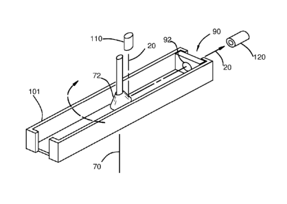
[0012] Figures 1 a and 1 b illustrate a test cell 90 including a cavity 91
according to the invention. Figure 1 b is a cross section view of the cell 90
shown in
Figure 1 a (through the center of the cavity 91). Before filling the cell 90,
it is
important that powder material placed in the cell 90 be free from lumps. The
material is preferably prepared by gently pushing the bulk material through a
sieve
with mesh size three to ten times that of the largest particle in the powder,
and the
sieved material collected. This has the effect of breaking the lumps and soft
agglomerates that may be present in the bulk powder due to caking or other
time
storage effects.
[0013] The cell 90 consists of a conical hole or cavity 91 formed in a body of
metal 80. The cavity 91 has a top outlet 92 having a diameter of dimension Dt.
For
many applications, a diameter dimension Dt of 6.35 millimeters (1 /4 inch)
will be
6
CA 02774496 2012-02-17
WO 2011/028387 PCT/US2010/045265
useful. The cavity 91 includes a bottom outlet 93 with a smaller diameter
dimension
Db that is 1 /3 to 1 /2 of the top diameter dimension Dt. The cavity 91 has a
height Ht
of about 70 percent of the top outlet diameter Dt. The cavity 91 has a conical
center
axis 95.
[0014] Retaining plates 81, 82 hold material in the cell 90 after the cavity
91
is filled. Filling the cavity 90 may be accomplished by placing the bottom
plate 82
against and covering the bottom outlet 93 and gently scooping bulk powder into
the
cell 90. Excess material should be scraped off level with the cell top outlet
92, and
the upper plate 81 positioned to cover the top outlet 92. The weight Wt of
material in
the cell 90 is measured using an external scale accurate to 0.001 grams.
[0015] The material in the cell 90 is then consolidated by placing the cell
assembly 100 (consisting of the cell 90 and covers 81, 82) into a rotation arm
101,
as shown in Figure 2, to enable spinning the cell about an axis of rotation
70. For
this purpose, the arm 101 may be connected to a conventional motor 73 capable
of
spinning at high speeds, typically 2,000 to 10,000 RPM (revolutions per
minute).
The cell is positioned at a distance R from the axis of rotation 70 with the
top outlet
92 facing respectively inward and the cavity enter axis 95 perpendicular to
the axis
of rotation 70 (the top cover 81 is partially cut away in Figure 2 to display
the top
opening 92). The arm 101 is rotated slowly, then increasing speed to a
prescribed
speed (RPMcomp) and then maintained at that speed for a prescribed amount of
time. The speed is measured preferably by a non-contact tachometer 74. The
motor 73 and tachometer 74 are shown schematically, and the particular
appropriate
selection, mounting, and operation of these devices will be clear to one
skilled in
these devices.
[0016] The centrifugal (outward) forces caused by rotation of the bulk mass
at high speed in a confined geometry cause the material to consolidate and
develop
stresses within the powder as discussed above.
7
CA 02774496 2012-02-17
WO 2011/028387 PCT/US2010/045265
The consolidation stresses (Sigma) can be calculated by the following
equation:
Sigma = 2 x (2?r x RPMComp)2 x R x Density x Ht
Where Density is a mass density with appropriate units and the remaining
parameters are as described above. This equation can be used to determine the
prescribed RPMcomp for the purposes of testing for a stress state in a
particular
application of interest where strength data for the powder is useful. It will
be obvious
to one skilled in the art that useful prescribed parameters may vary with
powder
characteristics as well as environmental characteristics.
[0017] After consolidation, the top and bottom retaining plates 81, 82 are
removed from the cell 90. With the plates 81, 82 removed, the material is free
to
flow from the outlet once acceleration force is again applied to the powder.
If the
material possesses strength as a consequence of consolidation induced
stresses,
the powder will arch over the conical outlet 93 and will not fall out when at
rest.
[0018] As shown in Figure 3, a light source 110 is configured to direct light
20 at the cavity 91. A photosensitive sensor 120 is located on the opposite
side of
the cell 90 and in line with the bottom opening 93 such as to receive the
light 20 if
passing through the cavity 91. After consolidation, the material in the cavity
91
blocks the light 20. Thus, light 20 impinging on the sensor 120 indicates that
the
cavity is no longer blocked by material. In the embodiment shown, the light is
reflected for convenience from a conical surface 72 attached to the rotation
arm 101
to align the light 20 with the cavity, while allowing the light source 110 to
be distant.
[0019] During testing for strength, the light 20 is maintained. The cell 90 is
then rotated at ever increasing speeds until the forces and stress levels
generated
by centrifugal acceleration overcome the strength of the bulk material and
force
material through the outlet 93. When this occurs, the light 20 passes through
the
outlet 93 to be detected by the photosensitive sensor 120, indicating failure
of the
8
CA 02774496 2012-02-17
WO 2011/028387 PCT/US2010/045265
cohesive arch in the test cell. The rotational speed at which the light first
appears
through the cell outlet 93 is recorded as the failure rotation speed
(RPMfail). This
value is used to compute the bulk strength of the material. The failure
stresses can
be computed to determine the bulk cohesive strength of the material sample.
[0020] The bulk unconfined yield strength (Strength) are calculated from the
equation shown below.
Strength = (2,t2Dt2R x Density x RPMfa,l2) l (Db x cos o)
Where 0 (phi) is the conventional internal angle of friction which can be
taken as
approximately 30 degrees for most materials and circumstances. If a more
accurate
value for angle of friction is known in any particular instance, it may be
applied in the
equation.
[0021 ] The particular design of the rotation arm 101 and structures
supporting the cell 90, light source 110 and sensor 120 and the reflective
elements
directing the light 20 are not critical and various alternatives will become
clear to
those skilled in the art to satisfy the objectives defined herein. The
essential parts
to carry out the inventive methods within this particular embodiment are: a
means of
imposing a compaction stress on the bulk material using centrifugal forces, a
means
of removing confining plates from the cell, a means of imposing a controlled
force to
fail an arched material by using centrifugal forces, and a means of
recognizing the
onset of failure by passing a light signal through the cell. Alternative
devices and
methods for satisfying the inventive concepts are contemplated and will be
obvious
to those skilled in the art.
[0022] Various other configurations of light sources and sensors and light
paths are contemplated and will be obvious to accomplish the same desired
functions as the configuration shown. It should be noted that with the
illustrated
configuration, the sensor 120 may be independently mounted or fixed to the arm
9
CA 02774496 2012-02-17
WO 2011/028387 PCT/US2010/045265
101. If independent, the potential delay from the powder failure to light
detection by
the sensor 120 will not alter the results as there will be no significant
change in
speed in the interim.
[0023] Based on the embodiment shown, it will be obvious that the applied
acceleration forces may be generated in other ways, although rotational
movement
is most convenient in most test settings. Likewise, alternative devices and
methods
of covering and exposing the cavity outlets may be used in substitution of the
retaining plates 81, 82 while providing the same function.
[0024] All of these devices and steps may be controlled by a computer. This
method could be automated, making it user friendly and technician resistant.
The
parts of this process that lend themselves to computer automation are control
of the
motors, rotational speed measurement, failure light trigger, environmental
control,
and calculation of the strength and consolidation pressure. This could be
implemented using a laptop computer, simple data acquisition board, and a
motor
driver board that can accept a voltage input signal. The filling of the test
cell and the
removal of the retaining plates are best done manually. The footprint for this
fully
automated device could easily fit on a bench top.
[0025] For the most part, the elements in the patent are sequential in nature.
Sample preparation should precede filling the cell, and consolidation must
always
precede testing the material to failure. However, there are some cases where
preparing the sample could be skipped as part of the process. The mode of
measuring the rotational speed generally includes a non-contact form of
measurement. This could include reflectance methods directed toward the shaft,
or
monitoring proximity sensors placed near the rotating arm. In another
embodiment,
the detected light that signals failure is used as a trigger to observe and
measure
rotational speed.
[0026] The light source 110 can be any (monochromatic, laser, or
CA 02774496 2012-02-17
WO 2011/028387 PCT/US2010/045265
multi-frequency) source with sufficient power to be observed either visually
or with a
photosensitive sensor capable of sensing 10,000 hertz signals. The method of
directing the light source through the cell as described above uses a
reflecting
surface on of a portion of the test cell rotation arm. However, in other
embodiments,
the mode of directing the light through the cell may use any set of reflective
surfaces
which eventually direct the light source through the cell either forward or
backward.
[0027] The inventive test methods could include conditioning the
environment (temperature or relative humidity) to a prescribed
temperature/humidity
profile during the consolidation phase of the test, thereby allowing the
tester to
mimic actual process conditions.
11