Note: Descriptions are shown in the official language in which they were submitted.
CA 02774521 2012-04-19
EFFICIENT LUBRICANT TREATMENT FOR RADIAL ENGINE
TECHNICAL FIELD
[0001] This application incorporates the contents of US Patent
Application 13/072,696
filed March 26, 2011.
[0002] The present disclosure relates to an improved radial power
generation fluid
dynamic lubrication system. Specifically, a lubricant system for improved
cooling and flow of
the lubricant within a radial engine is disclosed.
BACKGROUND
[0003] Radial engines have been commonly used in a variety of
applications involving
transportation. Radial engines are generally externally air-cooled with a
remote, external
lubricant reservoir tank and cooler. The lubricant generally flows in a
continuous closed loop
through the cooler, tank and directly back to the internal components of the
engine. A radial
engine generally has a centrally located crankshaft and a master-and-
articulating rod assembly.
The rod assembly includes a master rod that is attached directly to the
crankshaft, and a plurality
of rods attached to the master rod and disposed in a radial relationship about
the crankshaft. The
rods are disposed to engage the crankshaft such that there is correspondence
between the rotation
of the crankshaft and the reciprocating motion of a plurality of pistons
pinned to the rods and
positioned within a plurality of corresponding cylinders. Generally, lubricant
flows into the
engine through the crankshaft and non-integral lifter galley and drains out
through the crankcase
to the cooler and tank.
[0004] The master-and-articulating rod assembly generally includes a
master/main
bearing that is positioned between the crankshaft and the master rod
connection. The master
bearing supports the master-and-articulating rod assembly on the crankshaft.
Previous radial
engines have been plagued with fatigue and wear issues. Overheating of the
lubricant is also
problematic and can ultimately result in premature failure of the bearing and
rotating assembly.
[0005] Therefore, a need exists for an improved lubrication system to
prevent premature
failure of the rotating assembly, as well as to minimize maintenance costs by
increasing the Time
Between Overhauls (TBO).
1
CA 02774521 2012-04-19
SUMMARY
[0006] An engine lubrication device is disclosed. The device may include
at least one
lubricant supply pump, a crankcase having a first cavity and a second cavity,
a first flow path
extending through at least one master rod of a rotating assembly, a second
flow path extending
internally through at least one wall of the crankcase, and at least one
scupper extending into the
first cavity and fluidly connecting the first cavity with the second cavity.
The lubricant may be
supplied from the at least one lubricant supply pump, and through the first
flow path exiting into
the first cavity.
BRIEF DESCRIPTION OF THE DRAWINGS
[0007] While the claims are not limited to the illustrated examples, an
appreciation of
various aspects is best gained through a discussion of various examples
thereof. Referring now
to the drawings, illustrative examples are shown in detail. Although the
drawings represent the
various examples, the drawings are not necessarily to scale and certain
features may be
exaggerated to better illustrate and explain an innovative aspect of an
example. Further, the
examples described herein are not intended to be exhaustive or otherwise
limiting or restricting
to the precise form and configuration shown in the drawings and disclosed in
the following
detailed description. Exemplary illustrations of the present invention are
described in detail by
referring to the drawings as follows.
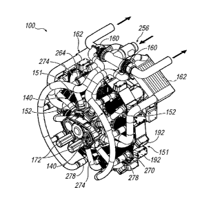
[0008] FIG. 1 illustrates a perspective view of an exemplary radial power-
generation
unit/radial engine with associated engine components installed;
[0009] FIG. 2 illustrates a perspective view of an exemplary radial
engine with a cylinder
head and associated components removed;
[0010] FIG. 3A illustrates a rear view of an exemplary radial engine
lifter side of a radial
engine crankcase with a single cylinder assembly installed;
[0011] FIG. 3B illustrates partial view of the cylinder in FIG. 3A
attached to the
crankcase with a cut-away of a hydraulic lifter, lubricant galley line and
crankcase lifter boss;
2
CA 02774521 2012-04-19
[0012] FIG. 3C illustrates a detailed view of FIG. 3B, demonstrating the
relationship and
placement of the hydraulic lifter, crankcase lifter boss and lubricant galley
line;
[0013] FIGS. 4A and 4B illustrates front and rear views of an exemplary
cylinder head
having lubricant drain back apertures;
[0014] FIG. 5 illustrates an exemplary push rod with each end in partial
section
demonstrating the fluid passage extending longitudinally through the push rod;
[0015] FIGS 6A ¨ 6C illustrate an exemplary rocker arm positioned on a
cylinder head,
the rocker arm includes a lubricant passageway for directing fluid;
[0016] FIG. 7 illustrates an exemplary perspective view of a radial
engine rotating
assembly positioned in a sectioned crankcase with cylinder sleeves positioned
on the crankcase;
[0017] FIG. 8A illustrates an end view of an exemplary crankshaft
mounting system and
counter weight boat placement;
[0018] FIG. 8B illustrates a side view of the exemplary crankshaft of
FIG. 8A sectioned
along a longitudinal centerline and a lubricant path through the crankshaft;
[0019] FIG. 9 illustrates a front view of an exemplary cross-sectioned
rotating assembly
configured in a sectioned crankcase;
[0020] FIGS. 10A ¨ 10E illustrates a cross-sectional view of the rotating
assembly and
the connection of the link rods to the master rod, as well as detailed views
the lubricant paths of
each rod;
[0021] FIG. 11A illustrates a front view of an exemplary master rod;
[0022] FIG. 11B illustrates a cross-sectional view of the exemplary
master rod of FIG.
11A and the master rods lubricant flow path;
[0023] FIG. 12A illustrates a front view of an exemplary link rod;
3
CA 02774521 2012-04-19
[0024] FIG. 12B illustrates a cross-sectional view of the exemplary link
rod of FIG. 12A
and the link rods lubricant flow path;
[0025] FIG. 13A illustrates an exemplary view of a crankcase configured
with a plurality
of scuppers positioned on an interior wall of the crankcase that separates a
crankcase cavity from
a lifter cavity;
[0026] FIG. 13B illustrates an exemplary detailed view of the scuppers of
FIG. 13A;
[0027] FIG. 14A illustrates a partial view of the exemplary wall dividing
the crankcase
cavity from the lifter cavity and a sectioned scupper;
[0028] FIG. 14B illustrates an exemplary detailed view the sectioned
scupper of FIG.
14A and the flow path of lubricant from the crankcase cavity to the lifter
cavity;
[0029] FIG. 15 illustrates an exemplary radial engine general lubrication
system;
[0030] FIG. 16 illustrates an exemplary flow path and associated
components of the
exemplary general lubrication system; and
[0031] FIG. 17 illustrates an exemplary power generation set having a
radial power-
generation unit operably connected to a generator and associated equipment.
DETAILED DESCRIPTION
[0032] Referring now to the discussion that follows and also to the
drawings, illustrative
approaches to the disclosed apparatuses and methods are shown in detail.
Although the drawings
represent some possible approaches, the drawings are not necessarily to scale
and certain features
may be exaggerated, removed, or partially sectioned to better illustrate and
explain the disclosed
device. Further, the descriptions set forth herein are not intended to be
exhaustive or otherwise
limit or restrict the claims to the precise forms and configurations shown in
the drawings and
disclosed in the following detailed description.
4
CA 02774521 2012-04-19
[0033] A lubrication system for a radial engine is disclosed. For
purposes of clarity, a
radial engine, configured as a power generation unit with an associated
electrical generator, will
be described. However, it should be known that the disclosed improved
lubrication system may
be utilized in various radial engine applications, such as, but not limited
to, fixed wing aircraft,
rotary aircraft, automobiles, motorcycles, boats and other applicable uses of
a radial engine.
Additionally, the disclosed lubricant system may be utilized in various
orientations and
configurations, such as, but not limited to, vertical, horizontal and other
various angled positions
as would be suitable for a radial engine.
[0034] The improved lubricant system may include an improved external
supply and
scavenge/recirculation system, including an electronic lubricant pump with a
plurality of valves
and lubricant feed lines entering the radial engine to ensure generally
instantaneous lubricant
pressure. The lubricant pump may be used to prime and pressurize the system to
provide
lubricant to the rotating assembly prior to and during start-up. A temperature
controlled
lubricant cooler bypass valve may be used to improve efficiency and power
generation at start-
up. The external recirculation portion may include at least one scavenge pump
for the removal
of the lubricant from the internal areas of the radial engine after shutdown
to avoid flooding the
cylinders.
[0035] As is discussed in detail below, the lubricant pump directly
connects the external
supply system with the internal flow paths within a rotating assembly.
Specifically, a flow path
extends from the pump through the crankshaft. The crankshaft may be fluidly
connected to the
master connecting rod, which may be fluidly connected via an internal flow
path to the link rods
at a first end. Both the master connecting rod and the link rods include
longitudinally extending
internal flow paths that extend from the first end to a second end. The second
ends are rotatively
connected to an underside of a piston through a wrist pin. The second ends
further include piston
sprayer nozzles that provide increased and directed flow to the underside of
the pistons.
[0036] An additional flow path may be created through the lubricant pump
that may be
fluidly connected to the lubricant galley lines. The lubricant galley lines
are internal to the
crankcase and provide a lower pressure lubricant supply to a hydraulic lifter.
The hydraulic lifter
CA 02774521 2012-04-19
may be fluidly connected to a rocker arm through a hollow push rod. The hollow
push rod
transfers both linear motion and lubricant to the rocker arm from the
hydraulic lifter. The rocker
arm diverts the lubricant to the moving parts within the rocker box attached
to the head which
houses the intake and exhaust systems, as well as a spark plug and may be
attached to a cylinder
sleeve to create a combustion chamber. The intake and exhaust system within
the head includes
an intake valve and an exhaust valve that may be isolated from the lubricant
through a valve
shaft seal. The head also includes a plurality of lubricant drain back
apertures to direct the used
lubricant either to an adjacent cylinder assembly, to a sump or to the cam and
lifter side of the
crankcase and gearbox. The crankcase may be fluidly sealed during operation
and transfers
lubricant through lubricant lines and lubricant passageways that may be
fluidly connected to at
least one pump.
100371 During operation of the radial engine, the rotating assembly
includes a crankshaft,
master connecting rod, link connecting rods and pistons. As discussed above,
the lubricant flows
through these components and may be released or drains into the crankcase. As
the rotating
assembly rotates, the lubricant may be forced radially outward through
centrifugal forces, which
result in the lubricant being churned and aerated to a point where the
lubricant may be broken
down or sheared, resulting in overheating. One element used to reduce churning
and aeration
may be a small louver, or scupper, that projects inwardly towards the rotating
assembly and
away from the wall separating the crankcase internal area from the cam and
lifter side of the
crankcase.
100381 As is further discussed below, the scuppers work to deflect the
lubricant, that may
be flowing about the crankcase, and pull it into the lifter area. This action
may reduce windage
and aeration of the lubricant, which may lead to better operating quality and
conditions, as well
as, reduced heat generation. The deflection and removal may allow the
lubricant to be
scavenged via a scavenging pump that pulls the lubricant out of the crankcase
and into the
external scavenging system for cooling, storage or reintroduction into the
flow path of the radial
engine. The removal of the lubricant may help to reduce the volume of
lubricant required in the
crankcase as well as reducing the potential of flooding in the lower
cylinders. By creating a flow
path from the crankcase to the bell housing or lifter side of the case, the
scuppers create an
6
CA 02774521 2012-04-19
additional path for venting. Additionally, by continually injecting cool
treated lubricant back
into the process, the lubricant may help to prevent premature failure and
extend the life of the
rotating assembly.
100391 Additionally, upon shutdown of the radial engine, the scavenging
portion of the
external lubricant treatment system begins to draw the remaining lubricant out
of both sides of
the crankcase. This may be done to eliminate any leftover lubricant to ensure
the sump is dry
after shutdown, minimizing or eliminating any lubricant migration into the
combustion chamber
of the lowest cylinders.
[0040] Turning to the illustrative embodiments, FIG. 1 is a perspective
view of an
exemplary radial power-generation unit 100. Radial power-generation unit 100
is a piston-
driven radial engine structured and arranged to produce at least one output of
rotary power from
the combustion of at least one fuel. The radial engine 100 may include a
plurality of cylinders
140 interconnected with and extending into a two-part crankcase 186. The
cylinders may
include spacing of approximately 40 degrees from each cylinder 140 center. It
should be known
that other spacing arrangements may be used depending on the application. The
crankcase 186
houses an internal rotating assembly 153, (see FIGS. 2 and 7) and may provide
a mounting point
for each cylinder 140 and any associated components, which will be discussed
in greater detail
below.
[0041] As illustrated, the cylinder heads 151 may include intake ports
264 and exhaust
ports 270. The intake ports 264 may be fluidly connected to a gas air mixer
256 through at least
one intake tube 274. The exhaust ports 270 may be fluidly connected to a
muffler or exhaust
silencer 214 (see FIG. 17) through at least one exhaust tube 278. The intake
tubing 274 and
exhaust tubing 278 may be interconnected through at least one turbocharger 160
and integrated
intercooler 162 depending on the application. The cylinder heads 151 may
include rocker arm
covers 192 affixed to a top surface of the head 151 to aid in the reduction of
foreign debris
entering the rocker area as well as to avoid lubricant 120 leaks.
[0042] Turning to FIGS. 2¨ 3C, a portion of the exemplary internal
rotating assembly
153 may be seen extending from the crankcase 186. Specifically, a plurality of
pistons 156 and a
7
CA 02774521 2012-04-19
plurality of link rods 170 are protruding from the crankcase internal cavity
190. The crankcase
186 may include at least one machinable boss 180. Each boss 180 may be formed
directly in the
crankcase 186 and may be configured to receive a hydraulic lifter 164, at
least one lifter 164 per
cylinder 140. The crankcase 186 may be constructed from any rigid material,
such as, but not
limited to cast ductile/nodular iron, aluminum, steel and composite. However,
regardless of the
material and process used for constructing the crankcase 186, at least one
integrated lubricant
galley line 168 may be formed internally to the crankcase 186 walls 188.
Additionally, an access
area (not shown) may be machined within the crankcase 186 to allow for
cleaning and inspection
of the lubricant galley line 168. The integral galley line 168 eliminates the
need for a separate
cast and precision machined internal lifter ring (not shown).
[0043] The integrated galley line 168 may provide lubrication and
hydraulic pressure
from at least one pump 172 to the hydraulic lifters 164. The lubricant 120
supplied to the
lubricant galley line 168 may be maintained at approximately 30 ¨ 80 PSI and
have a flow rate of
approximately 6¨ 11 GPM while the lubricant 120 that may be supplied through
the at least one
pump 172 that may be fluidly connected to a crankshaft 210 (see FIGS. 7¨ 8B)
of the internal
rotating assembly 153 may be maintained over a pressure range of approximately
90¨ 125 PSI
with a flow rate of approximately 6¨ 14 GPM. Hydraulic lifters 164 provide
valve train noise
reduction, as well as reduce the wear associated with the valve train (not
shown) while providing
a close to constant valve lash (not shown) at all operating temperature
ranges. However, it
should be known that alternative galley lines 168 may be provided, such as,
but not limited to,
external lines or lines internal to the crankcase 186 internal cavity 190 and
not integral to the
crankcase 186.
[0044] FIGS. 3A ¨ 3C further illustrates, an exemplary arrangement of the
cylinder 140
with the head 151, finned cylinder barrel 152 and crankcase 186
interconnected. Specifically, a
single cylinder barrel 152 and attached cylinder head 151 may be affixed to
the crankcase 186.
The cylinders 140 may be affixed radially around an outer surface of the
crankcase 186, utilizing
at least one attachment device, such as, but not limited to a bolt, threaded
rod or nut. When the
head 151 and cylinder barrel 152 are interconnected, a seal system (not shown)
compresses
between the two to eliminate any contamination or loss of fluid between the
connection of the
8
CA 02774521 2012-04-19
barrel 152 and the head 151. The seal system may be integral to at least one
of the head 151 or
barrel 152 and may be constructed from a compressible material, such as, but
not limited to,
copper, brass, aluminum, and bronze or other compressible material or machined
feature.
[0045] As illustrated, the crankcase 186 includes the hydraulic lifter
164 positioned in the
boss 180 on the lifter/cam side of the crankcase 186. The lifter 164 may be
activated by an
internally rotating cam (not shown) rotatively connected to the crankshaft
210. The cam may
travel along an outer circumference of the internal cavity 190 to engage the
lifter 164, resulting
in activation of a pushrod 222 (see FIG. 5). The pushrod 222 may be housed
within a pushrod
tube 290 to operatively and fluidly connect the hydraulic lifter 164 with the
rocker arm 224.
Generally, the rocker arms 224 are enclosed by rocker arm covers 192 affixed
to the head 151.
In operation, lubricant 120 may be provided from a reservoir 276, utilizing
the pump 172, and
through the galley line 168 to the hydraulic lifter 164. The hydraulic lifter
164 may be fluidly
connected to the pushrod 222, which provides lubricant 120 to the rocker arms
224 through a
longitudinally extending channel 226. Once the lubricant 120 reaches the
rocker arms 224, it
may flow back into the crankcase internal cavity 190 through a primary
lubricant drain back
aperture 202 and down the pushrod tube 290 (see FIG. 4A). Alternatively, the
lubricant 120 may
flow through a secondary lubricant drain back aperture 204 and into an
exteriorly mounted tube
(not shown) that may be linked between each head 151 (see FIG. 4B). The
multiple drain back
apertures 202, 204 allow for the effective removal of lubricant 120 when the
radial engine 100
may be in various positions, reducing the possibility of flooding the rocker
area in the head 151.
[0046] Returning to FIG. 3B, the cylinder barrel 152 includes a skirt
section 206 that,
when the barrel 152 may be attached to the crankcase 186, extends down into
the internal cavity
190 within the crankcase 186. This extra length into the crankcase 186 aids in
the reduction of
aeration of the lubricant 120 as well as directs the flow of lubricant into
the base of the crankcase
186.
[0047] Turning to FIGS. 6A ¨ 6C, the rocker arm 224 may be pressure fed
from the
hydraulic lifter 164 through the hollow pushrod 222. The lubricant 120 may be
directed through
a channel 228 within the rocker arm 224 and may be sprayed at a spring (not
shown).
9
CA 02774521 2012-04-19
Additionally, the head 151 includes the use of valve seals 232 to reduce
lubricant 120
consumption due to drainback along an intake or exhaust valve shaft (not
shown) into the
combustion chamber (not shown).
[0048] FIG. 7 illustrates an exemplary cut away view of the radial engine
100.
Specifically, the view provides an exemplary arrangement of the internal
rotating assembly 153.
The rotating assembly 153 may include a crankshaft 210 and a master connecting
rod 158 having
a first end 230 and a second end 234; the first end 230 may be rotatively
connected to the
crankshaft 210 and rotatively connected to a piston 156 at the second end 234.
Additionally, at
least one connecting link rod 170, having a first end 230 and a second end
234, may be rotatively
connected to the master connecting rod 158 at an outer periphery of the first
end 230 and
rotatively connected at the second end 234 to a piston 156.
[0049] As specifically illustrated in FIGS. 7 and 8, the crankshaft 210
may be a split-
clamp type, thus allowing master rod 158 to be configured as a single
continuous design. The
master and articulating rod assembly 153 may be assembled with a main bearing
238 that may be
positioned within the first end 230 of the master rod 158 prior to sliding the
master and
articulating rod assembly onto a crank pin 236. As discussed above, the link
rods 170 may be
positioned on the outer periphery of the master rod 158 first end 230, such
that the link rods 170
are configured to rotate. After the rods 170 are all assembled on the master
rod 158, the first end
230 may be slidingly engaged on the crank pin 236. It should be noted that the
crank pin 236
may include several features to improve the longevity of the main bearing 238.
Specifically, the
surface includes a micro-polish surface finish with a maximum allowable taper
across the crank
pin 236 surface which may be approximately 0.0025 mm ¨ 0.015 mm; a maximum
allowable
surface change may be approximately 0.001 mm ¨ 0.005 mm within 100 of
rotation; a maximum
of approximately 7-20 lobe changes are allowed with no height changes of more
than
approximately 0.0010 mm ¨ 0.0020 mm; and a maximum allowable total indicated
reading
(T.I.R.) may be approximately 0.0025 ¨ 0.0075. Additionally, it should be
known that the
Rockwell Hardness at the crank pin 236 should be approximately RC 55 ¨ 63,
with a case
hardness of approximately 1 to 4 mm and a core Brinell Hardness of
approximately HBS 280 ¨
CA 02774521 2012-04-19
340. Additionally, the crank pin 236 includes an increased diameter range of
approximately 82
mm to 97 mm with a length range of approximately 73 mm to 84 mm.
[0050] Once the master rod 158 may be positioned on the crank pin 236,
the crankshaft
face 237 and associated bull nose counter weight boats 250 are affixed to the
crank pin 236.
Specifically, the crankshaft face 237 may be clamped down by threadingly
engaging the bolt to
engage the faces 237 around the crank pin 236. The counter weight boats 250
may be loosely
attached to the crankshaft faces 237 using a pin and bolt system. This loose
fit allows the
counter weight boats 250 to move and remain balanced during pendulum harmonic
dampener
rotation of the radial engine 100 components. The counter weight boats 250 may
be made of
cast iron or other known material for constructing counter weights. The boats
250 have been
machined to a bull nose configuration, which includes fillets and rounds,
providing a smooth
outer surface thereby removing any sharp or blunt edges from the counter
weight boats 250. The
smooth and rounded edges help to minimize any aeration or shearing of the
lubricant 120 during
normal operation of the radial engine 100. The bull nose configuration allows
the counter weight
boat 250 to essentially float through the liquid as the rotating assembly 153
moves radially
through the engine cycle.
[0051] In order to provide lubricant 120 to the rotating assembly 153,
and the other
moving parts within the radial engine 100, the crankshaft 210 may be
configured with an internal
lubricant passageway 243. Additionally, the master rod 158 and link rod 170
may also be
configured with corresponding lubricant passageways 253, 255 to mate with the
crankshaft's 210
lubricant passageways 243. As specifically illustrated in FIG. 8A, the
crankshaft's 210 lubricant
passageway 243 may extend longitudinally through a shaft portion 254 of the
removable
crankshaft faces 237. The lubricant passageway 243 may extend to and connect
with a
corresponding lubricant passageway 243' within the crank pin 236. The
crankshaft's
passageway 243 may terminate at a plurality of lubricant 120 discharge
apertures 245 on the
crank pin surface 239. Additionally, the master rod 158 and link rods 170
lubricant passageways
253, 255 are fluidly connected to the crank pin 236 lubricant 120 discharge
apertures 245.
Careful attention should be paid when positioning the master rod 158 onto the
crank pin 236 to
11
CA 02774521 2012-04-19
ensure full engagement of the main bearing 238 and alignment of the
passageways 243, 253 to
correspond to one another.
[0052] As illustrated in FIGS. 9¨ 12B, the rotating assembly 153 may be
fluidly
connected at each contact point at the ends and crank pin 230, 234, 236. This
fluid connection at
first end 230 and the crank pin 236 may be the main entryway into the master
rod 158 and link
rod 170 to provide fluid to an underside area of the piston 156. This may be
best seen at FIG.
10B, where the connection between the master rod 158, the crank pin 236 and
the link rods 170
are all fluidly connected through the various lubricant passageways 243, 245,
253, 255.
Specifically, the lubricant 120 will enter the master rod 158 at passage 253,
flow longitudinally
through the master rod 158, and exit at the second end 234 on the under side
of the piston 156.
Additionally, lubricant 120 may flow through the lubricant passageway 253 and
exit into the
adjacent passageway 255 on each link rod to provide each second end 230 and
piston 156 with
lubricant 120. As discussed previously, the lubricant 120 entering passageway
243 may be
pressurized due to the use of pump 172. The pressure feeding of lubricant 120
to the first and
second ends 230, 234 dramatically reduces the risk of bearing failure.
Pressure feeding allows
lubricant 120 to penetrate the second end 234 at a wrist pin (not shown) used
to connect the
piston 156 to the master and link connecting rods 158, 170. Additionally, a
piston sprayer 258
(FIG. 10C) may be utilized at the exit side or second end 234 of the lubricant
passageways 253,
255 extending longitudinally through the master and link rods 158, 170 and
exiting at the second
end 234. The piston sprayer 258 may help to reduce the likely hood of pre-
ignition and
detonation by cooling a crown or top surface of the piston, while further
adding to the longevity
of the pistons and rings (not shown).
[0053] During operation of the radial engine 100, rotating assembly 153
may be
pressurized with lubricant 120 to prolong the life of the radial engine 100.
As discussed above,
the lubricant 120 flows through rotating assemblies' 153 components to
ultimately eject out of
the underside of each piston 156. Once the lubricant 120 is released it
becomes a free flowing
mass that may be forced radially outward or flung throughout the crankcase
internal cavity 190.
The rotational forces present within the cavity 190 may prevent the lubricant
120 from naturally
flowing downward to at least one drain aperture (not shown) in the base of the
crankcase 186.
12
CA 02774521 2012-04-19
Thus, as the rotating assembly rotates the lubricant 120 may be churned and
aerated to a point
where the lubricant 120 may be broken down or sheared resulting in
overheating. One element
used to combat such an outcome is a small louver or scupper 194.
100541 Specifically turning to FIGS. 14A and 14B, an exemplary scupper
194 is
illustrated. At least one scupper 194 may be formed directly in the wall 188
of the crankcase
186. When formed, the scupper 194 may be a solid continuous part of the wall
188 and may go
through a machining process to create a scoop portion 182 that may act as an
access or pathway
providing fluid communication between the two cavities 190, 184 of the
crankcase 186. The
scupper 194 projects inwardly towards the rotating assembly 153 into the
crankcase internal
cavity 190 and away from the wall 188 separating the crankcase internal cavity
190 from the cam
and lifter side cavity 184 of the crankcase 186. The scupper 194 works to
deflect the lubricant
120, that may be flowing about the crankcase 186, into the lifter cavity 184
where gravity allows
the lubricant 120 to drain down properly. This action may reduce windage and
aeration of the
lubricant 120, which may lead to better operating quality and conditions, as
well as, reduced heat
generation. Deflection of the lubricant 120 to be scavenged via a scavenging
pump 320 that
pulls the lubricant 120 out of the crankcase area cavities 190, 184 and into
the external lubricant
filtration system 318 for cooling, storage or reintroduction into the flow
path of the radial engine
100. By creating a flow path from the crankcase internal cavity 190 to the
lifter side cavity 184
of the crankcase 186, the scuppers 194 create an additional path for venting
gases within the
crankcase 186. The removal of the lubricant 120 may help to reduce the volume
of lubricant 120
required in the crankcase as well as reducing the potential of flooding in the
lower cylinders.
Additionally, by continually injecting cool treated lubricant 120 back into
the process the
lubricant 120 may help to prevent premature failure and extend the life of the
rotating assembly.
100551 Turning to FIG. 15 illustrates an exemplary arrangement of an
external lubricant
filtration system 318 is disclosed. The external lubricant filtration system
318 may provide a
path and storage of lubricant 120 for secondary cooling of the exemplary
radial engine 100. The
external lubricant filtration system 318 may be part of a general lubrication
system that may also
include the internal lubricant flow system as discussed above, which includes
the lubricant galley
flow path and the rotating assembly 153 flow path.
13
CA 02774521 2012-04-19
[0056] The external lubricant filtration system 318 may be configured
with a lubricant
pump pressure section 320 and a lubricant pump scavenger section 322. The
external lubricant
filtration system 318 may include a prime pump 324, at least one of a remotely-
mounted full-
flow lubrication filter 378, lubricant cooler 280, and lubricant reservoir
276, as shown. A
crankshaft lubricant feed check valve 326, a lifter valley check valve 328,
sump tank 330,
electric scavenge pump 332 and bypass valve 334 are included. The bypass valve
334 may be
temperature controlled valve to improve system efficiency and when not in use,
allows the
lubricant 120 to reach operating temperature faster, which in turn allows full
power generation
capability faster. Each component of the external lubricant filtration system
318 may be coupled
by a set of lubricant distribution lines 336 enabling fluid communication with
an engine-driven
lubricant circulation pump 172 of radial power-generation unit 100. Lubricant
filtration system
318 functions as an extension of the internal engine lubricating system of
radial engine 100,
which may include the pressure pump 320 and scavenging pump 322, lubricant
distribution lines
336, etc. Lubricant cooler 174 may include active cooling through at least one
motorized fan
338 operated by at least one of a 12-volt and a 24-volt direct current (DC)
source.
[0057] Upon shutdown of the radial engine 100, the scavenging portion 322
of the
external lubricant treatment system begins to draw the remaining lubricant 120
out of both
cavities 190, 184 of the crankcase 186. The removal of the lubricant 120 may
help to reduce the
volume of lubricant 120 required in the crankcase 186 during normal operation,
as well as
reducing the potential of flooding in the lower cylinders 140 prior to start-
up. The removal of
lubricant 120 helps to minimize any lubricant 120 migration into the
combustion chamber of the
lowest cylinders 140 after shutdown. Additionally, as discussed above, the
check valves 326,
328 help to eliminate lubricant 120 from leaking past the pumps 320, 332 and
into the crankcase
186.
[0058] An exemplary flow diagram of the general lubrication system 110 is
illustrated in
FIG. 16. The general lubrication system 110, illustrates the possible flow
path and components
that may be present within the system as well as the direct circuit path back
to the lubricant 120
reservoir. The general lubrication system 110 may also include a remote
predictive failure
monitoring device that allows an operator monitor the current conditions of
the radial engine
14
CA 02774521 2012-04-19
100. Specifically, the monitoring device may monitor the volume of lubricant
120 in the system
and the temperature of the lubricant 120 as it enters and leaves the radial
engine 100. The
monitoring device may also check the lubricant viscosity, cleanliness and the
current state of the
elements present within the lubricant 120, such as additive package, friction
modifiers and the
metal ions present within the lubricant 120. These conditions may indicate
when the lubricant
120 may need to be replaced or modified.
[0059] Turning to FIG. 17 the radial engine 100 is illustrated as a power
head configured
to provide rotary power to, and operationally coupled with, at least one
electrical generator 310.
This arrangement is merely exemplary, as the radial engine 100 may be
configured for a
multitude of uses, as discussed above.
[0060] Specifically, FIG. 17 illustrates an exemplary arrangement in the
form of a power
generation set 302. The power generation set 302 generally includes the radial
engine 100
coupled to and arranged directly forward of the electrical generator 310. The
power generation
set 302 generally includes an electrical control system (not shown), fan
cooling ducting 208, a
torque-transmission unit 212, an air intake 116, an external lubricant
filtration system 318 (see
FIG. 3), a fuel-delivery system 322 and exhaust silencer/muffler 214. The
radial engine 100 and
associated equipment may be affixed to a structural frame 240 for ease of
transporting. It should
be known that radial engine 100 may be additionally supported by a cradle (not
shown) having
vibration damping isolators (not shown) at a connection between the radial
engine 100 and the
structural frame 240. The isolators may be made of any known material having a
predetermined
rigid durometer for withstanding the load of the radial engine 100, as well as
a predetermined
shock absorbing durometer. The cradle may be configured to transfer vertical
loads, such as the
weight of the radial engine 100, in addition to torque loads generated by the
radial engine 100
during operation. The cradle and structural frame 240 may be made from any
known structural
material, such as, but not limited to steel, aluminum, iron and composite.
[0061] As discussed above, 17 illustrates fan cooling ducting 208.
Alternatively, under
certain applications, the fan cooling ducting 208 may not be economical or
feasible due to the
application of the system and where the footprint may be constrained. Where
the cooling
CA 02774521 2012-04-19
ducting 208 may be constrained, alternative cooling methods may be employed,
such as, but not
limited to, the use of liquid cooled heads and block assemblies. When using
liquid cooling, a
radiator (not shown) or the intercooler 162 may be utilized to cool the
liquid. However, as
illustrated, the use of an exemplary fan/rotor (not shown) arrangement may be
described in
greater detail below.
[0062] Specifically, cooling ducting 208 provides a source for the
primary radial engine
100 cooling. Air may be drawn across an auxiliary fan or rotor through the
cooling ducting 208
and across the plurality of cylinder heads 151. The fan/rotor may be
positioned axially either
forward or aft of the radial engine 100 to draw air across and around the
radial engine 100. The
fan/rotor may be configured as a plurality of rotary blades that are driven by
at least one of an
electric motor, a hydraulic motor or through a direct connection to the
internal rotating assembly
153 of the radial engine 100. The cylinder heads 151 and cylinder barrel 152
may include
cooling fins 154, to increase surface area for dissipating heat as air moves
about the outer surface
of the radial engine 100 and through at least one turbocharger 160 intercooler
162.
[0063] With regard to the processes, systems, methods, heuristics, etc.
described herein,
it should be understood that, although the steps of such processes, etc. have
been described as
occurring according to a certain ordered sequence, such processes could be
practiced with the
described steps performed in an order other than the order described herein.
It further should be
understood that certain steps could be performed simultaneously, that other
steps could be added,
or that certain steps described herein could be omitted. In other words, the
descriptions of
processes herein are provided for the purpose of illustrating certain
embodiments, and should in
no way be construed so as to limit the claimed invention.
[0064] Accordingly, it is to be understood that the above description is
intended to be
illustrative and not restrictive. Many embodiments and applications other than
the examples
provided would be upon reading the above description. The scope of the
invention should be
determined, not with reference to the above description, but should instead be
determined with
reference to the appended claims, along with the full scope of equivalents to
which such claims
are entitled. It is anticipated and intended that future developments will
occur in the arts
16
CA 02774521 2012-04-19
discussed herein, and that the disclosed systems and methods will be
incorporated into such
future embodiments. In sum, it should be understood that the invention is
capable of
modification and variation and is limited only by the following claims.
100651 All terms used in the claims are intended to be given their
broadest reasonable
constructions and their ordinary meanings as understood by those skilled in
the art unless an
explicit indication to the contrary in made herein. In particular, use of the
singular articles such
as "a," "the," "the," etc. should be read to recite one or more of the
indicated elements unless a
claim recites an explicit limitation to the contrary.
17