Note: Descriptions are shown in the official language in which they were submitted.
CA 02774687 2012-03-16
WO 2011/035074 PCT/US2010/049195
CO1-003-0009 1
MODULAR QUAD CELL E LE CTRO-ME CHAN I CAL
OZONE GENERATION DEVICE
Technical Field
This invention relates to a modular quad cell, electro-
mechanical ozone generator device and system. More
particularly, it relates to a highly-concentrated output
modular ozone generator system having four generator cells in
each modular ozone generator, which can be combined onto
trays forming a rack of ozone generators for providing a high
concentration, high output yield of liquid or air-cooled
ozone for a multitude of industrial, commercial and military
purposes.
Background Art
Modular ozone generator systems that can be combined to
form blocks of generators are known in the prior art. For
example, US Patent No. 6,599,486 to Bergstrom discloses an
ozone generator system in which a multitude of plate-type
ozone generators are arranged adjacent to each other in a
block. Each ozone generator comprises a chamber, adapted for
converting oxygen to ozone by a corona discharge, and each
chamber is provided with an inlet for oxygen or an oxygen-
rich gas and an outlet for ozone. The ozone generators are
arranged in a block module in which they are affixed by a
block rack. The block rack comprises an inlet port adapted
for introduction of oxygen gas, and an outlet port adapted
for discharge of ozone created through conversion within the
generators comprised in the block module. A multitude of
first conduits, each running between said inlet port and one
chamber inlet, and a multitude of second conduits, each
running between said outlet port and one chamber outlet, are
provided within said block rack. However, each modular ozone
CA 02774687 2012-03-16
WO 2011/035074 PCT/US2010/049195
CO1-003-0009 2
generator system of this prior art reference employs only a
single generator cell with only a single plasma pathway
within each module. Further, Bergstrom requires that the
flow path of each and every one of the ozone generators in
the block module be substantially the same. A micro-channel
network would not require such and would therefore be an
improvement over the prior art of a modular ozone generator
unit and/or system.
US Patent 6,994,832 also to Borgstrom discloses another
modular ozone generator system and claims priority to
Borgstrom's other earlier issued patent described above (the
'486 patent). This second Borgstrom reference discloses an
ozone generator system having a multitude of plate type ozone
generators arranged adjacent to each other in a block. Each
ozone generator includes a chamber, adapted for converting
oxygen to ozone by a corona discharge; each chamber is
provided with an inlet for oxygen or an oxygen-rich gas and
an outlet for ozone. The ozone generators are arranged in a
block module in which they are affixed by a block rack. The
block rack includes an inlet port adapted for introduction of
oxygen gas, and an outlet port adapted for discharge of ozone
created through conversion within the generators of the block
module. A multitude of first conduits, each running between
the inlet port and one chamber inlet, and a multitude of
second conduits, each running between the outlet port and one
chamber outlet, are provided within the block rack. The
conduits are arranged so that the flow paths and distance
between the inlet and outlet ports have the same length,
regardless of which generator the introduced gas passes
through, thereby achieving an even gas pressure and gas flow,
through parallel connection of the generators. However, as
in the other Bergstrom reference each modular generator only
3
contains a single ozone generator cell and each cell is only
a single ozone generating unit (see Fig. 1 of Borgstrom
'832). Further, this, nor the other Borgstrom reference
above, disclose, teach or suggest the use of an internal
liquid coolant micro-channel network juxtaposed to the ozone
generating discharge plates. Still further, this, nor the
other Borgstrom reference above disclose, teach or suggest
the use of an equalizing pressure means, such as spring
plates and Teflonmlocators, within the ozone cells to -
normalize and keep the pressure constant in each modular
generator. And this is critically needed in any modular
block ozone generation system and something that clearly
needs improvement upon over the Borgstrom inventions.
Finally, this Borgstrom invention requires that the
electronic unit be mounted on the block rack. This is a
. disadvantage as locally employed electronics within each
individual ozone generating cell would allow greater control
and would be a clear improvement over the prior art.
US Published Application No. 2005/0161318 to Arlemark
discloses a method and apparatus for improving the yield of
ozone gas in a closed ozone generator unit. In this closed
ozone generator unit, oxygen gas is transformed into ozone
gas by means of alternating current, the oxygen gas being
substantially pressurized before entry into the unit. The
unit is exposed to an external pressure substantially equal
to or higher than the pressure of the oxygen gas. This unit
employs two ceramic plates forming a closed space containing
a metal electrode, supplied with alternating current for
transforming supplied oxygen gas into ozone gas. The
generator unit may be submerged in water to act as a cooling
liquid and as a second pole;.a metal electrode within the
unit acts as a first pole. In this practical design the
CA 2774687 2020-02-05
CA 02774687 2012-03-16
WO 2011/035074 PCT/US2010/049195
CO1-003-0009 4
water has a pressure equal to or higher than the pressure of
the oxygen gas. This ozone generator system is considered
"water cooled" but it is a "wet cooled system and does not
disclose, suggest or teach the use of a liquid coolant system
employing a liquid micro-channel network formed on a section
layer positioned juxtaposed to the generator cell to
affectively cool the ozone being produced. Further, although
this reference discloses that four ozone generator assemblies
are arranged in a container, this reference does not
contemplate placing four individual ozone producing cells
within a single modular unit, wherein each module can then be
made part of a larger rack system of more than one module, to
form a cube or network of modules. Therefore, this prior art
reference fails in an area of great need.
US Patent No. 6,869,575 to Tabata et al. discloses a
small-sized ozonizer capable of generating highly
concentrated ozone with a high generating efficiency. The
ozonizer has a low voltage electrode that includes a disc-
shaped low voltage electrode main body facing a high voltage
electrode and an extension at one side of the low voltage
electrode main body. The extensions are laminated in layers
on a base via blocks and contain a coolant inlet portion for
supplying coolant to a coolant passage. Also included are a
coolant outlet portion for exhausting coolant from the
coolant passage and an ozone gas outlet portion for
exhausting ozone gas from the ozone gas passage pass through
the extensions and the blocks, respectively, in a laminating
direction of the discharge cells. Like Arlemark, or any
other prior art reference, Tabata et al. does not disclose,
suggest or teach placing four individual ozone producing
cells within a single modular unit, wherein each module can
then be made part of a rack. Further, although Tabata et al.
CA 02774687 2012-03-16
WO 2011/035074 PCT/US2010/049195
CO1-003-0009 5
speaks to coolant passages, it fails to disclose the use of a
liquid coolant plate or layer section mounted within a center
body framing element that is positioned juxtaposed to the
ozone generating cells of a modular ozone generation system,
of which the liquid coolant plate employs a micro-channel
network for passing a liquid coolant there through (i.e.,
liquid) to significantly reduce the temperature of the ozone
being produced there within. And therefore, improvement is
clearly needed.
US Patent No. 7,198,765 to Tabata et al. discloses a
flat plate laminate ozone generating apparatus including a
plurality of laminated plate-shaped high voltage electrodes
and low voltage electrodes between which an alternating
voltage is applied to produce a discharge and generate ozone
gas, and in particular, to an ozonizer which is an essential
portion of the flat plate laminate ozone generating apparatus
and which includes the high voltage electrodes and low
voltage electrodes and to which a gas containing oxygen is
supplied to generate ozone gas, and also in particular, to a
construction of the ozonizer which is thin, of a large
capacity and in which the number of components may be reduced
while also making the apparatus small in size. In one
embodiment Tabata '765 discloses that the ozone generating
apparatus of this invention has a plurality of ozonizers
employed in a single housing so that it may be an ozone
generating apparatus of further increased capacity, reduced
size and may manufactured and maintained at a reduced cost.
However, nowhere in this reference is it disclosed, suggested
or taught that the single ozonizer can be made to be a
modular unit, enclosing a multitude of ozone generating
cells, which can then be combined in a tray to form a rack.
Further, nowhere in this Tabata reference does it disclose,
CA 02774687 2012-03-16
WO 2011/035074 PCT/US2010/049195
CO1-003-0009 6
let alone teach or suggest, the use of a liquid coolant plate
that employs a micro-channel network system for passing a
liquid coolant there through (such as water) to significantly
reduce the temperature of the ozone being produced there
within. Further, in both of the above Tabata prior art
references the use of conductive film on a second electrode
is required. An ozone generating system not employing such
films is needed and so therefore, both of these Tabata
inventions clearly need to be improved.
US Patent No. 5,932,180 to Zhang et al. discloses a
reactive gas generator cell that includes a high voltage
assembly having a high voltage electrode plate and a low
voltage assembly having a low voltage electrode plate. Each
of the high and low voltage assemblies includes a cover plate
and a channel plate. A welded metallic seal may join the
high voltage assembly and the low voltage assembly to create
a permanently sealed chamber between the assemblies. A
refractory metal surface, which may be a tungsten surface, is
disposed on at least one of the low voltage electLode plate
and the high voltage electrode plate. A dielectric barrier
is disposed between the high voltage electrode plate and the
low voltage electrode plate. A discharge region for
confining a reactive gas is defined, at least in part, by the
refractory metal surface and a surface of the dielectric
barrier. A spacer, which may be formed from a refractory
material, may be positioned between the surface of the
dielectric barrier and the refractory metal surface to define
a predetermined gap. However, Zhang relies on the use of a
conductive coating on a surface opposite of the dielectric.
This needs improvement. The conductive coatings need to be
removed completely.
CA 02774687 2012-03-16
WO 2011/035074 PCT/US2010/049195
CO1-003-0009 7
US Patent No. 6,726,885 to Borgstrom discloses an
apparatus and method for ozone generation and a method for
generating ozone by exposing oxygen to high frequency
alternating current with high voltage over a dielectric. The
apparatus comprises a pressure compensation admitting unit
joined together by at least two plates of a dielectric
material and positioned there between a present electrode on
which a high frequency alternating current with high voltage
is applied, and two sealed spaces for generation of ozone on
opposite sides of the unit, whereby the respective sealed
space, on the opposite side of said plate of dielectric
material, is delimited by an earthed and cooled electrode,
through which oxygen gas or gas rich in oxygen is supplied to
the space and ozone is conducted out of the same. By means
of this apparatus, oxygen gas or gas rich in oxygen can be
conducted under pressure into sealed chambers on opposite
sides of the pressure compensation admitting unit. Although
Bergstrom in this reference tries to deal with the issue of
providing an equal uniform pressure distribution over the
delimiting surfaces of the gas chamber, it does not deal with
pressure changes in a modular ozone generator system wherein
each module has more than one cell and wherein each cell is
comprised of two sub-cells and further wherein a pressure
change within said module is normalized across all generating
cells by a center stainless steel plate member having spring
members for normalizing said pressure to the required value.
Such improvement is clearly needed.
US Patent No. 6,905,659 to Usui et al. discloses a flat
plate laminate ozone generating device having a plurality of
laminated plate-shaped high and low voltage electrodes,
between which an alternating voltage is applied, to produce a
discharge and thereby generate ozone gas. This prior art
CA 02774687 2012-03-16
WO 2011/035074 PCT/US2010/049195
CO1-003-0009 8
reference discloses the use of a cooling liquid passage.
However, the liquid passage is constructed from highly
insulated flow tubes formed through the high voltage
electrode. This makes for a difficult device to construct
and also a difficult device to repair if any of the flow tube
insulation breaks down and needs to be replaced. In such
scenario, the high voltage electrode has to be taken off line
and removed form the ozone generating device. The placement
of a liquid coolant passage through the high voltage
electrode is of poor design and clearly needs improvement
thereupon. A cooing system, be it an air or liquid coolant
system, employed in close proximity of the high voltage
electrode would be a far superior device and is one not
contemplated by Usui et al.
US Patent No. 5,942,196 to Tabata et al. discloses
another ozone generating apparatus, but one employed for
large capacity gas generation in a more compact
configuration. This is realized by stacking discharge cells
inside one housing and further wherein only one oxygen source
feeds each of the discharge cells. At first glance this
appears to be a major improvement over the prior art of large
capacity, but small configuration ozone generation devices.
However, what is not contemplated, let alone disclosed,
taught or suggested, is what to do with the excess heat
generated by such a device. A major factor in designing and
implementing large capacity, small configuration ozone
generating device, is the issue of heart dissipation.
Nowhere in this particular reference does it disclose how the
device eliminates the incredible amount of heat that would be
generated by such a purportedly large capacity device. What
can therefore be gathered is that the device does not produce
a significant amount of heat and therefore its statement to
CA 02774687 2012-03-16
WO 2011/035074 PCT/US2010/049195
CO1-003-0009 9
being large capacity is disingenuous at best. Admittedly
this prior art reference contains multiple cells stacked
within a small housing. However, it can not produce the
large capacity output, which it purportedly produces unless
it employs an integral cooling system, which it clearly does
not. So, although it moves the prior art forward in
designing a compact ozone generation unit, it can not be said
to be a "large capacity" unit because it fails to properly
provide for heat dissipation through some form of a cooling
system and therefore falls way short of improving the art of
large capacity, small configuration ozone generation units.
The prior art as a whole has attempted to improve upon
the ozone generation art, which beckons for higher
concentration ozone at high yield amounts per unit volume, in
smaller configured units or modules, but which has fallen
short of this important objective. The prior art has shown
that reduction in the size of the ozone generation units and
the use of modular units in trays and blocks is advantageous.
And admittedly, some improvements have been realized.
However, further improvement is clearly needed. For example,
nowhere in the prior art has any ozone generator been able to
produce a modular unit having four generating cells within
one small modular unit, the same which could then be used in
a tray that forms a rack. This is clearly needed. Further,
nowhere in the prior art has any invention used a liquid
cooling plate or section layer having an internal coolant
micro-channel network that is positioned juxtaposed to the
plasma generating plates for dealing with the high level of
hi-product heat generation cause din module or compact units.
Still further, nowhere in the prior art has any modular unit
been programmed to be completely self-diagnostic and having
an instant on feature such that ozone can be produced at the
=
very moment of start up. Each of the prior art devices known
require a start up wait period, which translates into a
significant loss of time in ozone production (and therefore a
5 loss of efficiency) when considering large commercial and
industrial applications and Which is totally unacceptable for
military uses.
Therefore, improvement over the prior art is clearly
needed and such improvement will be discussed herein below in
10 the Summary of the Invention and the Detailed Description,
considered in combination with the Figures included herewith.
Disclosure of the Invention
We have invented a quad cell, internally liquid cooled
(preferred cooling system), modular electro-mechanical ozone
generation device that is 'a vast improvement over the prior
art. Our device has an upper and lower housing and is formed
as .a module for combining with other like modules onto trays,
which then forms a rack of modules, resulting in a very high
output per unit of volume, nigh yielding ozone generation
system for use in large commercial and industrial
applications and for military use. The primary use of the
present invention is -Co substantially sanitize large volumes
of liquid or other liquids, but it can also be used to
substantially sanitize, treat and/or disinfect large air
volumes as well.
Each module in its preferred embodiment contains four
czone generating cells within the lower housing and each of
the ozone generating cells is made up of two plasma discharge
ozone generating pathways (so called "sub-cells") that are
layered together . . The ozone generating cells
employ a novel reverse plate formation such that the low-
potential or negative electrode of each sub-cell of each
ozone generating cell of the four cells of each module are in
CA 2774687 2020-02-05
11
a parallel but close proximity to one another within the
cell, opposite external surfaces, while the high-potential=or
positive electrodes of each sub-cell of each ozone generating
cell of the four cells of each module are in a parallel, but
in a distal relationship from one another (i.e., are on an
outer side ). In a
preferred embodiment,
four cells, each made up of two sub-cells are employed in
each module. However, nothing herein limits that only one,
two or three cells are used and still further nothing herein
limits that each individual generating cell be made up of two
sub-cells. In other words, a host of other variable numbered
configurations as to the cells and sub-cells can be employed
within the present invention.
The upper housing encloses all of the electronics that
power and drive the module while the lower housing contains
the ozone generating cells, an internal liquid coolant
system, a spring plate forced distribution and equalization
system, Teflon locators or locators of equally durable
material, working in coincidence with the forced distribution
and equalization system, an orifice system for maintaining a
known and controllable pressure drop across the generation
cells, a center body framing element for locating and
separating the four ozone generating cells into two pair, as
well as liquid coolant inlet and outlet ports, an oxygen
inlet port and an ozone outlet port. On either side of the
negative electrodes is the internal coolant system formed
from a machined plate structure, which forms one of a
multitude of section layers making up the lower housing.
Each coolant system contains an inlet portion that connects
to a liquid manifold (in the preferred embodiment) that is in
communication with the inlet port of the center body framing
element. The liquid coolant system has a plurality of fins
CA 2774687 2020-02-05
CA 02774687 2012-03-16
WO 2011/035074 PCT/US2010/049195
CO1-003-0009 12
formed therein for moving liquid over the plasma generator
(one each on each side of each sub-cell of any one generating
cell of the four contained within a module) for removing heat
during ozone production therein and for moving excess heat
out of the modular ozone generating system. This unique
internal cooling system allows the ozone to be cooled as it
leaves any given module. Further, the fact that the micro-
channel networks for the ozone production is positioned on
the opposite side of the ceramic plates helps to keep the
system completely dry. This permits the compact size as seen
in the present invention, all the while producing a very
large capacity output of ozone that could never he
accomplished in the prior art as previously discussed in the
background of the Invention.
Each module can slide into a single slot of a tray,
wherein each slot has a pair of locating pins and an
electrical connection block located at a top portion thereof.
The module locating pins and the electrical connection block
are formed as one floating piece that permit a slight amount
of movement or "play" for module alignment purposes. Aligned
in a vertical position along the back side of each slot is a
rail connection bar in the tray. There are module inlet and
outlet port connectors that also float and permit a slight
amount of movement for module alignment purposes within each
slot. Further, vertically disposed protuberances can be
employed between any of the module inlet and outlet ports to
provide horizontal (i.e., side to side) stabilization of the
module when inserted into a respective tray slot. Two
protuberances are used on the preferred embodiment, however
less than or more than two can be employed as needed. All of
the floating and locating parts discussed hereinabove work in
coincidence to provide stabilization to the module when
13
inserted in the tray and in particular assist in reducing
loads at any given connection point or part so that no
particular connector bears a greater amount of weight than is
necessary or that would cause it to degrade more rapidly.
For avoidance doubt, the unique stabilization system of the
present invention spreads out the load of the module about
all connectors and connection fittings. As an added benefit,
this ensures no leakage at any of the ports that pass the
liquid, oxygen and ozone in and out of the module and through
the tray or other manifold that may be used herein.
In the preferred embodiment of the tray and module,
respectively, a water-out connector and port are located at a
top position, followed next by an oxygen-in connector and
port positioned there below, followed next by a water-in
connector and port located near the bottom and finally an
ozone-out connector and port at the bottom end of each the
tray slot and module, respectively. However, nothing herein
requires that this exact placement of ports be used and other
combinations or placements are contemplated and employed in
alternate embodiments.
Each tray can contain any number of slots to form a rack
of modules. However, in a preferred embodiment ten modules
are aligned in a row on one tray to form one rack.
within the upper housing, where all of the electronics
are housed, is the power supply and transformer set-up
wherein there is one transformer supplied for each individual
ozone generating cell. Therefore, in a preferred embodiment,
four transformers are provided, since four cells are employed
in such embodiment. The power supply and transformer set-up
in the preferred embodiment is identical to that which is
seen in US Patent No. 7,746,001 to Francis, Jr.
It is noted that the size
CA 2774687 2017-12-04
CA 02774687 2012-03-16
WO 2011/035074
PCT/US2010/049195
CO1-003-0009 14
of the module of the present invention requires a multiple
transformer set-up within a confined space and therefore one
wherein the transformers are in close proximity to one
another. And for this reason the unique power supply with
multiple leakage flux coupled transformers of the above
mentioned Francis invention is employed.
High voltages are used in the modular ozone generation
system of the present invention. However, such voltages are
all contained within the module for safety purposes, and this
is a vast improvement over all other prior art modular and
compact ozone generators. Further, the present invention
allows for instant on and linear control of ozone production
from 1%-100% capabilities of the modular unit, regardless of
the number of modular units employed in any rack or assembly
formation. Still further an interface port, such as an RS-
232 port, is provided in the upper housing for connecting to
a PLC (programmable logic control).
Further, the modular ozone generator of the present
invention operates at high frequencies outside the hearing of
the human ear (i.e., 25 kHz). This is another vast
improvement over the prior, which run at frequencies that are
damaging to the human ear (within the range of the human ear,
20-20k Hz) when in close proximity for long periods of time.
Still further, the modular ozone generators of the present
invention are all powered equally, one module by itself or in
a rack, such that the same pulses are all fired at the same
time to avoid a problem in the prior art known as cross-
firing.
Other important aspects of the present invention that
should be noted are that each modular unit by themselves, or
in a rack, includes self pressure compensation and each
modular unit has a fixed orifice to produce back pressure to
CA 02774687 2012-03-16
WO 2011/035074 PCT/US2010/049195
CO1-003-0009 15
balance all of the cells to the same output. Further,
internal temperature protection shuts down power (power cut-
back) to prevent overheating. This is designed into the
ozone generating cell control software. Analog controls are
provided for safety and on-off functions. Further,
algorithms for auto control during start up and shutdown are
employed. The system is designed to react to the liquid
chemistry and is equipped with an in-house designed oxygen
destruct system. Over-voltage protection is designed into
the modular units and into any racks housing more than one
unit.
As to the DC Bus for control, the pulse density
modulation is designed specifically for the ozone power
system of the present invention. The pulses are controlled
to limit heat after strike, which translates into higher
efficiency. Fault protection, automatic bus compensation,
high voltage protection, under voltage protection and shut
down, variable frequency control, pulse by pulse current
limit control, consistent voltage regulation, master-slave
configuration, auto-tune for changes in the operating or
pressure conditions, input power loss ride through and a 4-20
milliamp control are all part of the present invention.
Finally, it should be noted that the modular ozone
generator of the present invention or any rack or assembly
formed by a plurality of modular units has increased
economical advantages and efficiencies that allow the present
invention to be labeled as "Green." These include the
instant on-off that saves warm up time and operating costs,
the solid state design that reduces power consumption, the
power demand that is reduced because of the cooling system
that saves a maximum amount of ozone by immediately cooling
the ozone upon creation thereof, the power that is conserved
CA 02774687 2012-03-16
WO 2011/035074 PCT/US2010/049195
CO1-003-0009 16
by the use of minimal DC pulses for continuing an efficient
ozone plasma, the liquid use that is low because it is
optimized via computer analysis, the fact that the system
maximizes the amount of ozone that gets out of the unit by
immediately cooling the ozone, the further fact that the
system has instant control for instant reaction to liquid
chemistry, which saves on over production of ozone and
subsequent destruction, that the system reacts to vary the
power in relation to the requirement for ozone, that the
system is designed to provide input to the oxygen separator
so that it works in unison and reduces compressor loads and
therefnre subsequent power is reduced, that a minimal foot
print reduces building costs as well as up-keep and
maintenance costs and finally, but not limited to, that the
software is designed to "soft start to last run settings"
while instrumentation comes on line and levels out.
Brief Description Of The Drawings
The detailed description of the invention, contained
herein below, may be better understood when accompanied by a
brief description of the drawings, wherein:
Fig. 1 is an illustration of a prior art ozone generator
that shows how a single pathway of plasma is generated and
are moved through the ozone generator between two electrodes;
Fig. 2 is an illustration of an ozone generator cell
employed in the present invention that shows how two pathways
of plasma are generated and are moved through the ozone
generator cell between separated pairs of electrodes;
Fig. 3 is a perspective view of a modular quad cell,
liquid cooled electro-mechanical ozone generator system of
the present invention having an upper and lower housing and
viewed from the top to bottom;
CA 02774687 2012-03-16
WO 2011/035074 PCT/US2010/049195
CO1-003-0009 17
Fig. 4 is a perspective view the modular ozone generator
system of the present invention, viewed from the bottom to
the top;
Fig. 5 is a perspective view of the modular ozone
generator system of the present invention with a top cover of
the lower housing removed along with other internal parts
that are positioned proximal to the top cover, such that top
ceramic plates of each ozone generation cell within the
present invention can be seen;
Fig. 6 is a similar perspective view of the modular
ozone generator system of the present invention like that
shown in Fig. 5 with the top cover of the lower housing
removed along with other internal parts including some of
those that are positioned in a center body framing element,
such that different layers of the generating cells can be
seen;
Fig. 7 is a side plan view of the modular ozone
generator system lower housing, with the top cover and other
top layer sections removed to show the internal parts that
make up the forced distribution and equalization system
located in the center body framing element in an ozone
generating cell within the present invention;
Fig. 8 is a perspective view of the center body framing
element employed in the modular ozone generator system lower
housing;
Fig. 9 is a perspective view of a bottom side of plasma
generating micro-channel network section layer employed in
the modular ozone generator system lower housing;
Fig. 10 is a perspective view of a top portion of a
liquid coolant layer section used in the modular ozone
generator system lower housing;
CA 02774687 2012-03-16
WO 2011/035074 PCT/US2010/049195
CO1-003-0009 18
Fig. 11 is a perspective view of a top side of the
plasma generating micro-channel network section layer
illustrating a liquid coolant layer section used therein;
Fig. 12 is a perspective view of a modular ozone
generator system of the present invention with a left side
cover panel removed from the upper housing and positioned in
its typical vertical position of use;
Fig. 13 a single modular ozone generator system of the
present invention inserted into an example of a tray that can
form a rack;
Fig. 14 is a close-up view of a single modular ozone
generator system of the present invention inserted into a
slot of the tray illustrating the five sections that make up
the lower housing;
Fig. 15 is a perspective view of a top portion of the
tray that retains the modular ozone generator systems,
illustrating top positioning pins and an electrical connector
block;
Fig. 16 is a perspective view of a back wall of the
tray, in partial, showing the protuberances and the inlet and
outlet ports for liquid coolant, oxygen and ozone which all
flow either in or out, or in both directions in the case of
the liquid coolant, along a connection rail of the modular
ozone generator system of the present invention;
Fig. 17 is a rear perspective view illustrating the
coupling points of the modular ozone generator system of the
present invention;
Fig. 18 is a perspective view of the modular ozone
generator system of the present invention illustrating the
power and control electrical system employed in the upper
housing;
CA 02774687 2012-03-16
WO 2011/035074 PCT/US2010/049195
CO1-003-0009 19
Fig. 19 is a close-up view of the transformer set-up
used in the modular ozone generator system of the present
invention in a preferred embodiment employed in the upper
housing;
Fig. 20 shows two high voltage connector elements, one
employed for each transformer, which pass the high voltage
electricity needed for creation of the plasma to each ozone
generator cell within the lower housing;
Fig. 21 is a rear perspective view of the center body
framing element employed in the lower housing of the modular
ozone generator of the present invention illustrating the
location of the water-in and out, oxygen-in and ozone nut
ports.
Fig. 22 is a perspective view of the rack used in the
present invention to receive and support one or more modular
ozone generating cells of the present invention;
Fig. 23 is a front elevational view of the rack shown in
Fig. 22;
Fig. 24 is a perspective view, top to bottom, of an
alternate embodiment of the present invention illustrating an
air cooled system;
Fig. 25 is a perspective view, bottom to top, of the
alternate embodiment of the present invention illustrating
the air cooled system;
Fig. 26 is a perspective view, bottom to top, of the
same alternate embodiment of the present invention
illustrating the air cooled system, but with one set of fans
removed so that a fan retaining frame can be seen;
Fig. 27 is a perspective view, bottom to top, of the
same alternate embodiment of the present invention
illustrating the air cooled system, but with one set of fans
and the fan retaining frame removed so that two heat sinks
CA 02774687 2012-03-16
WO 2011/035074 PCT/US2010/049195
CO1-003-0009 20
can be seen; and
Fig. 28 is a perspective view, bottom to top, of the
same alternate embodiment of the present invention
illustrating the air cooled system, but with one set of fans,
the fan retaining frame and the two heat sinks removed so
that the ozone generation cells can be seen.
Best Mode for Carrying Out the Invention
Throughout the following detailed description, the same
reference numerals refer to the same elements in all figures.
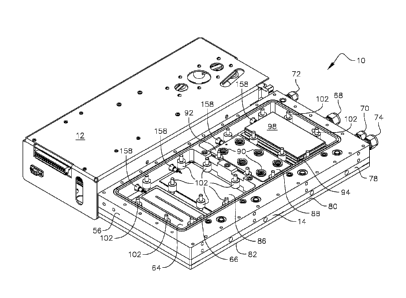
Referring to Fig. 3, a modular quad block, liquid
cooled, electro-mechanical ozone generating device 10 of the
present invention is shown. Device ln has an upper housing
12 and a lower housing 14, such that when standing upright in
a vertical position (see Fig. 13), upper housing 12 has a
slightly greater width than that of lower housing 14 and also
a slightly greater length. Upper housing 12 encloses all of
the electronic components needed to operate the ozone
generating device 10 (see Figs. 12 and 18-20), whereas lower
housing 14 encloses all of the meuhcthival uumpuuehtb ----- uf
device 10 that include one or more ozone generating cells
(see Figs. 4-11 and 21). As further shown in Fig. 3 (and
also in Figs. 12 and 18), upper housing 12 includes a series
of fans 16 positioned along a top end 18 of upper housing 12
(in the preferred embodiment there are three fans 16 employed
along top end 18, although other nothing herein limits the
use of just one or more than three fans 16). Fans 16 provide
air cooling to a set of transformers 20 (see Figs. 12 and 18)
that are used in the powering scheme of device 10, which will
be more fully discussed hereinafter.
Referring to Figs. 12-14, device 10 is shown in its
normal upright or vertically disposed position. Accordingly,
device 10 has a left side 22, a right side 24 and a bottom
CA 02774687 2012-03-16
WO 2011/035074 PCT/US2010/049195
CO1-003-0009 21
end 26. What is particularly meant by its "normal upright or
vertically disposed position" is the position or orientation
that the device 10 is most typically used when employed.
However, nothing herein limits that device 10 be used in any
other orientated positions of which are shown through out
many of the other figures herein for the purposes of
illustrating and describing each and every part of device 10.
However, as seen in Figs. 12-14, this vertical orientation
is used in the preferred embodiment.
Referring now to Fig. 13, it is shown that device 10 has
a serial interface connector 28 (such as a DB9 connecter) on
a front face 30 of upper housing 12 used to connect device 10
to a PLC (programmable logic control). Further, device 10
also has a standard analog interface connector 32 (such as a
RS232 or other interface) on upper housing front face 30 for
use in providing a computer interface protocol to the device
processor.
Referring now to Figs. 4-11 and Fig. 21, the internal
mechanical paLts that make up the ozone geneLating cells ale
shown in varying views and different perspectives and will
now be discussed in full detail. First, referring to Fig. 4,
device lower housing 14 includes a top cover 34 (see Fig. 3),
which can he made from aluminum, for example, a first section
layer 36 (detail shown in Fig. 10) which on a bottom side 38
(see Fig. 10) includes four separate liquid inlet channels
40, four indented liquid circulation areas 42 to cool the
ozone of four separate generation cells of device 10 and a
hot liquid outlet manifold 44, which is in fluid
communication with a liquid outlet port of device 10 to be
discussed hereinafter. A top side of first section layer 36
(not shown) is machined flat. A second section layer 48 has
a top side 46, as seen in Fig. 11, which has four separate
CA 02774687 2012-03-16
WO 2011/035074
PCT/US2010/049195
CO1-003-0009 22
milled indents 50 supporting a series of parallel disposed
fins 52, which define a continuous fluid channel 54. First
section layer bottom side 38 mates with second section layer
top side 46 to create a series of sealed internal liquid
coolant systems, one each for each ozone generation cell of
device 10, wherein all of the ozone produced is internally
cooled within device 10 before being porting there out.
Referring now to Fig. 9, second section layer 48 also
has a bottom side 63, which has two divided quadrants and has
an ozone micro-channel network plate 62 inserted there
within. Plate 62 has four separate ozone micro-channel
networks 64 (one each for each ozone generating cell),
wherein the plasma reaction occurs that results in the ozone
production, of which will be more fully described
hereinafter. On each of the ozone micro-channel networks 64,
there is an orifice 66 for creating a fixed pressure drop
within the respective ozone generating cell and for porting
the ozone that is created in each sub-cell of each ozone
generation cell to an ozone-out port. Suuud ---------------------- tion layer
48 is positioned juxtaposed to first section layer 36 such
that the liquid coolant system keeps the ozone relatively
cool during the plasma generation process. This unique
internal cooling process is a vast improvement over the prior
art and eliminates the need for internal piping or external
cooling devices and of which to date and has never been seen
before in the prior art. In the preferred embodiment, water
is used as the liquid coolant. However, nothing herein
limits the use of other like property liquids.
As seen in Figs. 8 and 21, a center body framing element
56, positioned within lower housing of device 10 (see Figs.
4-6), has an oxygen-in port 68, a water-in port 70, a water-
out port 72 and an ozone-out port 74. These four ports are
CA 02774687 2012-03-16
WO 2011/035074 PCT/US2010/049195
C01-003-00D9 23
formed along a left side wall 76 of center body framing
element 56, of which is at a rear portion of device 10 of the
present invention when it is vertically disposed and in use
(see Figs. 13 and 17). Center body framing element 56,
generally formed as a rectangular body, is further divided
into two quadrants 58 (see Fig. 8), which are separated by a
dividing bar 60. Quadrants 58 are largely hollowed-out but
house the forced distribution and equalization system (to be
discussed in further detail hereinafter), wherein most of the
oxygen accumulates during the ozone generation production
process.
Referring now to Fig. 5, device 10 is shown having top
cover 34 (see Fig. 3), and first and second section layers 36
and 48 (see Fig. 4), respectively, removed and third section
layer, center body framing element 56, clearly shown. This
figure illustrates that device 10 employs, in the preferred
embodiment, four ozone generating cells, two each in the two
quadrants 58 formed in center body framing element 56 by
dividing }Dal 60. It is important to remember that in the
preferred embodiment each ozone generating cell is really
made up of two "sub-cells" in that two plasma generating
pathways are employed for each cell as previously shown and
described in Fig. 2.
With reference to Figs. 5-7, it is shown that device 10
employs four forced distribution and equalization systems 84
(see Fig. 5) that generally locate within the center body
framing element two quadrants 58. With specific reference to
Figs. 6 and 7, the various structural components that make up
the pressure equalization systems 84 of the present invention
are shown therein. In particular, for each pressure
equalization system 84, there is a first (bottom) ceramic
plate 86 positioned on top of the "bottom" ozone micro-
CA 02774687 2012-03-16
WO 2011/035074 PCT/US2010/049195
CO1-003-0009 24
channel network 64 (see Fig. 7). Then a bottom plate 97 made
of stainless steel is placed on top of first ceramic plate
86. Thereafter, a first stainless steel plate 88 having a
plurality of springs 90 (see Fig.6) located about a top
surface 92 of plate 88 is placed on top of first (bottom)
ceramic plate 86. Thereafter, a second stainless steel plate
94 is positioned on top of the plurality of springs 90 so
that a small gap 96 is formed (see Fig. 7) for allowing a
specific amount of force (psi) for uniform force or pressure
distribution.
Thereafter, a top plate 98 made of stainless steel is
positioned on top of second stainless steel plate 94 for
providing the same purpose - they push against each other and
create the uniform distribution of force and adjust for any
inconsistencies that would normally occur.
Finally, a second (top) ceramic plate 100 (see Figs. 5
and 7) is positioned on top of top plate 98. It should be
noted again that when device 10 is orientated it is vertical
position of standard use (as shown in Figs. 12, 13 and 17),
then top to bottom can clearly be understood to mean left to
right.
With continuing reference to Figs. 5-7, it is shown that
a plurality of locators 102 are employed throughout lower
housing 14, which are used to secure and/or "locate" pressure
equalization systems 84. In the preferred embodiment,
locators 102 are made from polytetrafluoroethylene (PTFE),
also commonly known as TeflonTm. However, any fluoropolymer
or other like material having characteristics that have
excellent thermal and electrical insulation properties and a
low coefficient of friction can be employed herein. And
therefore, nothing limits the use of only TeflonT" for
locators 102.
CA 02774687 2012-03-16
WO 2011/035074 PCT/US2010/049195
C01-003-00D9 25
Although not shown directly in Figs. 5-7 because various
components such as the pressure equalization system 84 and at
least ozone micro-channel network 64 in Fig. 6 are covering
them, as well fourth and fifth section layers, 78 and 80
respectively in Fig. 7, but another ozone generating "sub-
cell" and another liquid coolant system are employed (as
previously described and shown in Figs. 9-11) on a bottom
side of each pressure equalization system 84 within center
body framing element 56. However, with reference to Fig. 7,
bottom (or left) ozone micro-channel network 64 can be seen
directly under first (bottom or left) ceramic plate 86. Then
with reference to Figs. 5 and 6, a fourth section layer 78 is
shown which is analogous to the second section layer 48 shown
in Fig. 9. Thereafter, a fifth section layer 80 is provided,
which is analogous to first section layer 36 shown in Fig. 10
except that the water inlets 40, water circulation areas 42
and the water outlet manifold 44 are all disposed on a bottom
side (not shown). Further, as to fourth section layer 78,
all of the indents 50, fins 52 and the continuous channel 54
formed around fins 52 are disposed on a bottom side (also not
shown) thereof to create the same novel internal liquid
coolant system of that previously described above and used in
lower housing 14 of device 10 of the present invention.
Finally, a bottom cover 82 is placed there over to completely
enclose lower housing 14 (see Fig. 5-7), save the four ports
previously described for water-in and out, 70 and 72, oxygen-
in 68 and ozone-out 74 all formed in center body framing
element 56. It should be noted that lower housing 14 has
been described to have a top and bottom side cover, 34 and
82, respectively. However, it is understood that when device
10 is orientated for use in a vertical position that bottom
cover 82 is on the left side of device 10 while top cover 34
26
is on the right side thereof. Further, the same can be said
about the various section layers of lower housing 14 in that
the fifth and fourth sections layers, 80 and 78 are on the
left side and the first and second section layers, 36 and 46,
are on the right side of device 10 when orientated in a
vertical position or used in relation to center body framing
element 56. It should also be noted that a great amount of
machining has been done on all of the flat surfaces of the
section layers as previously described, in order to reduce
the number of parts and make the lower housing work more
efficiently, which is a vast improvement over the prior art.
It is further noted that such novel approach has never been
seen before in the prior art, especially as it applies to the
great amount of internal manifolding that is present within
lower housing 14.
Referring now to Figs. 13 and 14, it is shown how device
10 is typically orientated in a vertical position for use. A
tray 104 is employed, which when filled or at least contains
two or more modular devices 10 of the present invention, a
rack (resembling a shelf, not shown) is formed.
Referring to Fig. 13, it is shown that tray 104 contains a
series of slots 114 formed in a bottom surface 116 of tray
104 that are separated by a plurality of vertically disposed,
frontal oriented partitions 118. These partitions serve as
part of the stabilization system and provide rotational
support to the module devices 10 when placed in slots in tray
104. It should be noted though that the preferred tray 104
(shown in Fig. 22 and 23) has ten slots 114 for ten modular
devices 10 and only five partitions 118 such that a first
slot 114 is formed on a far left side separated by a first
partition 118 and then two more slots 114 followed by a
second partition 118 followed by two more slots 114 and then
CA 2774687 2020-02-05
CA 02774687 2012-03-16
WO 2011/035074 PCT/US2010/049195
CO1-003-0009 27
a third partition 118 followed by two more slots 114 and then
a fourth partition 188 followed by two more slots 114 and
then a fifth and final partition 118 followed by a final far
right slot 114. Notwithstanding, nothing herein limits the
present invention from employing a variety of different
configurations for the slots and partitions, and certainly
nothing herein limits the invention to just ten modular
device per rack.
With reference now to Figs. 13 and 16, it is shown that
tray 104 has a back wall 120 perpendicularly disposed to
bottom surface 116. Tray 104 is fabricated in the preferred
embodiment from a single solid block of aluminum, although
other metals can be employed and as well fastened components
can be used to form tray 104. Positioned in vertical
alignment along back wall 120 are a series of module
connection rails 122, which are centered in each slot 114
(see Fig. 16). There are four connectors on each rail 122,
one each (from top to bottom) for water-out 124, oxygen-in
126, wateL-in 128 and ozone-out 130. The positioning of
these four connectors are not limited to this configuration
but are disposed so accordingly, in this preferred embodiment
to align with the reciprocal four connectors of device 10
when inserted within each slot 114 (see Fig 17). It is noted
that connectors 124, 126, 128 and 130 all "float" (i.e., they
each have a small amount of play or movement) to allow for
easy connection and module alignment of each device 10 in
each slot 114 of tray 104. Further, there is a plurality of
protuberances 180 vertically aligned within each module
connection bar 120 that provide horizontal stabilization
(i.e., side to side) for device 10 when inserted into a slot
144 of the tray 104. Although not shown in Fig. 13, a series
of tubing is connected to each tray 104 that combines each of
CA 02774687 2012-03-16
WO 2011/035074 PCT/US2010/049195
CO1-003-0009 28
the four individual connectors to a single input or output,
which can be seen on a left side 132 of tray 104 at (from top
to bottom) water-out 134, oxygen-in 136, water-in 138 and
ozone-out 140. There is also an identical set of connectors
on the right side of tray 104 (not shown), which can be
either plugged closed or left open to "daisy chain" a series
of racks. Nothing herein requires the use of one side or the
other (left or right) specifically if only one side is to be
used or for that matter a hybrid of use of the openings
wherein some of the openings on one side are used, while
others are used on the opposed side.
With reference now to Figs. 15 and 16, it is shown that
tray 104 has a top end 142 that supports an electrical
connection block 144 for each slot 114 to connect each device
10 inserted within tray 104 to a common power source and
ground and is responsible for delivery of the high power
electricity to the modular devices 10 that is needed to run
said device. Electrical connection block 144 can provide
either be a hot, neutral and ground uuuuution, a 3 phase
connection or a DC bus. Each electrical connection block 144
is essentially axially aligned with a respective module
connection bar located along the back side 120 of tray 104.
Further, a pair of locator pins 146 is disposed at tray top
end 142 directly below and surrounding electrical connection
block 144 for aligning and securing each modular device 10 to
tray 104 in each respective slot 114 when engaging module
connection rails 122. Locator pins 146 extend outwardly from
tray back wall 120 and are in parallel with tray bottom
surface 116. Locator pins 146 and electrical connection
block 144 are part of the same floating block that assists in
aligning and securing each modular device 10 to tray 104 in
each respective slot 114. Although a pair of locator pins
29
146 is used in the preferred embodiment, nothing herein
limits the use of just one or more than two locator pins 146.
Referring to Fig. 17, a rear perspective view of device
10 is shown wherein a series of couplers 172, 174, 176 and
178 are connected to the water-out port 72, oxygen-in port
68, water-in port 70 and ozone-out port 74, respectively, of
center body frame 58 (see Fig. 21). These four couplers,
172, 174, 176 and 178, are used in alternate embodiments
wherein tray 104 is not used and instead either a Separate
manifold (not shown) is provided to interconnect two or more
modules 10 or wherein a single module 10 is used and tubing
(not shown) is directly connected to couplers 172, 174, 176
and 178.
Referring now to Fig. 18, all of the electrical drive
and power components needed to operate each device 10 are
housed within top housing 12. Besides the transformer set-up
20, as previously described, there is a small power supply
148 that produces a lower voltage DC to run a circuit board
and an internally disposed fan 150 that blows air onto a heat
sink 152 positioned juxtaposed to the high energy producing
electrical power components 154 that acts as through-puts
from transformers 20 to the ozone generation cells.
Referring now to Figs. 19 and 20, the high voltage
output wires 156 that come from each transformer 20 connect
to individual ceramic feed-through components 158 that handle
a voltage throughput in the range' of 3500-4000 volts, which
then delivers the high energy needed to create the plasma
and eventual ozone production within each ozone generating
cell. Each ceramic feed-through component 158 represents the
e
center of each of the ozone generating cells. Since the
spacing is so small between each feed-though, the -1 use
of the previously mentioned
CA 2774687 2020-02-05
30
, =
Francis transformer set-up of US Patent No.
7,746,001 is preferred.
Referring now to Figs. 24-28, an alternate embodiment
device 160 of the present invention is disclosed that
utilizes an air-cooled system in place of the liquid-cooled
system as previously described. As such, there are no water-
in or water-out ports, but instead just oxygen in 68 and
ozone out 74 as seen in Fig. 28. Further, the tray (not
shown) used with alternate air cooled device 160 does not
employ any of the other liquid cooled parts such as water-in
128 and water-out 124 in module connection bar 122 nor water-
in 136 and water-out 140 located on the left tray side:I32.
However all of the oxygen supply and ozone-out ports remain.
Further, as to alternate device 160, the water inlets
40, the water circulation areas 42 and the water manifold 44
are also not employed within the module. Instead, as shown
in Figs. 24-28, an air-cooled system including a plurality of
large capacity fans 162 are employed on both sides of the
module. As shown in Fig. 26, a fan ,mounting frame 164 is
employed underneath fans 162 to locate them directly above a
pair of large capacity heat sinks, of which-both are more
clearly seen in Fig. 27. -Both the fan mounting frame 164 and
the pair of large capacity heat sinks 166 are employed on
both sides of the moduie
As can also be appreciated by referring to Figs. 24-28,
the five layer system of the preferred embodiment device 10
is not employed with alternate device 160, but instead merely
a three layer system. What remains common is that both
embodiments employ center body frame 56. And as seen in Fig.
28, center body frame 56 houses the ozone generation cells
much to the same configuration as seen in the preferred
device 10 of Figs. 5 and 6, absent any liquid coolant
CA 2774687 2020-02-05
CA 02774687 2012-03-16
WO 2011/035074 PCT/US2010/049195
CO1-003-0009 31
components. The remaining components are employed in the
air-cooled alternate embodiment as shown in Figs. 24-28. For
avoidance of doubt, the three layer configuration of
alternate device 160 is clearly seen in Figs. 24-27 and the
section layers that surround center body frame 56 are end
potions 168 and 170 of the upper and lower heat sinks 166.
It should also be noted that alternate embodiment 160 has
been described to have upper and lower heat sink portions,
168 and 170 respectively. However, it is understood that
when alternate device 160 is orientated for use in a vertical
position that lower heat sink end portion 170 is on a left
side of device 160 while upper heat sink end portion 168 is
on the right side thereof.
Equivalent elements can be substituted for the ones set
forth herein to achieve the same results in the same way and
in the same manner.