Note: Descriptions are shown in the official language in which they were submitted.
CA 02774752 2012-03-20
WO 2011/050905
PCT/EP2010/006231
1
DESCRIPTION
CATCHING DEVICE FOR AMMUNITION SHELLS AND/OR CONNECTORS
The present invention relates to a catching and collecting device for
ammunition shells and to
the associated connector elements of the catching device in weapon stations,
in particular
weapon stations that have a mounted weapon.
Military vehicles are used increasingly with weapon stations for self-defense
and for engaging
enemy targets. The weapon stations enable the operator to observe and engage
target objects
under armored protection. Generally, such weapon stations are mechanical /
electrical or
remote control in design. Remote controlled weapon stations are also referred
to as Remote
Weapon Station (RWS) or Remote Controlled Weapon Station (RCWS).
Weapon stations are increasingly armed with military weapons, such weapons
having generally
been being designed for manual use and as such are handled and operated
directly by soldiers.
To adapt these weapons to, or mount them on the weapon stations, the former
are expanded
using special adapters and fittings and thus rendered remote controllable.
Such weapons, for
example, machine guns (MG) or grenade launchers (GMK or AGL) have specialized
ammunition
feeds and shell / connectors (belt link) ¨ ejection ports. Generally, weapon
stations are
equipped with ammunition containers which accommodate the ammunition belts
with the
ammunition and, where desired, frequently have collector receptacles for
receiving the empty
shells / connectors.
CA 2 200 922 C proposes a collector receptacle for empty shells on the side of
a portable fire
arm. DE 102 37 688 B4 describes a shell and belt link collector device
provided preferably for a
machine gun mounted on a gun carriage, wherein a cartridge case channel is
screwed to the
CA 02774752 2012-03-20
WO 2011/050905
PCT/EP2010/006231
2
gun carriage and the belt link channel is moveable about a pivot. A bag for
cartridge cases is
mounted on the cartridge case channel which receives both the cartridges and
the belt links.
However, for mountable weapons it is difficult, if not impossible to connect
such devices to a
weapon station, in order to prevent empty shells, etc. from lying strewn about
on the vehicle
deck and, for example, blocking the vehicle hatches or from being strewn about
the shooting
periphery.
Weapon stations that have large stores of ammunition and weapons with a high
elevation
range (weapon ¨ elevation) use open collector receptacles to avoid obstruction
of the weapon
due to jammed shells. Such collector devices are frequently arranged
underneath the weapon
ejection port. The collector devices arranged beneath the weapon station
receive the majority
of shells when the ammunition is ejected downwardly.
CH 526 086 A discloses a gun mount for an automatic firearm which has an
ejection port for
empty cartridge shells at the rear which are diverted by a guide plate into a
receptacle. To
ensure that the shells reach the container regardless of the elevation of the
weapon, a second
guide plate is attached, whereby the first guide plate is pivotally attached
in the area at the rear
edge and the second guide plate is attached in the area of the front edge of
the ejection port,
on the elevatable portion thereof, and both are guided as a single fixed part
as the weapon is
elevated.
From DE 102 07 233 Al it is known to connect a shell catch holder at the rear
of large caliber
weapons, which holder, once the shot has been fired and the breach opened,
receives the
empty shells of the respective ammunition ejected from the rear out of the
weapon barrel.
CA 02774752 2016-09-01
31067-12
3
The object of the present invention is to show a catching device, which
ideally also
catches laterally ejected parts, such as shells and / or connector elements /
belt links,
even in the case of an elevatable weapon, and guides them into a receptacle.
The present invention is based on the concept of attaching a catching device
and a
collecting receptacle cooperating therewith, for example, laterally to a
weapon station.
In this arrangement, the collecting receptacle may, in a particular
embodiment, form
part of the catching device. In the preferred embodiment the collecting
receptacle is
arranged separately and either adjacent to or behind the weapon station.
Alternatively,
it is feasible to attach the collecting receptacle around the entire
circumference of the
weapon station. After firing, the empty shells and/or the belt links /
connector elements
are guided toward the lateral catching device and from there into the
collecting
receptacle. Due to the special design of the catching device, the guidance is
preferably
done by sliding the parts along the rear wall of the device.
The proposed concept may also be used in weapon systems in which, after the
ammunition is fired, the belt links must still be separated from one another
since they
do not separate by themselves and the belt links remain connected by hooks and
loops. In such case it is possible to attach a belt link separation device in
front of the
catching device. A separating device of this type is described in EP 1 985 960
Al.
Another separating device is also shown in the not previously published
DE 10 2009 031 286.2 of the applicant. The separating device includes both a
lower
and upper guide, wherein the lower guide is aligned to the width of the
connecting site,
that is, to the width of the hooks and loops, and is formed by two tongue-like
runners or
the like. The upper guide is comprised preferably of a spring into which a
control cam is
connected for guiding the belt link being separated. The width of the spring
is
preferably identical to the width of the hooks and loops. In a preferred
embodiment, the
former is attached behind the ejection device also shown in the not previously
published DE 10 2009 031 285.4 of the applicant, which ejection device in turn
casts
the separate belt links into a catching device not further specified herein.
CA 02774752 2016-09-01
31067-12
4
Attachment to the weapon station is accomplished preferably by so-called quick
release fasteners, etc. thus making it possible to simply and quickly mount or
remove
in particular the catching device. It is understood that the collecting
receptacle as well
can be attached to the weapon station by means of quick release fasteners. In
this
- way, it is possible to remove the catching device and the receptacle from,
or attach it
to, the weapon station using these quick connecting means ¨ depending on
client
demand or particular use. Selecting lighter materials minimizes additional of
weight
while providing optimal performance. An additional advantage of this design is
that it
can be adapted to the respective type of weapon, caliber and type of ejector
since it
is not limited to being attached from the side.
In some embodiments of the present invention, there is provided a catching
device
for shells and / connector elements on a mountable and elevatable weapon
station,
comprising a substantially U-shaped frame having two side sections and an
intermediate section as a rear wall of the catching device, by means of which
the
shells / connector elements are guided into a collecting device, wherein the
catching
device is attached to a lateral ejection port of the weapon station and to a
rear
ejection port of the weapon station, the collecting device can be attached at
the rear
end, on the side or about the entire circumference of the weapon station, and
the
catching device and the collecting device are adapted to the weapon station by
means of quick release fasteners.
The present invention will be described in greater detail below with reference
to an
exemplary embodiment and the drawings. In the drawings:
Fig. 1 is a rear view of an elevatable weapon station,
Fig. 2 is the ammunition flow in the weapon station shown in Fig. 1.
Fig. 1 shows a weapon station 1 equipped with an ammunition container 2
indicated
for stocking ammunition (not shown in detail) for a weapon, for example, a
mounted
machine gun. The weapon 4 is arranged on or supported in the weapon station 1
and
CA 02774752 2016-09-01
31067-12
4a
is capable of being elevated to compensate ballistically for the firing
distance. It is
understood that the weapon 4 is also adjustable with respect to the azimuth.
When
elevated, the relative position of the weapon 4 is known to change, however,
as is the
entry and exit of the ammunition of the weapon station 1.
CA 02774752 2012-03-20
- W02011/050905
PCT/EP2010/006231
For this reason, catching device (-means) 5 is added to the weapon station 1,
being fixed to the
weapon station 1 by means of fasteners 6. The catching device 5 diverts the
ejected parts into
a preferably separate collecting receptacle 3. The fasteners are preferably in
the form of quick
release fasteners.
The catching device 5 is comprised of a substantially U-shaped frame 5.1 with
two side sections
5.2 and an intermediate section 5.3, preferably half-rounded in design. This
intermediate
section 5.3 constitutes a rear wall for the catching device. To save weight,
provision is made in
a preferred embodiment for a type of covering for the intermediate section 5.3
disposed
between the two outer sections 5.2 of the frame 5.1, such that the rear wall
is defined by the
covering. For coverings it is possible to use durable fabric, leather, fibers,
etc.
The catching device 5 is of a plastic and/or metal construction, preferably in
the form of a
frame, wherein a covering of the side sections 5.2 using durable fabric,
leather, fibers, etc. is
also contemplated. However, sections 5.1 to 5.3 constructed completely of
plastic and/or
metal are also conceivable.
A lateral covering of plastic or metal construction can be omitted, however,
if the half-rounded
intermediate section 5.3 is small in shape (smaller radius), thereby making it
impossible for the
parts being collected to slide out between the side sections 5.2.
A collecting receptacle 3 is preferably attached to the rear end of the weapon
station 1 and
thereby connected to said station, such that the collecting receptacle 3 can
be carried along in
azimuth when the weapon station 1 is rotated. Though structurally more
complex, it is possible
to attach the receptacle so that it surrounds the weapon station 1 on all
sides, and is designed
as a fixed part of a vehicle roof or an object (not further shown), on which
the weapon station 1
is mounted.
CA 02774752 2012-03-20
W02011/050905
PCT/EP2010/006231
6
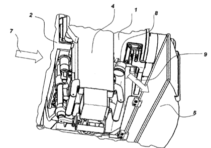
Fig. 2 shows by way of arrow 7 the flow of ammunition not further detailed
herein. The
weapon 4 draws the ammunition in a manner known in the art, fires the
projectile (not shown
in detail) and conveys the shell / connector 8 in the direction 9 out of the
weapon 4. The
catching device 5 catches the former and conveys it, preferably by guiding it
off or downwardly,
into the collecting receptacle 3.