Language selection

Search

Patent 2775108 Summary

Third-party information liability

Some of the information on this Web page has been provided by external sources. The Government of Canada is not responsible for the accuracy, reliability or currency of the information supplied by external sources. Users wishing to rely upon this information should consult directly with the source of the information. Content provided by external sources is not subject to official languages, privacy and accessibility requirements.

Claims and Abstract availability

Any discrepancies in the text and image of the Claims and Abstract are due to differing posting times. Text of the Claims and Abstract are posted:

  • At the time the application is open to public inspection;
  • At the time of issue of the patent (grant).
(12) Patent: (11) CA 2775108
(54) English Title: KNEE-JOINT BANDAGE MADE OF ELASTIC MATERIAL AND HAVING AN APPLICATION AID
(54) French Title: BANDAGE DE ROTULE FAIT D'UN MATERIAU ELASTIQUE ET COMPORTANT UN DISPOSITIF D'AIDE A L'INSTALLATION
Status: Granted
Bibliographic Data
(51) International Patent Classification (IPC):
  • A61F 5/01 (2006.01)
(72) Inventors :
  • REINHARDT, HOLGER (Germany)
  • BERENDT, UWE (Germany)
(73) Owners :
  • BAUERFEIND AG (Germany)
(71) Applicants :
  • BAUERFEIND AG (Germany)
(74) Agent: VASS, WILLIAM B.
(74) Associate agent:
(45) Issued: 2016-08-30
(86) PCT Filing Date: 2010-09-21
(87) Open to Public Inspection: 2011-03-31
Examination requested: 2013-12-10
Availability of licence: N/A
(25) Language of filing: English

Patent Cooperation Treaty (PCT): Yes
(86) PCT Filing Number: PCT/EP2010/005773
(87) International Publication Number: WO2011/035885
(85) National Entry: 2012-03-23

(30) Application Priority Data:
Application No. Country/Territory Date
20 2009 012 967.5 Germany 2009-09-25

Abstracts

English Abstract


The invention relates to a knee-joint bandage made of elastic material and
having a pad configured for
the knee cap, which bandage is provided, on at least one side of the pad, with
a flexible stabilizing rod
that extends along the length of the bandage. The stabilizing rod is provided
with a grip part and is
embedded in a pocket which is arranged on the bandage and which is firmly
connected to the material
of the bandage at edge zones and at the end of said bandage arranged above the
knee cap.


French Abstract

L'invention concerne une genouillère (1) qui est constituée de matériau élastique et pourvue d'un rembourrage associé à la rotule et qui est équipée au moins sur un côté du rembourrage d'une barre de stabilisation (8, 9) flexible s'étendant sur la longueur de la genouillère. Selon l'invention, la barre de stabilisation (8, 9) est pourvue d'un dispositif de préhension et est intégrée dans une poche qui est disposée sur la genouillère (1) et est reliée à demeure par ses zones de bord (10, 11) et à son extrémité disposée au dessus de la rotule au matériau de la genouillère (1).

Claims

Note: Claims are shown in the official language in which they were submitted.

- 4 -

CLAIMS
1. A knee-joint bandage constructed of an elastic material and having a pad
configured
for a knee cap, the knee-joint bandage comprising:
on at least one side of the pad, a flexible stabilizing rod, wherein the
stabilizing
rod is embedded in a pocket arranged on the bandage, the pocket being firmly
connected to the material of the bandage at edge zones and at the end of the
bandage above the knee cap; and
wherein the stabilizing rod comprises a grip section containing as an eyelet
with a
hole defined therein, and wherein the stabilizing rod and the grip section are

embedded in the pocket.
2. The knee-joint bandage according to claim 1, wherein the stabilizing rod
is
substantially continuously welded to the material of the bandage.
3. The knee-joint bandage according to claim 1, wherein the grip section
comprises a
thicker portion.
4. The knee-joint bandage according to claim 1, wherein the stabilizing rod
is
substantially continuously welded to the material of the bandage, and the grip

section comprises a thicker portion.
5. The knee-joint bandage according to claim 1, wherein the grip section is
located at
the end of the stabilizing rod opposite a lower edge of the bandage and
comprises a
thicker portion at a side remote from the stabilizing rod.

Description

Note: Descriptions are shown in the official language in which they were submitted.


CA 02775108 2015-04-15
=
Knee-joint Bandage Made of Elastic Material and Having An Application Aid
The invention relates to a knee-joint bandage made of elastic material and
having a pad for the knee
cap, which bandage is provided on at least one side of the pad, with a
flexible stabilizing rod that
extends along the length of the bandage.
Such a bandage is shown and described in DE 36 37 879 Al. This bandage is
provided with spring strip
rods which extend practically across the whole length of the bandage and
particularly support the knee-
joint during bending thereof.
Such knee-joint bandages more or less tightly span the knee-joint depending on
the elasticity of the
bandage material which results in that application of the bandage and slipping
it up across the heel and
the knee-joint, is made difficult and requires a substantial force effort in
any case. For facilitating the
application of such a knee-joint bandage, one has already been proposed
according to WO 00/49982 to
provide one or several loops at the upper edge of the knee-joint bandage in
order to grip these loops
with a finger and then to pull them up whereby the bandage stitched to the
loops is pulled along and can
be slipped across the knee. For this purpose, a very solid connection between
the loop and the material
of the knee-joint bandage is required so that the loop cannot break away upon
pulling up the bandage.
It is an object of the invention to facilitate the application of such a knee-
joint bandage with the required
security for the bandage material. According to the invention, this is done
whereby the eyelet comprises
a thickened section or portion at its side remote from the stabilizing rod.
Herein, the stabilizing rod
comprises a double action, i.e., at the one hand, for stabilizing the knee-
joint and, on the other hand, as
application aid for which purpose the stabilizing rod is provided with a grip
part which can easily be
gripped and directly passes on to the bandage material a pulling force applied
to it. Embedding the
stabilizing rod into the pocket arranged at the bandage, lends a sufficiently
strong connection of the
stabilizing rod to the material of the bandage so that a pulling force exerted
to the grip part, may be

CA 02775108 2015-04-15
=
. - 2 -
distributed over the bandage material, and, therefore, it is not subject to a
particularly high additional
stress upon application.
The stabilizing rod provides a double or dual function, i.e., on the one hand,
for stabilizing the knee-joint
and, on the other hand, as an application aid for which purpose the
stabilizing rod is provided with a grip
part which may easily be gripped and transfers a pulling force applied to it,
directly to the bandage
material.
Upon exerting a pulling force to the grip part, it is applied to the complete
length of the bandage in this
way.
The grip part is conveniently formed as an eyelet wherein the passage through
a hole is located
approximately at right angles to the bandage material. In case of such an
arrangement of the grip part, it
can be gripped directly with one finger which passes through the eyelet and
transfers the pulling force
conveniently to the bandage in this way. The gripping function of the eyelet
may be further facilitated by
providing a thickened or thicker portion or section on the side remote from
the stabilizing rod.
An embodiment of the invention is shown in the figure.
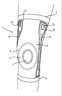
Fig. 1 shows a plan view of a knee-joint bandage according to an embodiment of
the present invention
and applied to a knee;
Fig. 2 shows a grip section or part of the knee-joint bandage of Fig. 1; and
Fig. 3 shows a side view of the grip section of Fig. 2.
The knee-joint bandage 1, shown in Fig. 1, comprises a stocking 2, formed or
constructed of elastic
textile material, and the two edges 3 and 4 at its two ends which contribute
to the slipping safety of the
bandage 1. Furthermore, the edges 3 and 4 are formed out of a material which
comprises a lower
tension as compared to the stocking 2 in order to only slightly constrict the
leg of the user at the
respective positions. At the front side of the knee-joint bandage 1, a
profiled insert with a pad 5 is
inserted into the stocking 2 which inserts consists, for example, out of foam
material or silicon and has a
substantial elasticity. The pad 5 is covered on the inner side of the stocking
2, by a cover which is
connected, for example, by gluing, at its edges 6 to the stocking 2. The pad 5
leaves free, at its central

CA 02775108 2015-04-15
- 3 -
portion, an area into which the knee cap 7 approximately fits. The knee cap 7
is, thereby, embraced by
the pad 5. In so far, a knee-joint bandage arranged in a manner known per se
is concerned.
Next to the pad 5, the bandage 1 is provided with two stabilizing rods 8 and 9
which extend substantially
across the complete length of the bandage 1 and which provide for the bandage
1 applied to the leg, not
being able to contract in its length direction. Each of the two stabilizing
rods 8 and 9 is taken up in a
pocket which is glued to the bandage 1 by means of the bordering zones 10 and
11, respectively, to the
material of the bandage 1. Depending on the desired degree of stabilization,
the bandage 1 may also be
provided with one stabilizing rod only.
Reference is next made to Figs. 2 and 3, which show a more specific
arrangement of the stabilizing rods
8, 9 in the area of its grip part, according to an embodiment of the
invention.
Each of the two stabilizing rods 8 and 9 comprises, at an upper end, a grip
part or section 14 containing
an eyelet 12 and 13, respectively, which grip part allows gripping the bandage
1 at its application and
pulling up thereof along the leg with the finger and, thereby, facilitates the
application of the bandage
since the bandage 1 as a whole is pulled along on application of a
corresponding pulling force to the
grip part 14 and the stabilizing rod 8, 9, whereby it is possible without
further means to draw the
bandage 1 smoothly across the foot, the calf and the knee into its final
position.
The stabilizing rods 8 and 9 contained in the pockets, are, thereby, tightly
received by the respective
pockets thereby that their edge zones 10 and 11 are formed each as a narrow
circumferential strip
which is directly connected to the material of the bandage, for example by
welding or by gluing.
Fig. 2 shows a stabilizing rod 9 alone with the grip part or section 14 which
comprises the eyelet or hole
12. The grip part 14 comprises an elastic plastic material, in its lower end,
the stabilizing rod 9 is
inserted and is tightly gripped by the material of the grip part 14. The
stabilizing rod 9 comprises flat-
pressed turns of a helical spring so that a substantial elasticity or bending
is possible while being
secured against axial stretching, whereby the stabilizing rod 9 as applied to
the bandage 1 can also
bend.
Fig. 3 shows the grip part 14 with inserted stabilizing rod 9 in a side
elevation. As shown, the upper end
of the grip part 14, comprises the thickened or thicker section or portion 15
which serves to give a good
grip to a finger pushed into the opening 12 of the grip part 14 upon
application of the bandage 1.

Representative Drawing
A single figure which represents the drawing illustrating the invention.
Administrative Status

For a clearer understanding of the status of the application/patent presented on this page, the site Disclaimer , as well as the definitions for Patent , Administrative Status , Maintenance Fee  and Payment History  should be consulted.

Administrative Status

Title Date
Forecasted Issue Date 2016-08-30
(86) PCT Filing Date 2010-09-21
(87) PCT Publication Date 2011-03-31
(85) National Entry 2012-03-23
Examination Requested 2013-12-10
(45) Issued 2016-08-30

Abandonment History

There is no abandonment history.

Maintenance Fee

Last Payment of $263.14 was received on 2023-09-08


 Upcoming maintenance fee amounts

Description Date Amount
Next Payment if standard fee 2024-09-23 $347.00
Next Payment if small entity fee 2024-09-23 $125.00

Note : If the full payment has not been received on or before the date indicated, a further fee may be required which may be one of the following

  • the reinstatement fee;
  • the late payment fee; or
  • additional fee to reverse deemed expiry.

Patent fees are adjusted on the 1st of January every year. The amounts above are the current amounts if received by December 31 of the current year.
Please refer to the CIPO Patent Fees web page to see all current fee amounts.

Payment History

Fee Type Anniversary Year Due Date Amount Paid Paid Date
Application Fee $400.00 2012-03-23
Maintenance Fee - Application - New Act 2 2012-09-21 $100.00 2012-08-28
Maintenance Fee - Application - New Act 3 2013-09-23 $100.00 2013-09-16
Request for Examination $800.00 2013-12-10
Maintenance Fee - Application - New Act 4 2014-09-22 $100.00 2014-09-04
Maintenance Fee - Application - New Act 5 2015-09-21 $200.00 2015-08-31
Final Fee $300.00 2016-07-05
Maintenance Fee - Patent - New Act 6 2016-09-21 $200.00 2016-09-08
Maintenance Fee - Patent - New Act 7 2017-09-21 $200.00 2017-09-13
Maintenance Fee - Patent - New Act 8 2018-09-21 $200.00 2018-09-11
Maintenance Fee - Patent - New Act 9 2019-09-23 $200.00 2019-09-09
Maintenance Fee - Patent - New Act 10 2020-09-21 $250.00 2020-09-10
Maintenance Fee - Patent - New Act 11 2021-09-21 $255.00 2021-09-13
Maintenance Fee - Patent - New Act 12 2022-09-21 $254.49 2022-09-12
Maintenance Fee - Patent - New Act 13 2023-09-21 $263.14 2023-09-08
Owners on Record

Note: Records showing the ownership history in alphabetical order.

Current Owners on Record
BAUERFEIND AG
Past Owners on Record
None
Past Owners that do not appear in the "Owners on Record" listing will appear in other documentation within the application.
Documents

To view selected files, please enter reCAPTCHA code :


To view images, click a link in the Document Description column. To download the documents, select one or more checkboxes in the first column and then click the "Download Selected in PDF format (Zip Archive)" or the "Download Selected as Single PDF" button.

List of published and non-published patent-specific documents on the CPD .

If you have any difficulty accessing content, you can call the Client Service Centre at 1-866-997-1936 or send them an e-mail at CIPO Client Service Centre.


Document
Description 
Date
(yyyy-mm-dd) 
Number of pages   Size of Image (KB) 
Abstract 2012-03-23 1 13
Claims 2012-03-23 1 22
Drawings 2012-03-23 2 24
Description 2012-03-23 3 140
Representative Drawing 2012-03-23 1 13
Cover Page 2012-08-21 2 39
Abstract 2015-04-15 1 12
Claims 2015-04-15 1 28
Description 2015-04-15 3 144
Claims 2015-11-04 1 28
Representative Drawing 2016-07-25 1 7
Cover Page 2016-07-25 1 37
Change of Agent 2017-09-11 4 106
Office Letter 2017-09-22 1 24
Office Letter 2017-09-22 1 26
PCT 2012-03-23 10 323
Assignment 2012-03-23 5 130
Fees 2012-08-28 1 163
Prosecution-Amendment 2015-04-15 8 273
Prosecution-Amendment 2014-12-04 4 246
Fees 2013-09-16 1 33
Prosecution-Amendment 2013-12-10 1 34
Prosecution-Amendment 2014-06-20 1 30
Fees 2014-09-04 1 33
Examiner Requisition 2015-08-04 3 201
Fees 2015-08-31 1 33
Amendment 2015-11-04 3 93
Correspondence 2016-03-07 2 41
Final Fee 2016-07-05 1 46