Note: Descriptions are shown in the official language in which they were submitted.
CA 02775194 2012-04-20
GRILLING RACK /
FIELD OF THE INVENTION
The present invention relates to food grilling racks that can be used to
contain food and
then be placed upon a cooking surface such as an outdoor grilling surface. The
present invention
also relates to a method and apparatus for stuffing a selected food stuffing
into a food item such
as a pepper or other vegetable food item. More particularly, the present
invention relates to an
apparatus that holds a volume of food stuffing material (e.g., a rice based
stuffing, cheese based
stuffing or a mixture of meat and cheese and possibly other food items).
BACKGROUND OF THE INVENTION
Food items are often placed upon a perforated plate, which is then placed upon
a
barbecue pit, outdoor grill or other outdoor cooking surface. Such perforated
plates are
commercially available. At times, they are provided with handles for enabling
a user to lift and
move the plate before and after use. It is common and known to grill a number
of different food
items on such perforated grilling plates, such as onions, peppers, corn, and
other food items.
Some food items such as jalapeno peppers or bell peppers can be stuffed with
food items
such as a breaded mixture of rice and meat or seafood. In such a case, users
often cut the pepper
transversely or longitudinally and fill each of the cut halves with a selected
stuffing or filling.
One of the problems with the prior art grilling racks is that the food items
can often fall in
between the openings or become stuck in the openings.
SUMMARY
In accordance with an aspect of the present disclosure there is provided a
food grilling
rack for grilling elongated food items, comprising: a frame defined by a
plurality of connected
side walls; the frame including a lower corrugated sheet that provides
multiple troughs, each
trough having a lowest portion, said lower sheet attached to at least some of
said side walls; an
upper sheet of material that is supported above the sheet of corrugated
material; a plurality of
openings in the upper sheet of material, each opening being vertically aligned
with a lowest
portion of a trough; and there being a plurality of openings that are spaced
apart and aligned
vertically above a trough.
-1-
CA 02775194 2012-04-20
In accordance with another aspect of the present disclosure there is provided
a food
grilling rack for grilling elongated food items, comprising: a pan having a
plurality of connected
side walls and a pan bottom; the pan bottom wall being a lower corrugated
sheet that provides
multiple pan troughs, each pan trough having a lowest portion, said lower
corrugated sheet
attached to at least some of said side walls; an upper sheet of material that
is supported by the
pan above the sheet of corrugated material; and a plurality of openings in the
upper sheet of
material, each opening being generally vertically aligned with a lowest
portion of a said pan
trough so that an elongated food item placed in an opening rests in the lowest
part of the trough
and is laterally supported by the upper sheet at a said opening.
In accordance with yet another aspect of the present disclosure there is
provided a pepper
stuffing apparatus comprising: a receptacle having an interior, an upper end
portion with a larger
opening and a lower end portion with a smaller opening, a tapering portion in
between the upper
and lower end portions and a handle that enables a user to hold and manipulate
the receptacle; a
plunger having a head, a lower end portion with a shaft having a lower pushing
surface and a
joint that joins the head to the shaft; wherein the pushing surface has a
larger diameter portion,
the shaft tapering above the pushing surface to a smaller diameter portion
that is positioned
above the pushing surface and in the upper one half of the plunger; and the
smaller opening
having a diameter of less than one inch.
In accordance with still yet another aspect of the present disclosure there is
provided a
method of stuffing one or more hollow peppers having generally void interiors,
comprising the
steps of: cutting each of the pepper transversely to provide on each pepper, a
pepper opening;
providing a receptacle having an interior, an upper end portion with a larger
receptacle opening
and a lower end portion with a smaller receptacle opening, and a tapered
portion in between the
upper and lower end portions; filling at least part of the interior with a
food stuffing; aligning the
smaller opening with the pepper opening; manually moving a plunger into the
larger opening in
order to contact the food stuffing, the plunger having a shaft with an upper
end portion with a
handle configured to be gripped manually by a user and a lower end portion
having a food
pushing surface; pushing the plunger from the larger opening to the smaller
opening, wherein the
pushing surface pushes some of the food stuffing into the pepper via the
aligned smaller
receptacle and pepper openings; and wherein the receptacle tapered portion
directs the plunger
food pushing surface toward the smaller receptacle opening when a user moves
the plunger
-2-
CA 02775194 2012-04-20
within the interior and in a direction generally from the larger receptacle
opening to the smaller
receptacle opening.
In accordance with still yet another aspect of the present disclosure there is
provided a
method of stuffing one or more hollow peppers, each said pepper having a
hollowed interior,
comprising the steps of. cutting each of the pepper transversely to provide on
each pepper, a
pepper opening that is in communication with the hollowed interior; providing
a receptacle
having a receptacle interior, an upper end portion with a larger receptacle
opening and a lower
end portion with a smaller receptacle opening that is smaller than the pepper
opening, and a
tapered portion in between the upper and lower end portions; filling at least
part of the pepper
interior with a food stuffing; inserting the receptacle lower end portion and
the smaller opening
into the pepper interior via the pepper opening; manually moving a plunger
into the larger
opening in order to contact the food stuffing, the plunger having a shaft with
an upper end
portion with a handle configured to be gripped manually by a user and a lower
end portion
having a food pushing surface; pushing the plunger from the larger opening to
the smaller
opening, wherein the pushing surface pushes some of the food stuffing into the
pepper via the
smaller receptacle and pepper opening; and wherein the receptacle tapered
portion directs the
plunger food pushing surface toward the smaller receptacle opening when a user
moves the
plunger within the interior and in a direction generally from the larger
receptacle opening to the
smaller receptacle opening.
BRIEF DESCRIPTION OF THE SEVERAL VIEWS OF THE DRAWINGS
For a further understanding of the nature, objects, and advantages of the
present
invention, reference should be had to the following detailed description, read
in conjunction with
the following drawings, wherein like reference numerals denote like elements
and wherein:
Figure 1 is a perspective view of a preferred embodiment of the present
invention;
Figure 2 is a partially cut away perspective view of a preferred embodiment of
the
present invention;
Figure 3 is a sectional view taken along lines 3-3 of figure 2;
Figure 4 is a perspective view of a preferred embodiment of the present
invention
showing the upper plate removed;
-3-
CA 02775194 2012-04-20
Figure 5 is a perspective view of an alternate embodiment of the apparatus of
the present
invention;
Figure 6 is a sectional view of an alternate embodiment of the apparatus of
the present
invention taken along lines 6-6 of figure 5;
Figure 7 is a perspective view of an alternate embodiment of the apparatus of
the present
invention;
Figure 8 is an exploded perspective view of an alternate embodiment of the
apparatus of
the present invention;
Figure 9 is a partial sectional view of the preferred embodiment of the
present invention
showing the food dispensing funnel;
Figure 10 is a perspective view of the preferred embodiment of the present
invention
showing the food dispensing plunger or push rod;
Figure 11 is a perspective view of the preferred embodiment of the present
invention
showing the food dispensing plunger and push rod;
Figures 12 - 13 are sectional views illustrating the method of the present
invention; and
Figure 14 is a perspective view illustrating the method of the present
invention.
DETAILED DESCRIPTION OF THE INVENTION
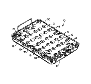
Figures 1-4 show a preferred embodiment of the apparatus of the present
invention
designated generally by the numeral 10. Grilling rack 10 is in the form of a
two part frame 11
which can be metallic (e.g., aluminum or stainless steel). Frame 11 has a
lower section 12 and an
upper section 13. Upper section 13 is a removable plate that can be perforated
or apertured.
The upper section or plate 13 can be in the form of a perforated plate that
can be removed
from the lower section 12 by lifting the upper section 13 upwardly. Lower
section 12 has a
corrugated bottom panel 20 (see figures 2-4) that has troughs 21 and peaks 22
(See figures 2-3).
Bottom panel 20 can be of a mesh material (e.g., stainless steel mesh) or of
solid plate metal
(e.g., stainless steel). Lower section 12 can be generally rectangular,
providing side walls 14, 15
and end walls 16, 17. Each end wall 16, 17 can be provided with a handle. End
wall 16 has a
handle 23. End wall 17 has a handle 24. Each trough 21 and peak 22 is
connected with an
inclined panel 25. (See figure 4.) While multiple troughs 21 are shown, a
single trough 21 could
-4-
CA 02775194 2012-04-20
be provided on an elongated lower section 12 having a single row of openings
19 in an upper
section 13 (as an alternate embodiment).
The upper section or plate 13 nests within the side walls 14, 15 and end walls
16, 17 and
rests upon the plurality of peaks 22 of corrugated bottom panel 20 (see
figures 1-3). The lower
section 12 can be of welded metal construction including troughs 21 which can
be formed of
sections of angle members, flanged members or the like that are welded
together. Alternatively,
a single sheet of material can be corrugated to the shape of lower section 12
using a stamp or die.
Each trough 21 has a trough 21 lower end 26 that is centered upon the center
27 of an
opening 19 as seen by referring to reference line 28 in figure 3. In this
fashion, when an
lo elongated food item (such as an elongated pepper 18) is placed in an
opening 19, the lower end
of the pepper 18 also registers in the V-shaped trough 21 and more
particularly in the lower
most portion 26 thereof (see figure 3).
When grilling stuffed elongated peppers (e.g., a jalapeno), the upper section
or plate 13 is
placed upon the lower section 12 (see figures 1-3). Notice in figure 3 that
the center 27 of each
opening 19 is vertically aligned with the lowest end 26 of a trough 21 as
indicated by the dotted
reference line 28 in figure 3. Lower end 29 of pepper 18 rests in lower end 26
of trough 21.
Circular edge 30 that defines each opening 19 engages and supports pepper 18
in between its
upper end 39 and lower end 29 as seen in figures 2-3. Upper section or plate
13 is shown having
an array of openings 19. In figures 1-2, there are seven rows of openings .19,
six openings 19 in
2o each row. However, more or fewer rows can be provided. Each row can provide
any selected
number of openings 19.
In figures 5-8, an alternate version of the grilling rack is designated by the
numeral IOA
in figures 5-6 and 8 and numeral IOB in figure 7. For the racks IOA-IOB, there
is no upper
section or plate 13.
In figures 5, 6, and 8, the rack 1 OA includes a pair of cylinders or
cylindrically shaped
members or receptacles 31. Each cylinder 31 has an open top 32 and an interior
33 for holding a
vegetable or other food item or a container of seasoning such as an opened can
34 of any selected
beverage. Rack I OB in figure 7 provides only cylinder 31. Each receptacle 31
is attached to
corrugated bottom panel 20. Receptacle 31 can be placed anywhere on the rack I
OA. Panel 20
can be a single sheet of corrugated material or a plurality of tapered or V-
shaped members
welded together. Corrugated panel 20 can have handles 23, 24 connected thereto
(e.g., welded).
-5-
CA 02775194 2012-04-20
The present invention provides an improved grilling rack apparatus that
enables a user to
cook many food items including elongated peppers that have been stuffed with a
filler or filling.
For the embodiment of figures 4-8, food item 35 such as poultry can be
supported upon (e.g.
skewered) a cylinder 31 that contains flavoring (e.g. opened can 34 of any
selected liquid or
spices or vegetables). Arrow 36 in figure 8 illustrates placement of can 34
within interior 33 of
cylinder 31 via open top 32. A food item 35 such as a chicken can be placed
over (e.g.,
skewered) the combination of opened can 34 and cylinder 31 as indicated by
arrows 37 in figure
8. Such final position of the food item (e.g., poultry carcass, chicken, etc.)
is designated as 38 in
figure 8 wherein the can 34 (or other spice or flavoring) occupies interior 33
of
lo cylinder/receptacle 31 and the food item 35 is skewered over both cylinder
31 and the contained
can 34 or spice or flavoring. Receptacle 31 can be placed anywhere on the rack
l OB.
Figures 9 - 11 show the food dispensing funnel, plunger, push rod. Figures 12 -
14
show the method of the present invention. In figure 11 there is a food
stuffing apparatus,
designated generally by the numeral 40. Food stuffing apparatus 40 includes a
receptacle or
funnel 41 that can contain a volume of a selected food stuffing 58 (e.g., rice
or cheese or meat
based stuffing or dressing). Receptacle 41 can be of metallic (e.g., stainless
steel) or plastic
(e.g., any food grade plastic) construction. This food stuffing or dressing 58
can be added to
interior 53 of receptacle 41 via an open top 44 at upper end portion 43. The
receptacle 41 has
upper end portion 43 and lower end portion 45. Tapered portion 47 joins upper
end portion 43 to
lower end portion 45. (See figures 9, 11.)
Upper end portion 43 can include a circular rim or edge 56. A dispensing
outlet opening
46 is provided at lower end portion 45. Receptacle 41 can be manually
supported and
manipulated using handle 42 which is attached to the outer surface of
receptacle 41 at
attachments 54, 55. (See figures 9, 11.)
Plunger 48 has head 49 with lower end portion 50. Head 49 has a circular,
generally flat
end surface 51. Plunger 48 has a handle 57 attached at joint 52 to plunger
head 49. Head 49 can
be generally cylindrically shaped or can have a taper as shown in figure 10.
Outlet opening 46
has a circular configuration that closely matches the size and shape of end
surface 51 of plunger
48. Outlet opening 46 can be of the same diameter or slightly larger in
diameter than plunger 48
surface 51. Head 49 is preferably of a food grade plastic or metal material.
Handle 57 can be of
wood, plastic or metal.
-6-
CA 02775194 2012-04-20
Figures 12-14 illustrate more particularly the method of the present
invention. In figures
12-14, there can be seen an array 67 of peppers 18 placed in grilling rack 10.
As shown in the
figures 1-8 and as discussed in the preceding, corresponding text, the
grilling rack 10 has a lower
section 12, upper section 13, a plurality of openings 19 and a corrugated
bottom panel 20. Each
pepper 18 is first cut using a knife to form a transverse cut 63 and a pepper
opening 64 through
which food stuffing can enter the pepper cavity 65. The cavity 65 extends
between pepper
opening 64 and lower end 66 as shown in figures 12 and 13.
After each pepper 18 is cut to provide the pepper opening 64 and to expose
cavity 65, the
pepper 18 is placed on rack 10 with opening 64 facing up as shown in figure
14. Once each of
the openings 19 of rack 10 is fitted with a pepper 18 as shown in figure 14, a
user fills each
pepper 18 cavity 65 with food stuffing 58 of the user's choice. During the
filling of each pepper
18 cavity 65 with food stuffing 58, a user positions one hand 61 to hold the
handle 42 of
receptacle or funnel 41. The user grasps plunger 48 with the other hand 60 as
shown in figure
14. An up and down movement of the plunger 48 relative to the receptacle 41
forces the stuffing
58 through the cylindrically shaped channel 62 at lower end portion 45 of
receptacle 41.
Figure 12 illustrates a downward movement of plunger 48 as indicated by arrow
59
wherein stuffing 58 is pushed by plunger head 49 through lower end 45, through
channel 62, and
into pepper 18 cavity 65. Note in figure 12 that the lower end portion 45 of
receptacle 41 is
sized and shaped to fit inside of pepper 18 lower end of cavity 66. The
external diameter of
lower end portion 45 at dispensing outlet opening 46 is preferably about the
same diameter or is
a smaller diameter when compared to the diameter of pepper opening 64. This
arrangement can
be seen in figures 12 and 13.
By using the method of the present invention, a user can prepare an entire
array 67 of
peppers upon grilling rack 10 for placement in a cooking device, oven,
barbeque pit, or the like.
The method of the present invention enables an entire array 67 of peppers to
be supported
in a position that places the lower end portion of the pepper in trough 21 of
grilling rack 10 while
orienting the transversely cut pepper opening 64 upwardly. In this fashion,
the opening 64 easily
receives lower end portion 45 and opening 46 of receptacle 41 as shown in
figure 12. The user
raises and lowers the plunger 48 repeatedly to push food stuffing into
cylindrically shaped
channel 62 and then into cavity 65 until the pepper 18 cavity 65 is filled
with stuffing as shown
in figures 12 and 13. In figure 14, most of the peppers 18 have been stuffed
with food stuffing
-7-
CA 02775194 2012-04-20
58. A final row at 68 shows six peppers 18 that have not yet been filled with
food stuffing 58.
Once the user fills the cavity 65 of each pepper 18, the array 67 of peppers
supported upon rack
are placed in heat transfer contact with a selected cooking device, smoker,
camp fire,
barbeque pit, oven or the like.
5 PARTS LIST:
The following is a list of parts and materials suitable for use in the present
invention:
Parts Number Description
10 grilling rack
10 10A grilling rack
10B grilling rack
11 frame
12 lower section
13 upper section/plate
14 side wall
15 side wall
16 end wall
17 end wall
18 pepper
19 opening
20 corrugated bottom panel
21 trough
22 peak
23 handle
24 handle
25 inclined panel
26 lower end
27 center of opening
28 reference line
29 lower end
30 circular edge
-8-
CA 02775194 2012-04-20
31 cylinder/receptacle
32 open top
33 interior
34 can
35 food item
36 arrow
37 arrow
38 position
39 upper end
40 food stuffer/food stuffing
apparatus
41 receptacle/funnel
42 handle
43 upper end portion
44 open top
45 lower end portion
46 dispensing outlet opening
47 tapered portion
48 plunger
49 plunger head
50 lower end portion
51 flat, circular end surface
52 joint
53 interior
54 attachment
55 attachment
56 rim/edge
57 handle
58 food stuffing
59 arrow
60 user's hand
-9-
CA 02775194 2012-04-20
61 user's hand
62 cylindrically shaped channel
63 transverse cut
64 pepper opening
65 cavity
66 lower end of cavity
67 array of peppers
68 final row
All measurements disclosed herein are at standard temperature and pressure, at
sea level
on Earth, unless indicated otherwise. All materials used or intended to be
used in a human being
are biocompatible, unless indicated otherwise.
The foregoing embodiments are presented by way of example only; the scope of
the
present invention is to be limited only by the following claims.
-10-