Note: Descriptions are shown in the official language in which they were submitted.
CA 02775298 2013-04-22
SYSTEM AND ASSOCIATED NFC TAG USING PLURALITY OF NFC TAGS
ASSOCIATED WITH LOCATION OR DEVICES TO COMMUNICATE
WITH COMMUNICATIONS DEVICE
Cross¨Reference to Related Application
This application claims the benefit of and priority to
European Patent Application Serial No. 09171264.6 filed
September 24, 2009 under the title SYSTEM AND
ASSOCIATED NFC TAG USING PLURALITY OF NFC TAGS ASSOCIATED
WITH LOCATION OR DEVICES TO COMMUNICATE WITH
COMMUNICATIONS DEVICE.
Technical Field
[0001] This application
relates to the field of
communications, and more particularly, to mobile
wireless
communications devices and related methods that use Near
Field Communications (NFC).
Background
[0002] Mobile communication systems continue to grow
in popularity and have become an integral part of both
personal and business communications. Various mobile
devices now incorporate Personal Digital Assistant (PDA)
features such as calendars, address books, task lists,
calculators, memo and writing programs, media players,
games, etc. These multi-function devices usually allow
users to send and receive electronic mail (email) messages
wirelessly and access the internet via a
1
CA 02775298 2012-03-23
WO 2011/035413 PCT/CA2010/001477
2
cellular network and/or a wireless local area network
(WLAN), for example.
[0003] Some mobile devices incorporate contactless
card technology and/or Near Field Communication chips.
Near Field Communications technology is commonly used for
contactless short-range communications based on radio
frequency identification (RFID) standards, using magnetic
field induction to enable communication between
electronic devices, including mobile wireless
communications devices. These short-range communications
include payment and ticketing, electronic keys,
identification, device set-up service and similar
information sharing. This short-range high frequency
wireless communications technology exchanges data between
devices over a short distance, such as only a few
centimeters.
[0004] As Near Field Communication (NFC) technology
becomes more commonplace, it is often used with portable
wireless communications devices in association with other
short-range wireless communications such as a wireless
Bluetooth connection. For example, an NFC connection is
often used to establish a wireless Bluetooth connection
in which data for establishing the Bluetooth connection
is communicated.
Summary
[0005] A Near Field Communications (NFC) tag includes
a housing and a magnet carried by the housing and
configured to be magnetically sensed by a magnetic sensor
carried by a communications device to activate an NFC
circuit within the communications device to communicate
using an NFC communications protocol. A data store
CA 02775298 2012-03-23
WO 2011/035413 PCT/CA2010/001477
3
stores data regarding a function of the communications
device to be magnetically coupled by the magnet. The data
store is configured to be read by the communications
device using an NFC communications protocol after the NFC
circuit had been activated.
Brief Description of the Drawings
[0006] Other objects, features and advantages of the
present invention will become apparent from the detailed
description of the invention which follows, when
considered in light of the accompanying drawings in
which:
[0007] FIGS. 1-7 show an example of first and second
mobile wireless communications devices in accordance with
a non-limiting example in a device-to-device
communication and showing the establishment of
communications by sensing a magnet using a Hall Effect
sensor, for example, to activate the Near Field
Communications circuits and establish a higher-level
communication protocol such as a Bluetooth wireless
connection in accordance with a non-limiting aspect.
[0008] FIG. 8 is a high-level block diagram showing
basic components of a portable wireless communications
device that can incorporate the functionality for either
device-to-device communication or a device-tag
communication in accordance with a non-limiting aspect as
shown in FIGS. 9-19.
[0009] FIGS. 9-19 are examples of a device-tag
communication and showing an example of a portable
wireless communications device and NFC tag as a business
cardholder using its magnet to activate a Near Field
Communication circuit for data transfer.
CA 02775298 2012-03-23
WO 2011/035413 PCT/CA2010/001477
4
[0010] FIG. 20 is a fragmentary view of an office
environment showing numerous passive tags located
throughout the office.
[0011] FIG. 21 is a front elevation view of a printer
showing a passive tag connected thereto.
[0012] FIG. 22 shows two communications devices that
use an electromagnet in a kiss gesture.
[0013] FIG. 23 is a perspective view of a
communications device looking at the top with the top end
cap removed and showing the magnet, magnetic sensor and
antenna positioned at the top.
[0014] FIG. 24 is a fragmentary perspective view
showing connection between the communications device and
a projector using a tag located on the projector to
implement the connection.
[0015] FIG. 25 is a fragmentary perspective view
showing a tag attached at a subway terminal to link a
user to schedules through a connection with the
communications device.
[0016] FIG. 26 is a fragmentary perspective view of a
communications device connected to a computer by
implementing the connection using a tag.
[0017] FIG. 27 is a fragmentary perspective view
showing a communications device connected to access media
as a media alternative with connection established using
a tag.
[0018] FIG. 28 is a timing diagram showing time for
the kiss gesture, magnetic detection, NFC and Bluetooth.
[0019] FIG. 29 is an example of a communications
device that uses an accelerometer to initiate NFC
communications.
CA 02775298 2012-03-23
WO 2011/035413 PCT/CA2010/001477
Detailed Description
[0020] Different embodiments will now be described
more fully hereinafter with reference to the accompanying
drawings, in which various embodiments are shown. Many
5 different forms can be set forth and described
embodiments should not be construed as limited to the
embodiments set forth herein. Rather, these embodiments
are provided so that this disclosure will be thorough and
complete, and will fully convey the scope to those
skilled in the art. Like numbers refer to like elements
throughout.
[0021] A drawback of some devices and systems that
incorporate NFC and/or Bluetooth circuits is a
requirement that the NFC and/or Bluetooth circuits are
constantly on. This creates a power-draining circuit.
Furthermore, in some cases could, this result in unwanted
connections.
[0022] A communications device establishes wireless
communications between communications devices and a
device-to-device communication in one non-limiting
example. Respective magnets and magnetic sensors are
aligned and each are located on first and second
communications devices such that a magnet on the first
communications device is aligned with a magnetic sensor
on the second communications device and a magnet on the
second communications device is aligned with the magnetic
sensor on the first communications device. A Near Field
Communications (NFC) circuit contained in each of the
first and second communications devices and at least one
is activated in response to sensing the magnet on the
respective other communications device. Data is
CA 02775298 2012-03-23
WO 2011/035413
PCT/CA2010/001477
6
exchanged between the first and second communications
devices using a NFC communications protocol.
[0023] In accordance with another aspect, the two
communications devices are in physical contact for
activating the NFC circuits within respective
communications devices. In another aspect, the two
communications devices are within a few millimeters for
activating the NFC circuits within respective
communications devices. In another example, a wireless
communications connection is established different than
NFC between first and second communications devices based
on data exchanged between first and second communications
devices.
[0024] A personal identification number (PIN) and
security key are exchanged between first and second
communications devices using NFC for establishing a
wireless communications connection in another non-
limiting aspect. A wireless communications connection
can be established using Bluetooth communications
protocol or WiFi communications protocol.
[0025] In another aspect, the magnetic sensor uses the
Hall Effect sensor located within a respective
communications device. A processor can sense voltage
variations produced by the Hall Effect to determine that
the NFC circuit should be activated.
[0026] A communications device includes a housing and
a circuit board carried by the housing. Radio frequency
(RF) circuitry and a processor are carried by the
housing, such as on a circuit board, and operative with
each other. A Near Field Communications (NFC) circuit is
positioned on the circuit board and connected to the
processor for communicating using a NFC communications
CA 02775298 2012-03-23
WO 2011/035413
PCT/CA2010/001477
7
protocol. A magnetic sensor, such as a Hall Effect
sensor, is supported by the housing and connected to the
processor for sensing a magnetic field and generating a
signal to the processor, and in response, the processor
activating the NFC circuit for transmitting or receiving
data using NFC communications protocol.
[0027] Other method aspects are set forth.
[0028] FIG. 1 shows an example of two similar portable
wireless communications devices 20,22 that are brought
together in a "gesture" as a physical movement towards
each other into very close or actual physical contact to
provide a simple interface and initiate a wireless
connection. This physical gesture of moving a device
into contact with the other device provides a more simple
and lower-powered system and method of establishing a
wireless connection, such as triggering the Hall Effect,
which triggers the Near Field Communication (NFC), which
could trigger a Bluetooth or WiFi wireless connection.
In one non-limiting example, each device 20,22 is
provided with a magnet 24 and an environment sensor 26
such as a Hall Effect sensor. Each is matched in a
single touch or gesture, also termed a "kiss" gesture
because the two devices 20,22 typically touch or "kiss"
each other or are very close and in adjacent proximity.
An example could be in the range of about less than 10 or
20 mm, depending on the strength of the magnets, and in
one example, when it is about 7 mm or less from the tag
or device. The sensor 26 on each device is aligned to
the magnet on the respective other device, as illustrated
in FIG. 1. One device senses ("sees") the other magnet
via the Hall Effect, and a signal or voltage variation
from the sensor is transmitted to a processor, which
CA 02775298 2012-03-23
WO 2011/035413
PCT/CA2010/001477
8
activates a Near Field Communication (NFC) circuit and
communicates using the NFC communication protocol with
the other device. The devices can then read data from
each other using NFC. Communications protocol data for a
wireless connection, such as the Bluetooth connection can
be obtained based on data received using the NFC
connection. For example, PIN numbers and security keys
could be exchanged using NFC to establish a Bluetooth
connection.
[0029] As will be explained in detail below, it is
possible for one communications device 20 to establish
communication with a passive peripheral by touching the
device to a passive magnetic tag (NFC tag in this
example), thus initiating a NFC connection with the
peripheral. Passive magnetic tag could refer to
different devices, including NFC tags or business
cardholders or other data storage devices with limited
transmit capability. If the tag is blank (for example, a
business cardholder), the tag can be programmed in some
cases. If the tag is already programmed, the
communications device can read information from the tag,
which may lead to further action. For example, if the
tag is associated with a printer, the communications
device can run a print job on the printer, as discussed
further below. An advantage of such system is the Hall
Effect is entirely passive, which avoids the requirement
for the mobile wireless communications device to have the
NFC or Bluetooth circuit constantly "on" and thus drawing
power. Only when the communications device 20 determines
("sees") the presence of another magnet such as on
another communications device 22 or passive tag, the
device 20 will trigger the initiation of a wireless NFC
CA 02775298 2012-03-23
WO 2011/035413 PCT/CA2010/001477
9
or Bluetooth connection. An additional benefit is that
the Hall Effect requires a closer contact than the NFC
circuit, meaning that a deliberate "gesture" is required,
such as touching the two communications devices together.
This avoids accidental or invasive connections when other
Bluetooth-enabled devices are in the area. The term tag
as used above can include various devices, which
typically operate passively instead of operating in an
active mode as with the communications devices 20,22.
[0030] As illustrated, each communications device
20,22 in this example for a device-to-device
communication as shown in FIGS. 1-7 includes a housing
30, keyboard 32, and display 34, which could operate as a
touch display in one example. As noted above, each
device includes a magnetic sensor 26, for example, a Hall
Effect sensor in this non-limiting example and a magnet
24. The sensor 26 and magnet 24 work together to
activate any NFC circuits in each device for exchanging
data.
[0031] Near Field Communication (NFC) technology is an
extension of the ISO 14443 proximity-card standard as a
contactless card, RFID standard that incorporates the
interface of a smart card and a reader into one device.
A NFC device such as a mobile phone or other mobile
wireless communications device typically includes an NFC
integrated circuit (IC) chip that communicates to such
devices as existing ISO 14443 smart cards and readers and
other NFC devices and compatible with any existing
contactless infrastructure. The NFC IC chips use
magnetic field induction where two loop antennas are
located near each other and form an air-core transformer.
The technology operates on the unlicensed radio frequency
CA 02775298 2012-03-23
WO 2011/035413
PCT/CA2010/001477
ISM band of about 13.56 MHz and has a bandwidth of about
2 MHz. The working distance is usually about 0 to 20
centimeters. A user of the NFC device brings one NFC
enabled device close to another NFC enabled device or tag
5 to initiate NFC communication, with data rates ranging
from 106 to about 424 kbit/s.
[0032] There are different modes of operation. Most
mobile wireless communications devices operate in an
active communications mode using a modified Miller and
10 100% amplitude shift keyed (ASK) code unless a passive
mode is used in which a Manchester and ASK code is used.
Further details are set forth in the Mobile NFC Technical
Guidelines, Version 2.0, November 2007 by GSMA, the
disclosure of which is hereby incorporated by reference
in its entirety.
[0033] The "Near Field Communications Interface and
Protocol" or "NFCIP-1" or "the NFC protocol" also allows
for communication between an initiator device and a
target device, when the initiator device and the target
device are brought close together. In the example above,
the communications device 20 can be an initiator and a
printer or business cardholder could be the target
device, and operate as a passive device. Magnets could
be sensed using the sensor 26 and the NFC circuit in
device 20 activated. Detailed information about NFCIP-1
is available in a published standard called ECMA-340,
which is available from Ecma International at
www.ecma-international.org.
[0034] The NFC protocol operates within the globally
available and unregulated radio frequency band of 13.56
MHz and has a working distance of up to 20 centimeters.
Three data rates are typically available: 106 kilobits
CA 02775298 2012-03-23
WO 2011/035413 PCT/CA2010/001477
11
per second (kbit/s), 212 kbit/s, and 424 kbit/s. As
noted before, multiple modes of communication are
currently available. In the passive communication mode,
the initiator device provides an electromagnetic carrier
field and the target device answers the initiator device
by modulating the carrier field. In the passive
communication mode, the target device may draw operating
power from the carrier field provided by the initiator
device. Advantageously, only the initiator device is
required to have a power supply. The modulating magnetic
field created by the target device could be used for
communicating a limited amount of data.
[0035] In the active communication mode, both the
initiator device and the target device generate their own
electromagnetic field, such as in the example using the
communications devices 20,22. The initiator device
starts the NFCIP-1 communication. The target device can
respond to a command received from the initiator device
in the active communication mode by modulating the
electromagnetic field generated by the target device.
Typically, in the active communication mode, both devices
require a power supply.
[0036] Notably, in the active communication mode, both
devices can act as either initiator or target, while this
is not the case in the passive communication mode,
wherein the device without the ability to create an
electromagnetic carrier field cannot be an initiator
device and instead becomes the target device.
[0037] According to NFCIP-1, responsive to sensing
modulation of the initiator electromagnetic carrier field
by the target device, the initiator device performs an
initial collision avoidance sequence by transmitting an
CA 02775298 2012-03-23
WO 2011/035413
PCT/CA2010/001477
12
ATR_REQ (attribute request) command to the target device.
Responsive to receiving the ATR_REQ (attribute request)
command, the target device transmits a response called
ATR_RES (attribute response).
[0038] Referring again to FIG. 1 and more particularly
to the device-to-device sequence shown in FIGS. 1-7, the
device-to-device communication allows a user of a
portable wireless communications device 20 as illustrated
to share media or data content with another
communications device 22 in an easy and secure manner.
Such media or data could include photographs, address
book exchanges, instant messages, music or other audio,
video, stored information such as related to a grocery
store, tickets, movie theater data, or coupons, as non-
limiting examples. This audio could include voice or
personal sound recordings that one might make into ring
tones, as an example.
[0039] As shown in FIG. 1, each portable wireless
communications device 20,22 includes a top or upper
section 36 that supports the magnet 24 and magnetic
sensor 26 and associated sensing circuitry embedded in
the top of the device in one non-limiting example. As
the two communications devices 20,22 approach each other
(touch each other typically), their respective magnetic
fields are detected through their magnetic sensors as
Hall Effect sensors and associated circuitry and the Near
Field Communication (NFC) circuit in each communications
device are activated to allow subsequent and more
complicated data exchange. It is possible to integrate
the NFC / magnet into a skin / battery door of a device.
For example, an older device will still broadcast a
Bluetooth name / security code to another device, but a
CA 02775298 2012-03-23
WO 2011/035413 PCT/CA2010/001477
13
user would still have to enter their information
manually. Without some type of communication between the
NFC portion and the host processor, this function may be
limited. If a skin is connected as a host via USB (or a
slave if the USB-on-the-go is implemented) and the NFC is
connected, it is possible to gain full function. In this
example, however, it may require its own separate power
supply. FIG. 2 shows both devices approaching each other
and the respective magnetic fields from the aligned
magnet and Hall Effect sensors in operation.
[0040] FIG. 3 shows both devices 20,22 touching each
other in what is also called the "kiss" gesture, in which
the Hall Effect sensors 26 are operable and aligned to
activate the NFC circuits by touching the two devices
together. As shown in FIG. 3, the NFC circuit is thus
activated and data is exchanged between devices such as
security codes, IDs or PINs to establish a higher level
communications protocol between the two devices, such as
initiating a Bluetooth wireless connection as shown in
FIG. 4, in which a pop-up screen 34a on one or both of
the displays of the communications devices states that BT
(Bluetooth) pairing is in progress. Once the Bluetooth
connection is established, the devices can be separated
as shown in FIG. 5 and allow further data transfer of
greater quantities using Bluetooth connections instead of
the limited data transferred by NFC for initiating a
Bluetooth connection. FIG. 6 shows that the display 34
on one of the devices has an indicator logo 34b
indicating that the device is Bluetooth connected to the
other device. As shown in FIG. 7 with the devices 20,22
now connected via a Bluetooth connection, the users (Ul
and U2) are free to share their device content and
CA 02775298 2012-03-23
WO 2011/035413
PCT/CA2010/001477
14
transfer data or other content as desired, for example,
exchange addresses, photographs, video or other
information.
[0041] In operation, a Hall Effect sensor operates
similar to a transducer that varies its output voltage in
response to changes in magnetic field, and thus, acts as
a passive sensor. This type of sensor can be used for
proximity sensing when two devices are brought together,
such as the devices 20,22 shown in FIG. 3. A magnetic
field is produced in the circuit that varies with
current. The Hall Effect sensor measures the current
without interrupting the circuit. In one example, a
sensor is integrated with a wound core or permanent
magnet that surrounds a conductor to be measured,
operating as a switch in a digital on/off mode. It is
connected to an NFC circuit via a processor in the device
to switch the NFC circuit on. For example, the processor
in the wireless device could determine voltage variations
indicative of the "kiss" gesture, i.e., devices touching,
and thus send a signal to the NFC circuit activating that
circuit.
[0042] Bluetooth, on the other hand, is an open
wireless protocol that exchanges data over short
distances (but longer than NFC) from fixed and mobile
devices, creating what is essentially a Personal Area
Network (PAN). A wireless Bluetooth connection typically
communicates using a frequency-hopping spread spectrum
signal and up to 79 different frequencies. In one
modulation, it is a Gaussian Frequency-Shift Keying
(GFSK) system that can achieve a gross data rate of up to
1 Mb/s. It is short range and is power-class-dependent
of up to one meter, ten meters or 100 meters depending on
CA 02775298 2012-03-23
WO 2011/035413
PCT/CA2010/001477
the type of transceiver microchip used in communications
devices. Typically, modern communications devices will
allow Bluetooth communication of up to 100 meters in non-
limiting examples.
5 [0043] A non-limiting example of various functional
components that can be used in the exemplary mobile
wireless communications device 20 is further described in
the example below with reference to FIG. 8. New
reference numerals are used. Device 100 is an example
10 embodiment of devices 20,22. The device 100
illustratively includes a housing 120, a keypad 140 and
an output device 160. The output device 160 shown may
comprise a display, which may comprise a full graphic LCD
and may be touch sensitive as an input device. Other
15 types of output devices may alternatively be used. A
processing device 180 is contained within the housing 120
and is coupled between the keypad 140 and the display
160. This device 180 is typically a microprocessor chip
contained on a circuit board in the housing 120. If the
display is a touch-activated display, the keypad 140 may
not be necessary. The processing device 180 controls the
operation of the display 160, as well as the overall
operation of the mobile device 100, in response to
actuation of keys on the keypad 140 by the user.
[0044] The housing 120 may be elongated vertically, or
may take on other sizes and shapes (including clamshell
housing structures). The keypad may include a mode
selection key, or the device may include other hardware
or software for switching between text entry and
telephony entry.
[0045] In addition to the processing device 180, other
parts of the mobile device 100 are shown schematically in
CA 02775298 2012-03-23
WO 2011/035413 PCT/CA2010/001477
16
FIG. 8. These include a communications subsystem 101; a
short-range communications subsystem 102; the keypad 140
and the display 160, along with other input/output
devices 106, 108, 110 and 112; as well as memory devices
116, 118 and various other device subsystems 121. The
mobile device 100 is in this example a two-way RF
communications device having voice and data
communications capabilities using RF circuitry. In
addition, the mobile device 100 has the capability to
communicate with other computer systems via the Internet.
The short-range communications subsystem 102 includes a
Bluetooth (BT) communications module for establishing a
Bluetooth wireless connection and other communications
modules such as an infrared module or device, WiFi
circuit and module, and associated components and
circuits as part of RF circuitry.
[0046] Operating system software executed by the
processing device 180 may be stored in a persistent
store, such as the flash memory 116, or may be stored in
other types of memory devices, such as a read only memory
(ROM) or similar storage element. In addition, system
software, specific device applications, or parts thereof,
may be temporarily loaded into a volatile store, such as
the random access memory (RAM) 118. Communications
signals received by the mobile device may also be stored
in the RAM 118.
[0047] The processing device 180, in addition to its
operating system functions, enables execution of software
applications 130a-130n on the device 100. A
predetermined set of applications that control basic
device operations, such as data and voice communications
130a and 130b, may be installed on the device 100 during
CA 02775298 2012-03-23
WO 2011/035413 PCT/CA2010/001477
17
manufacture. A Near Field Communications module 130C is
also installed as illustrated.
[0048] The NFC communications module 130c as a
software module cooperates with the microprocessor 180
through the flash memory 116. The microprocessor 180
operates also with the NFC subsystem 132 that includes a
NFC chip 132a and antenna 132b that communicates with
another device/tag 133 such as the type shown in FIGS. 1-
7. The NFC communications module 130c allows the
microprocessor to control the NFC subsystem 132, which
includes the NFC chip 132a and antenna 132b that is tuned
typically for 13.56 MHz. The NFC chip 132a could be, for
example, a PN531 microcontroller-based transmission
module from the Phillips Semiconductor Branch of
Koninklijke Phillips Electronics N.V. When the NFC chip
is a PN531 module, the NFC chip 132a could include analog
circuitry and a contact list Universal Asynchronous
Receiver Transmitter (UART), a core and a set of host
interfaces. The analog circuitry could include an output
driver, an integrated demodulator, a bit decoder, a mode
detector and an RF-level detector. The contact list UART
could include elements for data processing, Cyclical
Redundancy Checking (CFC), parity generation, framing
generation and check bit coding and decoding. The core
typically includes an 80051 microcontroller, 32 Kbyte of
ROM and one Kbyte of RAM. A set of host interfaces can
interface with the microprocessor and interface according
to such known standards as I2C, serial UART, SPI and USB.
[0049] There is also illustrated the magnetic sensor
134 that could be formed as a Hall Effect sensor and is
connected to the microprocessor 180. It includes the
various components that operate as a Hall Effect sensor,
CA 02775298 2012-03-23
WO 2011/035413 PCT/CA2010/001477
18
including any necessary coils or other circuits. There
is also illustrated a magnet 135 that, in one example, is
formed as an electromagnet and operates with the
microprocessor to allow a different communications
pathway using electromagnetic energy that is changed to
correspond to changing data. The electromagnet 135
operates similar to the magnet 24 as shown in the mobile
wireless communications device in FIGS. 1-7, but
operates, in one example, to form another communications
protocol pathway. This electromagnet 135 has different
functions, including working as an active or passive
device in association with other components of the device
100 as illustrated. For example, when the electromagnet
135 is used in place of an installed magnet (non-
electromagnetic) in the devices of FIG. 1, a pulse of
energy is delivered to the Hall Effect sensor in the
other device. The other device receives the pulse and
establishes a Bluetooth connection without going through
activation of the NFC circuit. A WiFi connection, for
example, in the alternative is established if a Bluetooth
connection is not established. Other software modules
130n include software that interoperates with the
magnetic sensor 134 and any magnet or electromagnet 135
or other magnetic circuitry that are included within the
overall electromagnet 135.
[0050] An accelerometer 137 and an analog/digital
converter 138 are connected to the microprocessor 180 as
illustrated and allow another implementation of the NFC
automatic tag detection (and automatic peer-to-peer
detection). The accelerometer 137 recognizes the tapping
of a communications device against a tag or another
device, i.e., recognizes the vibrations. Instead of
CA 02775298 2012-03-23
WO 2011/035413 PCT/CA2010/001477
19
using the Hall effect sensors and magnets to wake up the
NFC circuit, the circuit uses tap recognition, for
example, as a vibration sensor and accelerometer in this
example. It should be understood that when the device is
tapped against another object, for example, an NFC tag, a
profile is generated as a matter of certain accelerometer
parameters being met or exceeded. If the profile is
compared against a known tap profile, it will wake the
NFC circuit and initiate communication. In other
embodiments, the accelerometer could be part of a motion
sensor system and other motion sensor systems other than
an accelerometer could be used such as a cadence sensor
or cadence detection system.
[0051] As will be appreciated by persons skilled in
the art, an accelerometer is a sensor which converts
acceleration from motion (e.g., movement of the
communications device or a portion thereof due to the
strike force) and gravity which are detected by a sensing
element into an electrical signal (producing a
corresponding change in output) and is available in one,
two or three axis configurations. Accelerometers may
produce digital or analog output signals depending on the
type of accelerometer. Generally, two types of outputs
are available depending on whether an analog or digital
accelerometer is used: (1) an analog output requiring
buffering and analog-to-digital (AID) conversion; and (2)
a digital output which is typically available in an
industry standard interface such as an SPI (Serial
Peripheral Interface) or I2C (Inter-Integrated Circuit)
interface. The embodiment shown in FIG. 8 illustrates an
analog output into the AID converter 138. The output of
an accelerometer is typically measured in terms of the
CA 02775298 2012-03-23
WO 2011/035413
PCT/CA2010/001477
gravitational acceleration constant at the Earth's
surface, denoted g, which is approximately 9.81 m/s2
(32.2 ft/s2) as the standard average. The accelerometer
may be of almost any type including, but not limited to,
5 a capacitive, piezoelectric, piezoresistive, or gas-based
accelerometer. The range of accelerometers varies up to
the thousands of g's, however for portable electronic
devices "low-g" accelerometers may be used. Example low-
g accelerometers which may be used are MEMS digital
10 accelerometers from Analog Devices, Inc. (ADI), Freescale
Semiconductor, Inc. (Freescale) and STMicroelectronics
N.V. of Geneva, Switzerland.
[0052] The operational settings of the accelerometer,
in one example, are controlled using control signals sent
15 to the accelerometer via a serial interface. In one
illustrated example, the microprocessor determines the
motion detection in accordance with the acceleration
measured by the accelerometer. Raw acceleration data
measured by the accelerometer, in another example, is
20 sent to the microprocessor via a serial interface where
motion detection is determined by the operating system or
other software module. In other embodiments, a different
digital accelerometer configuration could be used, or a
suitable analog accelerometer and control circuit could
be used.
[0053] In addition, a personal information manager
(PIN) application may be installed during manufacture.
The PIN is capable of organizing and managing data items,
such as email, calendar events, voice mails,
appointments, and task items. The PIM application is also
capable of sending and receiving data items via a
wireless network 141. The PIN data items are seamlessly
CA 02775298 2012-03-23
WO 2011/035413 PCT/CA2010/001477
21
integrated, synchronized and updated via the wireless
network 141 with the device user's corresponding data
items stored or associated with a host computer system.
[0054] Communication functions, including data and
voice communications, are performed through the
communications subsystem 101, and possibly through the
short-range communications subsystem 120, which are part
of RF circuitry contained on a circuit board typically as
shown by the outline. The communications subsystem 101
includes a receiver 150, a transmitter 152, and one or
more antennae 154 and 156. In addition, the
communications subsystem 101 also includes a processing
module, such as a digital signal processor (DSP) 158, and
local oscillators (L0s) 161 as part of RF circuitry in
this example. The specific design and implementation of
the communications subsystem 101 is dependent upon the
communications network in which the mobile device 100 is
intended to operate. For example, the mobile device 100
may include a communications subsystem 101 designed to
operate with the Mobitexm, Data TACm or General Packet
Radio Service (GPRS) mobile data communications networks,
and also designed to operate with any of a variety of
voice communications networks, such as AMPS, TDMA, CDMA,
PCS, GSM, etc. Other types of data and voice networks,
both separate and integrated, may also be used with the
mobile device 100.
[0055] Network access requirements vary depending upon
the type of communication system. For example, in the
Mobitex and DataTAC networks, mobile devices are
registered on the network using a unique personal
identification number or PIN associated with each device.
In GPRS networks, however, network access is associated
CA 02775298 2012-03-23
WO 2011/035413
PCT/CA2010/001477
22
with a subscriber or user of a device. A GPRS device
therefore typically utilizes a subscriber identity
module, commonly referred to as a SIM card, in order to
operate on a GPRS network.
[0056] When required network registration or
activation procedures have been completed, the mobile
device 100 sends and receives communications signals over
the communication network 141. Signals received from the
communications network 141 by the antenna 154 are routed
to the receiver 150, which provides for signal
amplification, frequency down conversion, filtering,
channel selection, etc., and may also provide analog to
digital conversion. Analog-to-digital conversion of the
received signal allows the DSP 158 to perform more
complex communications functions, such as demodulation
and decoding. In a similar manner, signals to be
transmitted to the network 141 are processed (e.g.,
modulated and encoded) by the DSP 158 and are then
provided to the transmitter 152 for digital to analog
conversion, frequency up conversion, filtering,
amplification and transmission to the communication
network 141 (or networks) via the antenna 156.
[0057] In addition to processing communications
signals, the DSP 158 provides for control of the receiver
150 and the transmitter 152. For example, gains applied
to communications signals in the receiver 150 and
transmitter 152 may be adaptively controlled through
automatic gain control algorithms implemented in the DSP
158.
[0058] In a data communications mode, a received
signal, such as a text message or web page download, is
processed by the communications subsystem 101 and is
CA 02775298 2012-03-23
WO 2011/035413 PCT/CA2010/001477
23
input to the processing device 180. The received signal
is then further processed by the processing device 180
for an output to the display 160, or alternatively to
some other auxiliary I/O device 106. A device user may
also compose data items, such as e-mail messages, using
the keypad 140 and/or some other auxiliary I/O device
106, such as a touchpad, a trackball, a trackpad, a
rocker switch, a thumb-wheel, or some other type of input
device. The composed data items may then be transmitted
over the communications network 141 via the
communications subsystem 101.
[0059] In a voice communications mode, overall
operation of the device is substantially similar to the
data communications mode, except that received signals
are output to a speaker 110, and signals for transmission
are generated by a microphone 112. Alternative voice or
audio I/O subsystems, such as a voice message recording
subsystem, may also be implemented on the device 100. In
addition, the display 160 may also be used in voice
communications mode, for example to display the identity
of a calling party, the duration of a voice call, or
other voice call related information and whether there
are NFC communications or a Bluetooth connection.
[0060] Any short-range communications subsystem
enables communication between the mobile device 100 and
other proximate systems or devices, which need not
necessarily be similar devices. For example, the short-
range communications subsystem may include an infrared
device and associated circuits and components as
described above, or a Bluetooth communications module to
provide for communication with similarly-enabled systems
and devices as well as the NFC communications.
CA 02775298 2012-03-23
WO 2011/035413 PCT/CA2010/001477
24
[0061] In accordance with various embodiments, GSM is
an exemplary communications system and uses a radio
interface that can have an uplink frequency band and
downlink frequency band with about 25 MHz bandwidth,
typically subdivided into 124 carrier frequency channels,
each spaced about 200 KHz apart as non-limiting examples.
Time division multiplexing is usually used to allow about
8 speech channels per radio frequency channel, giving 8
radio time slots and 8 burst periods grouped into what is
called a TDMA frame. For example, a channel data rate is
typically about 270.833 Kbps and a frame duration of
about 4.615 milliseconds (MS) in one non-limiting
example. The power output usually varies from about 1 to
about 2 watts.
[0062] Typically, linear predictive coding (LPC) is
used to reduce the bit rate and provide parameters for a
filter to mimic a vocal track with speech encoded at
about 13 Kbps. Four different cell sizes are typically
used in a GSM network, including macro, micro, pico and
umbrella cells. A base station antenna is typically
installed on a master building above the average rooftop
level in a macrocell. In a microcell, the antenna height
is typically under the average rooftop level and used in
urban areas. Microcells typically have a diameter of
about a few dozen meters and are used indoors. Umbrella
cells usually cover shadowed regions or smaller cells.
Typically, the longest distance for the GSM specification
covered by an antenna is about 22 miles depending on
antenna height, gain and propagation conditions.
[0063] GSM systems typically include a base station
subsystem, a network and switching subsystem, and a
General Packet Radio Service (GPRS) core network. A
CA 02775298 2012-03-23
WO 2011/035413 PCT/CA2010/001477
subscriber identity module (SIM) is usually implemented
in the communications device, for example, the well-known
SIM card, similar to a smart card containing the
subscription information and phone book of a user. The
5 user typically switches handsets or could change
operators by changing a SIM. USIM, RUIM or CSIM and
other similar technologies can be used in UMTS or CDMA
networks.
[0064] The GSM signaling protocol has three general
10 layers. Layer 1 is a physical layer using channel
structures above the air interface. Layer 2 is the data
link layer. Layer 3 is a signaling protocol, which
includes three sublayers. These include a Radio
Resources Management sublayer to control the setup,
15 maintenance and termination of radio and fixed channels,
including handovers. A Mobility Management sublayer
manages the location updating and registration procedures
and secures the authentication. A Connection Management
sublayer handles general call control and manages
20 supplementary services and the short message service.
Signaling between different entities such as the Home
Location Register (HLR) and Visiting Location Register
(VLR) can be accomplished through a Mobile Application
Part (MAP) built upon the Transaction Capabilities
25 Application Part (TCAP) of the top layer of the Signaling
System No. 7.
[0065] A Radio Resources Management (RRM) sublayer
typically oversees the radio and fixed link establishment
between the mobile station and an MSE.
[0066] It is also possible to used Enhanced Data Rates
for GSM Evolution (EDGE), as an enhancement to General
Packet Radio Service (GPRS) networks. EDGE typically
CA 02775298 2012-03-23
WO 2011/035413 PCT/CA2010/001477
26
uses 8 Phase Shift Keying (8 PSK) and Gaussian Minimum
Shift Keying (GMSK) for different modulation and coding
schemes. A three-bit word is usually produced for every
changing carrier phase. A rate adaptation algorithm
typically adapts the Modulation and Coding Scheme (MCS)
according to the quality of the radio channel and the bit
rate and robustness of data transmission. Base stations
are typically modified for EDGE use.
[0067] FIGS. 9-19 illustrate details when a
communications device 20 such as shown in FIGS. 1-7 as a
non-limiting example electronically transfers contact
information such as with a compatible business cardholder
50 that operates as a passive device in this example,
similar to a passive magnetic tag (or NFC tag) as
described above. The business cardholder 50 as
illustrated includes an interface 52 for contacting the
device 20 at the rear and a hinged cover 54 and data
entry point 56 where business cards can be scanned or
information entered on a keypad as non-limiting examples.
A processor circuit 57 provides general functions for
operation of the business cardholder and its associated
function, for example, NFC circuits, scan circuits or
keyboards.
[0068] As shown in FIG. 10, at least one magnet 58 is
embedded in the business cardholder and sensed by the
Hall Effect sensor 26 (or other sensor) in the portable
wireless communications device 20. A Hall Effect or
other sensor 59 in this example is positioned at the
interface 52. The Hall Effect sensor 26 senses a magnet
58 to activate the Near Field Communications (NFC)
circuit (or subsystem 132) such as shown in FIG. 8 in a
non-limiting example. In one aspect, a passive NFC tag
CA 02775298 2012-03-23
WO 2011/035413 PCT/CA2010/001477
27
60 is embedded in the cardholder and is read by the
device 20. In this example, the device 20 determines
that the tag is blank as shown in FIG. 11 in which the
Near Field Communications has been established for
transferring and exchanging limited amounts of data as
compared to a Bluetooth connection.
[0069] FIG. 12 shows the display 34 of the portable
wireless communications device 20 in which a pop-up
window 34a driven by the application states that the tag
is empty and queries whether the user desires to program
it. The portable wireless communications device 20 can
be separated from the business cardholder 50 as shown in
FIG. 13, and at that time, the device has prompted the
user if they wish to program the business card data to
the cardholder 50 such as shown by an example of the
information (FIG. 14) displayed on the display 34
concerning the business card data to be written. The
business cardholder 50 (also called NFC tag) is re-
scanned by contacting the two devices together as
illustrated and the data is written as shown in FIG. 15.
In FIG. 16, the application displays on display 134 a
pop-up screen 134a as an interface informing the user
that the data is written to the business cardholder (as
the NFC tag) and to remove the device from the business
cardholder (NFC tag) and click "ok." As shown in FIG. 17
with a separation of the cardholder 50 and device 20, if
the programmed business cardholder as a tag is now re-
scanned (FIG. 18), the stored business card data is
displayed as shown on the display 134 and depicted in
FIG. 19.
[0070] A Bluetooth connection can be used as a non-
limiting example if the cardholder were to include a
CA 02775298 2012-03-23
WO 2011/035413
PCT/CA2010/001477
28
Bluetooth communications module. The magnetic induction
of the Hall Effect is still used to "wake up" another
type of wireless connection such as for implementing the
Near Field Communications between the device 20 and
business cardholder 50 in FIGS. 9-19, as compared to
implementing the Bluetooth communications in the example
of the device-to-device 20,22 communications shown in
FIGS. 1-7, in which the fixed magnet in one device is
used to "wake up" the NFC circuit in the other device
followed by data exchange for a communications protocol
using Near Field Communications for establishing a
Bluetooth connection. The NFC communications can be used
to exchange any necessary data relating to a
communications protocol, for example, exchanging any
personal identification numbers (PIN) or security codes
as may be necessary. It is also possible in some
instances to use a Hall Effect switch to transmit a PIN
for establishing Bluetooth communications without
establishing a Near Field Communication. In most
instances, however, the Hall Effect sensor 26 is used to
sense ("see") the other device via the Hall Effect and
after the devices contact each other or are in close
proximity to each other (or "kiss" gesture) the NFC
circuit is activated on one or both devices to read data
on the other device. A wireless connection then can be
established such as using Bluetooth based on the read
data using the NFC communication. As a result a simple
interface is established to initiate a wireless
connection allowing a more simple and lower-powered
method and system to be used than maintaining the NFC
circuit or Bluetooth circuit constantly ON.
CA 02775298 2012-03-23
WO 2011/035413 PCT/CA2010/001477
29
[0071] Magnetic induction can be used as the initial
short-range communication to "wake up" a Near Field
Communications circuit. Instead of a permanent magnet,
an electromagnet can be used as an example 135 shown in
FIG. 8 in the device 20 or other passive devices as
explained in detail below. The use of such device could
aid in establishing another communications approach.
[0072] It should be understood that once a wireless
pairing is established such as described relative to
FIGS. 1-7 with the Hall Effect sensor (using the "kiss"
gesture), a functional interaction between the connected
devices is initiated. A functional interaction in one
example is determined based on any current applications
that are running on one or both of the devices or any of
the application services available by any one of the
paired devices. For example, an address book exchange is
suggested based on a device-to-device pairing when one
device is in an Instant Messenger (IM) application to
allow an exchange of addresses between the devices. In
another example, the scheduling of a meeting is proposed
in response to a device-to-device pairing when in a
calendar application. In yet another example, a user is
asked what to print in response to pairing with a printer
device when the printer includes a NFC with stored data
tag such as similar to the type described relative to the
business cardholder of FIGS. 9-19. A limited amount of
data is transmitted in this example.
[0073] There are some instances, however, in which a
potential conflict exists, for example, if a first device
as part of a device-to-device pairing was in the Instant
Messenger application and the other device is in a
calendar application. An issue arises whether an address
CA 02775298 2012-03-23
WO 2011/035413 PCT/CA2010/001477
book exchange occurs first or if a scheduled meeting
should be proposed first. There are priority rules that
are programmed into the devices. For example, the
application software causes the Instant Messenger
5 application to have priority followed by any calendar
application, and thus, the address book exchange first
occurs followed by a scheduled meeting proposal.
[0074] It is also possible for a device mode or
application to be automatically selected based upon a
10 wireless pairing. For example, if the portable wireless
communications device 20 pairs with a computer running a
presentation, the device may automatically enter a
"remote control" mode. In another example, the user is
presented with configuration options for a coffee maker,
15 for example, in response to a pairing with a tag on the
coffee maker having stored data and operable with a
processor of the coffee maker. Other options include
presenting the user with options to open a car door and
start a car in response to pairing with the vehicle or
20 automatically presenting a user with options to control
and/or use a personal video recorder (PVR) in response to
connection with a PVR that is an IP based connection over
WiFi from a remote location. In each instance, of
course, the device to be controlled includes an
25 appropriate processor for responding to the device for
control. The communications device 20, in one example,
also acts as a passive accessory, for example, paying a
subway toll when entering the subway or receiving a
virtual receipt when checking items out at a store as
30 explained below.
[0075] It is also possible to enter a device mode for
relaying information about a source entered in response
CA 02775298 2012-03-23
WO 2011/035413 PCT/CA2010/001477
31
to pairing with a particular system. For example, data
related to a retail store is offered when the user
interacts with a tag or other device at a store. Ticket
and movie information in one example is presented at a
movie theater when a tag outside the theater is touched,
or offers such as coupons are presented in certain
locations when a tag is touched. Music, video or
photographs are, in another example, presented or shared
through the device in response to pairing with a stereo
or television. In one example, initiation occurs via a
user clicking on a notification, such as a notification
for "show now" or perhaps the content is logged where the
user chooses what images he or she wants to see. It is
possible that the currently selected image is the one
shown by default.
[0076] Information about the user's walk, in another
example, is presented in response to pairing with a shoe
that includes a pedometer, and storage space on the shoe
is freed for further data. As noted before, in another
example, PIN numbers and encryption keys are established
and transmitted using Near Field Communication as a set-
up communication for implementing a Bluetooth connection
(or WiFi) as described before. In one example, a torrid
is created that is split and a module driven through a
Bluetooth chip and used as an Auto-BAHN signal with
millimeter accuracy in positioning from GNSS. Some
information is received back because of the control over
a charging chip. A visual interface is available with
the trigger to connect and establish an automatic pairing
and connection as a "tactile action." It is also
possible to have a magnet or an RFID module built-in such
that both devices conduct a "transmit and receive."
CA 02775298 2012-03-23
WO 2011/035413
PCT/CA2010/001477
32
[0077] In accordance with one embodiment, a magnetic
sticker contains information or other data about
intelligent systems such as data relating to an IP
address, a printer name, Bluetooth Service Set Identifier
(SSID) or security key. The Hall Effect, in one example,
switches on communication between both devices, which
accomplishes a "transmit and receive" to determine what
connection each is trying to establish. The devices
determine what protocol and technology each is using and
negotiate and establish the desired connection. Logical
rules or communication protocols are shared, for example,
in a photograph application in which another device is
touched and automatic downloading of photographs occurs.
[0078] In one example, magnetic tags operate as
location stickers with stored data and are positioned
throughout an office and each having different functions
to be implemented in the device as explained in detail
below. Such tags have been generally called RFC tags.
These location stickers are similar to the magnetic tags
and termed stickers because they are "stuck" at different
locations, perhaps even by an adhesive or tape or other
permanent or semi-permanent means. If an individual
walks into a conference room, the individual touches
their device to a tag and the portable wireless
communications device profile can be switched into a
"silent" mode perhaps for an hour depending on how the
tag or location sticker is programmed. When a user's
device enters an office, it is possible to touch the
location sticker and obtain an instant messenger
application interface or call forwarding from the device
to a desk phone. Thus, some of the user interface
applications that are typically performed manually are
CA 02775298 2012-03-23
WO 2011/035413
PCT/CA2010/001477
33
accomplished automatically in a single "gesture" by
someone implementing the gesture and touching their
device 20 to the sticker and the device is set. A user
does not have to visually look at the screen, but
performs the gesture and touches the location sticker or
other magnetic tag with their device. Other applications
using the "touch" gesture determine signal strength and
adjust communications devices and implement cost control
for communication.
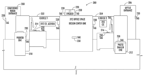
[0079] FIG. 20 shows an office environment 200 in
which various magnetic tags 230 or "stickers" as
mentioned before are located at different areas. The
office environment 200 includes two cubicles 202, 204 as
illustrated, but it should be understood that many
cubicles and offices are located in the office
environment 200. An office entrance 206 is illustrated
on one side and a conference room entrance 208 is
illustrated on the other side. A printer 210 is located
outside cubicle 1 and a photo imager 212 is located
outside cubicle 2. Each cubicle includes a respective
computer 214, 216. A speaker 220 is located on top of
the cubicles. As illustrated, a tag is located at the
office entrance 206 and the conference room entrance 208.
A tag 230 is located on the printer. In one example, the
tag is operative with the processing circuitry in the
printer. A tag 230 is located on the photo imager 212.
In one example, the tag is operative with the photo
imager processing data. A tag 230 is also located at the
cubicle wall between the cubicles 1 and 2. Tags 230 are
located on the speaker 220. A tag 230 is located in each
cubicle 202, 204 and also on each computer 214, 216 and
operative with the processing circuitry. These tags have
CA 02775298 2012-03-23
WO 2011/035413 PCT/CA2010/001477
34
functionality relative to a communications device that
includes the NFC circuit as explained before. For
example, a user enters through the office entrance 206
and certain functions are activated in their
communications device.
[0080] For example, it is possible that the phone
enters a "silent" mode since the user will be in their
cubicle and there is no need for the communications
device to enter a ringing mode. The same occurs if
someone enters the conference room and touches the tag
230 at the conference room entrance with their device.
Also, if someone who does not use the cubicles touches
the tag 230 located at the cubicle space between the two
cubicles, then it gives a location and what type of
office they are walking through such as the Design Center
as illustrated and printed on the cubicle wall. The
speaker 220 is illustrated, in one example, and a user
touches the tag 230 with their communications device and
downloads or uploads music to cause music to be played in
the speaker. The tags 230 in each of the cubicles are
touched to activate a calendar program, for example. If
the tag 230 at a computer is touched, then the computer,
in one example, is operated and starts running a
presentation or the device automatically enters a "remote
control" mode for controlling the computer through the
communications device, such as using Bluetooth or WiFi.
[0081] It is possible by touching the tag 230 in a
cubicle that the user is presented with configuration
options, for example, for operating a coffee maker at
their desk in response to pairing with the coffee maker.
If the tag 230 at the printer 210 is touched, then the
printer 210, in an example, is instructed to print a
CA 02775298 2012-03-23
WO 2011/035413 PCT/CA2010/001477
certain document such as by causing a Bluetooth or WiFi
connection between the device and printer. If the photo
imager tag 230 is touched, the photo imager 212 could
receive photos from the communications device and begin
5 printing photographs. These are only non-limiting
examples of how the tags 230 are used to establish
functions, such as activating the NFC circuit, and
exchanging protocol information or other data and causing
the device to enter a Bluetooth, WiFi, silent or other
10 device function.
[0082] It should be understood in one example that the
shape on the device and the shape of the sticker or tag
230 are configured similarly and the magnet touched in an
appropriate location to facilitate functionality. Other
15 functions are possible such as an address book exchange
based on device-to-device pairing when one device is in
the instant manager application. The scheduling of a
meeting in another example is proposed in response to a
device-to-device pairing when in the calendar application
20 or when entering the conference room. Meeting schedules
and calendar applications are brought up automatically to
discuss at a meeting. Other possibilities include the
user with options to open a car door and start a car in
response to pairing with a vehicle if a tag is located on
25 a vehicle, or automatically present the user with options
to control and/or use a personal video recorder (PVR) in
response to connection with a personal video recorder.
This is an IP based connection over WiFi from a remote
location in one example. The device, in another example,
30 also acts as a passive accessory such as paying a subway
toll when entering the subway or receiving a virtual
receipt when checking out at a store.
CA 02775298 2012-03-23
WO 2011/035413 PCT/CA2010/001477
36
[0083] The location mode, in one example, applies to
the office environment in FIG. 20. When a user passes
through the cubicle area and touches the tag 230 on the
space between cubicles 1 and 2, this NFC enabled tag
gives a location and the type of office. Thus, the
system and device triggers an action when a user is
"detected" as being in proximity to a location of
contextual importance. For example, a user who has been
detected may already be in the correct location for a
meeting, which may be in that user's corporate calendar
application. The user does not receive a warning
indicator, since they know they are already supposed to
be in the meeting. There may be some "implicit"
detectability by a user noticing improved
usability/behaviors of the mobile device. This overcomes
the disadvantages when wireless devices typically behave
in the same manner regardless of context or geographical
location. For example, a calendar event such as a
meeting reminder may be triggered even though the user is
already physically in the meeting.
[0084] Common devices in an office, such as a
telephone or computer, are tagged as shown in FIG. 20 or
otherwise identified on the device so that the device
"knows" when the user is in the office. This could be
used to change the behavior of the device or other
devices in the office. For example, if the user's device
has a 9:00 a.m. calendar item "meet with colleague" and
the meeting is in the user's office or cubicle, then the
user's device may communicate with the user's desk phone
to turn off the ringer during the meeting. The device
could also be pre-tagged to activate other devices such
as a punch clock when the user is nearby. Wireless
CA 02775298 2012-03-23
WO 2011/035413 PCT/CA2010/001477
37
protocol such as Bluetooth or WiFi may be used.
Geographical and proximity signals such as GPS, magnetic
location and similar functions, may be used to provide
the device with data relating to the location of the
user.
[0085] FIG. 21 illustrates a printer 310 such as used
in the office environment of FIG. 20. The printer
includes a passive magnetic tag 330 of the type described
before. The tag can be stuck on the printer by various
techniques. It includes basic tag functions such as
described relative to the business card holder in FIGS.
9-19 in terms of activating the NFC circuit in the
device. The printer 310 includes a processor 340 and a
Bluetooth or WiFi communications module 350. In this
particular example, the user in cubicle 1 or cubicle 2
can take their communications device 20 such as shown in
FIG. 1 and touch the magnetic tag 330. This enables the
NFC circuit and the NFC communications protocol
established to negotiate and activate a Bluetooth or WiFi
connection in connection with the Bluetooth or WiFi
module 350. The communications device downloads data to
the printer processor 340, allowing a page to be printed.
Alternatively, the tag 330 is connected to the processor
and has stored data that is sent to the processor for
printing or receives data from the communications device
for transfer to the printer. In another example, this
tag 330 is programmable as a passive tag with information
transferred from the communications device 20. This tag
330 also, as noted before in one example, has an
identifier such as an IP address. When the user leaves
the office space and returns and touches the tag again,
CA 02775298 2012-03-23
WO 2011/035413 PCT/CA2010/001477
38
the communications device automatically knows the IP
address and is configured to work with that printer 310.
[0086] The tag is also referred to as a magnetic tag
and a sticker and includes a mounting member 332 as
illustrated. This mounting member 332 could be an
adhesive tape, a Velcro attachment or other adhesive or
magnetic attachment (if the supporting surface is
metallic). There are Type 1, Type 2, Type 3 and Type 4
tags with functionality that in different examples are
implemented. Some tags are read-only as used and others
are read/write. In certain examples, some of the tags
are single-state and are read-only. Tags have memory
capacity in some examples of 96 bytes plus 6-byte OTP
plus 2 bytes metal ROM. Others are 48 bytes and some are
1 Kbyte and others variable. Other examples of tags are
lockable to read-only and some include security for a 16
or 32-byte digital signature in another example. A
magnet 334 is illustrated and configured to activate the
NFC circuit in a communications device when placed in the
"kiss" configuration with each other. The data store 336
is illustrated. The housing 338 supports the magnet 334
and carries the magnet. The magnet is configured to be
magnetically sensed by a magnetic sensor carried by the
communications device to activate the NFC circuit within
the communications device and communicate using an NFC
communications protocol. The data store 336 stores data
regarding a function of the communications device to be
magnetically coupled by the magnet. The data store is
configured to be read by the communications device using
an NFC communications protocol after the NFC circuit had
been activated. The tag is mounted within the workspace
to interact based on instructions stored within the data
CA 02775298 2012-03-23
WO 2011/035413 PCT/CA2010/001477
39
store regarding the function of the communications
device. The data store 336 could be formed as ROM or
other storage as known and engage with other circuitry or
other programmable devices in some examples. The magnet
can be positioned and configured at different locations
to engage the magnetic sensor on a communications device
and operate to activate the NFC circuit in the
communications device such that data in the data store
can be read and used by the communications device.
[0087] The tag or sticker, in one example, is formed
as a shape that is recognizable by the communications
device. For example, the tag is formed as a geometric
shape with the magnet configured or positioned at a
predetermined location on the tag or sticker based on the
geometric shape. The communications device has its
magnetic sensor oriented such that the magnet on the tag
or sticker aligns with the magnetic sensor on the
communications device. The tag or sticker is configured
such that the communications device is positioned against
the tag or sticker in a certain orientation to enable the
NFC circuit. In another example, reference marks are
included on both the tag or sticker and the
communications device such that the communications device
is aligned with the tag or sticker using the reference
marks in order to enable the NFC circuit. In FIG. 21, a
reference mark is shown at reference 339. In this
example, the reference mark 339 is formed as a small
protrusion.
[0088] FIG. 22 illustrates another embodiment and
showing communication devices 420, 430 that use a
magnetic sensor 426, such as a Hall Effect sensor, and
operate in conjunction with an electromagnet 424 instead
CA 02775298 2012-03-23
WO 2011/035413 PCT/CA2010/001477
of a permanent magnet. Other details are illustrated
such as the housing 430, keyboard 432, and display 434.
The electromagnet 424 and sensor 426 are located at the
top 436 of the devices in this example. The electromagnet
5 that is used is illustrated, for example, in FIG. 8 as
the electromagnet shown at reference numeral 135. This
electromagnet 424 transmits pulses of energy as
communication signals. This limited data can be enough
communications data to the other device to receive
10 through its sensor 426, such as the Hall Effect sensor,
and activate a Bluetooth connection, thus not requiring
activation of any NFC circuit. A spacing should be made
sufficient between the sensor, such as the Hall Effect
sensor, and the electromagnet 424 in one device because
15 the energy from the electromagnet could be received
inadvertently by the sensor 426 on the same device 420
instead of the other device 422. The amount of energy
used by the electromagnets is sufficient to allow pulses
to be transmitted to the sensor 426 in a kiss gesture,
20 but not enough energy to activate the sensor on the same
device on which this electromagnet is positioned. The
spacing and distance, naturally, depends on the amount of
energy in the pulses that are transmitted from the
electromagnet.
25 [0089] FIG. 23 is a perspective view of a
communications device 500 and showing a top end cap
removed and the magnetic sensor 502, magnet 504 and a
mini Near Field Communications (NFC) antenna 508 mounted
at the top of the device. A hall integrated circuit (IC)
30 is located at this top section (not shown). The NFC
controller integrated circuit (IC) is also in this
general area (not shown). It is possible to form these
CA 02775298 2012-03-23
WO 2011/035413 PCT/CA2010/001477
41
different components to be replaced as one unit. An end
cap covers the top of the communications device and can
be removed and the components removed as one circuit unit
to facilitate replacement.
[0090] FIG. 24 shows a communications device 500
seamlessly connected with a projector 520 or other
peripheral as a user travels, giving presentations from
the device 500 to research partners, conferences and
executive meetings. A tag 530 as described before is
installed on pre-existing hardware, such as a projector
as illustrated, and simplifies the connection between a
personal computer and projector or gives direction to the
communications device. The tag 530 is located near the
rear of the projector in this example. In one example,
accessories such as headsets are pre-installed with
identification tags allowing Bluetooth pairing using the
kiss gesture with the device. The tags in another
example are installed on printers such as described
herein above and store the network path providing
relevant data necessary for printing from the
communications device through an available WiFi network.
In the illustration of FIG. 24, the user scans the
projector tag 530 mid-conversation, never having to
devote his attention to launching the Near Field
Communications from the communications device.
[0091] Similar examples are accomplished with a tag
530 embedded in a car stereo at the manufacturer or a
third party Bluetooth car kit that is a tag with pre-
programmed conductivity data. A tag is added to an
existing Bluetooth stereo and writes the conductivity
data to the tag using the communications device 500 in a
kiss gesture. For example, in the speaker 220 (FIG. 20),
CA 02775298 2012-03-23
WO 2011/035413 PCT/CA2010/001477
42
it is possible to write conductivity data to its tag
using the communications device. This gives a user
control over connecting and disconnecting to a car
system. In some cases, automatic conductivity is not
desired. The Bluetooth does not have to be active on the
communications device. The act of scanning the tag in a
kiss gesture launches the Bluetooth and establishes the
connection. The kiss tag, in one example, is scanned to
change user profiles, connect a media player through the
stereo speakers, and achieve active hands-free phone
functionality.
[0092] FIG. 25 shows a communications device 500
connected initially with the kiss gesture to the tag 532
at a subway station where the tag 532 is attached to a
subway terminal 540 to link the user to scheduled arrival
and departure time information. The tag, in another
example, is used at bus terminals. Where no data plan is
required, entire schedules are stored on the tag's
on-board memory. It is possible to grab updated train
schedules with a single gesture as a user walks through a
busy subway. This is similar to the advantage in which
action is performed without looking at the device and
there is no requirement to look through software menus to
activate NFC when driving down the road in the automobile
example described above.
[0093] FIG. 26 shows a communications device 500
connected in communication to a personal computer 550 in
which the user automatically adjusts his communications
device to separate his professional life from his
personal life and leisure activities. Other examples
abound. The tags 534 are installed at work or in the
office and are quickly scanned to notify the
CA 02775298 2012-03-23
WO 2011/035413 PCT/CA2010/001477
43
communications device 500 that a user has entered the
work environment. Ringer profiles are automatically
switched and calendar events changed. Arriving at home,
tags are installed at the entrance or as part of a
docking bay to let the communications device 500 know
that the user is back at home and adjusts settings
accordingly. The calendar events for home and leisure
activities take priority leaving work back at the office.
Additionally, a tag in one example is placed in a car and
automatically initiates Bluetooth conductivity with the
stereo and enters a hands-free driving mode. Again, the
kiss gesture with the communications device 500
eliminates the requirement to sift through menus every
time the user moves, making location awareness and
convenience not a hassle.
[0094] FIG. 27 shows a media centric alternative in
which a user has Bluetooth pairing and groups to access
media. For example, a father uses his or his son's
communications device 500 and engages in multi-player
gaming via a communications connection. It is possible
to stay up-to-date with popular culture and media by
scanning a tag 536 on an upcoming movie poster while
waiting at an airport. The device 500 instantly launches
into a website providing show times, reviews, and local
ticket sales. Tickets are ordered directly from the
device to share the event with the son via other groups.
Thus, a user seamlessly grabs data.
[0095] FIG. 28 shows a timing diagram with relative
time with time as TO, Ti, T2, T3, T4 and T5 for
activities that occur during the kiss gesture followed by
activating NFC and magnetic detection and Bluetooth. The
CA 02775298 2012-03-23
WO 2011/035413 PCT/CA2010/001477
44
Bluetooth connection has no ending shown because it will
end when the communications session ends.
[0096] FIG. 29 illustrates another embodiment showing
a communications device 620 that transfers contact
information such as with a compatible business cardholder
650 and can operate as a passive device, in this example,
similar to a passive magnetic tag (or passive NFC tag) as
described before. It can operate actively also as
described. Instead of using magnetic detection as
illustrated in the embodiment relative to FIGS. 9-19,
however, an accelerometer 621 as a vibration sensor is
used such as the type explained with regard to the
accelerometer 137 in FIG. 8. The business cardholder 650
as illustrated includes an interface 652 for contacting
the device 620 at the rear and a hinged cover 654 and
data entry point 656 where business cards can be scanned
or information entered on a keypad as non-limiting
examples. A processor circuit 657 provides general
functions for operation of the business cardholder and
its associated function, for example, NFC circuits, scan
circuits or keyboards. An NFC tag 660 of the type as
explained before is included. The communications device
620 includes similar components as explained relative to
previous figures such as the housing 630, keypad 632, and
display 634.
[0097] The accelerometer 621 implements NFC automatic
tag detection (and automatic peer-to-peer detection).
The accelerometer 621 recognizes the tapping of a device
against the tag 660 of the cardholder 650 or similar
passive device, i.e., recognizes the vibrations.
Instead of using the Hall effect sensors and magnets to
wake up the NFC circuit, the circuit uses tap recognition
CA 02775298 2012-03-23
WO 2011/035413 PCT/CA2010/001477
as a vibration sensor and accelerometer in this example.
It should be understood that when the device is tapped
against another object, for example, the NFC tag 660, a
profile is generated as a matter of certain accelerometer
5 parameters being met or exceeded. If the profile is
compared against a known tap profile, it will wake the
NFC circuit and initiate communication.
[0098] As noted before, the communications device 620
includes the accelerometer 621. The accelerometer 621
10 could be formed as a sensor based upon piezoelectric
elements. The accelerometer 621 in one example includes
a microelectomechanical system (MEMS), such as a
capacitive accelerometer. Other accelerometers, including
piezoelectric, piezoresistive and gas-based
15 accelerometers, are used. By way of example, in one
embodiment the accelerometer is a LIS3L02AQ tri-axis
analog accelerometer from STMicroelectronics of Geneva,
Switzerland. In some embodiments, a single integrated
device is used, for example the LIS3L02DQ tri-axis
20 accelerometer with I2C or SPI interface from
STMicroelectronics. The selection of an appropriate
accelerometer as a vibration sensor, in one example, is
based upon the frequency response range and the
sensitivity response of the communications device during
25 tapping.
[0099] A dual axis accelerometer is used in one
example and outputs an x-axis signal and a y-axis signal.
A tri-axis device, in one example, outputs signals for
orthogonal x-, y-, and z-axes. The output signals are
30 analog voltages proportional to accelerative force in the
axis direction. For example, at least one tri-axis
accelerometer outputs a voltage that corresponds to a
CA 02775298 2012-03-23
WO 2011/035413
PCT/CA2010/001477
46
range of positive and negative linear accelerations of
1.7g. The accelerometer in an example embodiment
includes various filters, signal conditioners, etc., for
conditioning the output signals.
[00100] Many modifications and other embodiments of the
invention will come to the mind of one skilled in the art
having the benefit of the teachings presented in the
foregoing descriptions and the associated drawings.
Therefore, it is understood that the invention is not to
be limited to the specific embodiments disclosed, and
that modifications and embodiments are intended to be
included within the scope of the appended claims.