Note: Descriptions are shown in the official language in which they were submitted.
I I
CA 02775507 2012-04-30
BRG 10 1099 cs08
Merchandise Feed Insert for a Merchandise Feed System
Description
The invention relates to a merchandise feed insert for a merchandise feed
system (Claim 8)
for automatic conveyance of merchandise located along the merchandise feed
insert in one transport
direction B to one visible edge of a shelf equipped with the merchandise feed
system as claimed in
Claim 1.
Both in retail and wholesale businesses such as for example drugstores,
grocery stores,
discount stores, toy stores and the like, shelves are required for storing and
displaying products.
When products are displayed and also stored it is desirable for the respective
product to be as much
as possible aligned with the adjacent products on the shelf bottoms on the
front so that the product
is easily visible and accessible to the consumer and the arrangement of
products is aesthetically
pleasing. In order to implement this arrangement of products, known systems
encompass the use of
a pushing system to push the respective products or the row of products in the
direction of the front
of the shelf when the frontmost product is removed or the products are
restocked.
There can be divider plates for separating adjacent rows of products.
Such a merchandise feed system is shown for example in WO 2009/097655 Al which
[consists] of a plurality of merchandise feed inserts consisting of an inner
housing which holds rolls
and an outer housing which holds the inner housing and two end caps which can
be slipped onto the
outer housing front and back and which are applied to a carrier according to
Figure 7 in a suitable
arrangement, The merchandise feed takes place by tilting, therefore without
the expenditure of
mechanical or electrical force/energy use, specifically solely by the weight.
CA 02775507 2012-04-30
The object of this invention is to provide a more easily mountable merchandise
feed insert
which can be produced more cheaply.
This object is achieved with the features of Claims I and S. Advantageous
developments of
the invention are given in the dependent claims and all combinations of at
least two of the features
given in the specification, the claims and/or the figures also fall within the
framework of the
invention.
The basic idea of this invention is, instead of an outer housing for fixing
the transport rolls
on a roll carrier, to provide two profile rails which are produced especially
from plastic, preferably
as a plastic profile, and which can be clipped independently of one another
onto the opposite sides
of the roll carrier. In this invention it is especially advantageous that the
merchandise feed insert can
be produced from a uniform material.
On the one hand a different width of the merchandise feed insert can be
implemented by the
configuration as claimed in the invention on the one hand with the same
profile rail so that the
merchandise feed insert as claimed in the invention can be used more flexibly.
On the other hand,
less different material is needed for fixing of the transport roll on the roll
carrier. The profile rails as
claimed in the invention moreover have a lower weight than comparable profile
rails with transport
rolls according to the prior art. This also reduces material costs.
By a first and/or second fixing section which is located on opposite ends of
the roll carrier
being made integrally with the roll carrier for bringing the merchandise feed
insert to the shelf
according to one embodiment of the invention, the production of the
merchandise feed insert is
greatly simplified and becomes even more economical.
According to another embodiment of the invention it is provided that the
profile rails are
2
I I
CA 02775507 2012-04-30
made as a U-profile and to hold the roll carrier in the U-profile, catch means
being arranged on
inside walls of the profile rails. In' this way a connection as simple but
effective as possible between
the profile rails and the fixing section is achieved so that the roll carrier
and the transport rolls are
reliably held in their operating position.
In another advantageous embodiment of the invention it is provided that the
catch means
each consists of an upper catch projection and an opposite lower catch
projection as well as
corresponding snap-in elements. This measure further simplifies the
merchandise feed insert as
claimed in the invention in the number of parts and in this way the mounting
of the merchandise
feed insert is also simplified so that the production costs are reduced.
To the extent the upper catch projections are located on an upper leg of the
profile rails, the
mounting of the merchandise feed insert as claimed in the invention is further
simplified.
In another advantageous embodiment of the invention it is provided that the
upper snap-in
elements corresponding to the upper catch projections are provided at least
partially on, especially
upper ends of, webs of transport roll holders for supporting the transport
rolls. This measure further
reduces the number of functional elements and greatly simplifies installation.
In particular, holding by clamping in combination with the deformation of the
profile rails
results in especially simple installation since no additional aids are
necessary and the profile rails
provide for fixing of the transport rolls in the roll carrier independently of
one another.
Advantageously it is furthermore provided that the lower catch projections
each have a
bevel pointed toward the roll carrier for simpler installation, especially
without aids.
According to another preferred embodiment of the invention it is provided that
the profile
rails are made flush in the first and/or second fixing section. In this way
the profile rails have a
3
I i
CA 02775507 2012-04-30
plane lateral outside contour and can be easily stacked, transported and
installed.
The invention furthermore relates to a merchandise feed system with at least
one
merchandise feed insert which is tilted to one visible edge of a merchandise
feed insert in the
merchandise feed system according to one of the preceding claims. The
aforementioned advantages,
features and embodiments also apply to the merchandise feed system as claimed
in the invention.
Other advantages, features and details of the invention will become apparent
from the
following description of preferred exemplary embodiments and using the
drawings.
Figure 1 shows a perspective view of one embodiment of a merchandise feed
insert as
claimed in the invention in the installed state and
Figure 2 shows a perspective exploded representation of one merchandise feed
insert
according to Figure 1.
The same or equivalent components are identified with the same reference
numbers in the
figures.
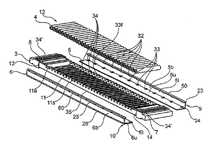
Figure i shows a disassembled merchandise feed insert I as is used- for
example on a shelf
bottom as described according to Figure 7 from WO 2009/097655.
Depending on the size of the merchandise to be conveyed by one or more
merchandise feed
inserts I to one visible edge 2 in one transport direction B, different or
several of the merchandise
feed inserts I can be used. They can moreover be supported by dividers so that
neater guidance of
the products located on the shelves, separated for example according to
merchandise groups, is
easily enabled.
The merchandise feed insert I comprises a roll carrier 3 for accommodating a
set of
transport rolls 4 which are supported in the roll carrier 3 in corresponding
transport roll receivers
4
CA 02775507 2012-04-30
11.
The transport rolls 4 are located transversely to the transport direction B
and both the roll
carrier 3 and also the transport rolls 4 are advantageously formed from
plastic in order on the one
hand to enable low-friction and on the other easy conveyance. Moreover the
production of the roll
carrier 3 and the transport rolls 4 from plastic is economically possible.
The transport rolls 4 form a roll path 12 and due to the slanted arrangement
of the
merchandise feed insert 1 on the carrier, products which have been placed on
the roll path 12 are
automatically transported to the visible edge 2. No force need be expended for
this purpose.
The transport rolls 4 consist of a cylindrical transport section 4f with a
constant diameter D
and with bearing pins 4s which are molded onto the opposite ends 4e with a
diameter d for
engaging opposite transport roll receivers 11. Laterally in and opposite the
transport direction B
there are webs 1I Is for limiting the motion of the transport rolls 4 whose
upper end Ile ends
roughly flush with the bearing pins 4s.
So that the transport rolls 4 are secured in the transport roll receivers 11,
profile rails 5, 6
with a U-profile can be clipped laterally on the roll carrier 3 such that the
transport rolls 4 are fixed
in the respective transport roll receiver 1 I such that the transport rolls 4
rotate freely, but cannot
spring out of their transport roll receiver 11. The profile rails 5, 6 are
advantageously made as
plastic profile.
The roll carrier 3 on the two ends of the roll path 12 which are opposite in
the transport
direction B each has one fixing section 7, 8 which are made especially
axisymmetrically to the roll
path and are molded in one piece on the roll carrier 3.
For mounting purposes the profile rails 5, 6 are clipped transversely to the
transport
CA 02775507 2012-04-30
direction B onto the roll carrier 3, the profile rails 5, 6 adjoining flush
the stops 13, 14 of fixing
sections 7,8 which are aligned opposite one another. The profile rails 5, 6
are each flush with the
sides of the fixing sections 7, 8.
The profile rails 5, 6 have several upper catch projections 32 located on one
inner wall 5i, 6i
of the U-shaped profile of the profile rails 5, 6 as well as lower catch
projections 33 located
opposite them in the U-shaped profile as catch means. They can be snapped into
corresponding
upper and lower snap-in elements 34, 35 (catch means) which are arranged
distributed along the
sides of the roll carrier 3. In the illustrated embodiment there are twelve
upper and twelve lower
catch projections 32, 33 on each profile rail 5, 6 and twelve upper and lower
snap-in elements 34,
35 on the two opposite sides of the roll carrier 3.
The upper catch projections 32 are each molded on the short upper leg So, 6o
of the profile
rails 5, 6 while the lower catch projections 33 are molded on the long outer
leg 5u, 6u of the profile
rails 5, 6. The bottoms 5b, 6b each connect the two legs So, 6o, Sz, 6u.
The upper snap-in elements 34 are provided mainly (except for the front and
back upper
snap-in elements 34') on the upper ends I Ie of the webs I I s as offsets
which point to the roll path
12 and behind which the upper catch projections 32 extend. Here it is
advantageous to form only
each n-th (here: each third) of the webs I Is, especially at least every other
one, as catch means.
Mounting takes place by slanted seating of the upper catch projections 32 of
the profile rails
5, 6 on the respective upper snap-in elements 34. Then the profile rails 5, 6
with the catch
projections 32 snapped in are rotated such that the lower catch projections 33
which are provided
with bevels 33f lock over the lower snap-in elements 35 in the form of a
continuous offset. The
lower legs Su, 6u of the U-profiles are made longer and are used as levers so
that the profile rails 5,
6
i i
CA 02775507 2012-04-30
6 can be detached again by lifting the lower legs 5u, 6u.
For this purposes the lower catch projections 33 must be lifted over the lower
snap-in
elements 35.
The bottom 5b of the profile rail 5 at the same time forms profiling 9 on the
side opposite
the U-profile for accommodating the roll carrier 3, the profiling 9 in the
illustrated embodiment
having two side cheeks 23,24 which are flush with the legs So, 6o, 5u, 6u.
The bottom 6b of the profile rail 6 forms profiling 10 which corresponds to
the profiling 9
by the bottom 6b coming into contact with the bottom 5b' of a corresponding
merchandise feed
insert 1'. The profiling 10 in this respect has recesses 25, 26 which
correspond to the side cheeks 23,
24, here in the form of offsets. The profilings 9 and 10 are made as tongue
and groove connection
in this exemplary embodiment.
Except for the profilings 9, 10, the profile rails 5, 6 are made symmetrically
to one another.
Based on the configuration as independent profile rails 5, 6, the roll carrier
3 and the roll path 12
can have different widths.
The first and second fixing sections 7, 8 have a plurality of divider holders
27, 28 which are
arranged flush to one another and transversely to the transport direction B
along the first and second
fixing sections 7, S. Corresponding divider holders 27,28 are provided with
corresponding
identifications for easier assignment of the divider holders 27, 28 which
correspond at the time.
7
CA 02775507 2012-04-30
Reference number list
B transport direction
1 merchandise feed insert
2 visible edge
3 roll carrier
4 transport rolls
profile rail
5b bottom
50 upper leg
5u lower leg
5i inside wall
6 profile rail
6b bottom
6o upper leg
6u lower leg
6i inner wall
7 first fixing section
8 second fixing section
9 profiling
profiling
i l transport roll receiver
f i e upper ends
8
CA 02775507 2012-04-30
u s webs
12 roll path
13 stops
14 stops
23, 24 side cheeks
25, 26 recesses
27, 28 divider holders
32 upper catch projections
33 lower catch projections
33f bevels
34 upper snap-in elements
35 lower snap-in elements
9