Note: Descriptions are shown in the official language in which they were submitted.
CA 02775580 2017-01-05
MEDICAL ULTRASOUND DEVICE WITH LIQUID DISPENSING
DEVICE COUPLED TO A THERAPY HEAD
[0001]
BACKGROUND
[0002] High intensity focused ultrasound (HIFU) has gained increased
popularity and support
as a therapy device in the medical community. Ultrasound energy has been used
extensively in
non-therapeutic procedures such as tissue imaging for diagnostic purposes.
HIFU involves higher
levels of power (over diagnostic ultrasound), to achieve a variety of physical
effects in tissue for
the purpose of achieving a desired therapeutic effect. A recurring design
issue for HIFU
treatment devices is balancing the needs of the therapeutic demands a
procedure may require,
and the acceptability of the device produced by medical device manufacturers.
This is
particularly true in aesthetic medicine, where devices of therapeutic utility
must meet the
rigorous utility, image and usability demands of practitioners of aesthetic
medicine and their
clientele.
1
CA 02775580 2012-03-26
WO 2011/041239 PCT/US2010/050280
BRIEF SUMMARY
[0003] The present invention provides a medical high intensity focused
ultrasound system
comprising a base unit and a therapy head. The base unit includes a primary
digital controller
having a primary interface, a cooling liquid recirculation circuit, and a
cable carrying electrical
and information transmission members and cooling liquid conduits. The therapy
head includes a
body which is coupled to the cable, a secondary controller on the body having
a secondary
digital interface, where the secondary controller is coupled to the primary
controller by the
electrical and information transmission members in the cable. The therapy head
further includes
a cartridge removably attachable to the body which includes a sealed enclosure
filled with an
acoustic coupling liquid and a high intensity focused ultrasound transducer
therein. The
cartridge is coupled to the cooling recirculation circuit by way of the
cooling liquid conduits in
the cable when the cartridge is attached to the body.
[0004] The cable may be flexible and the system does not require use of a
separate support arm
as with many prior art systems (although it does not exclude the use of a
separate support arm).
The user can rely on the secondary digital interface in order to control the
central aspects of the
system and cooling can be provided via the same cable which provides the
electrical
connections. The cartridge is removable and disposable, allowing easy
replacement of the
transducer by attaching a new cartridge having a sealed enclosure where all
electrical and
cooling connections can be easily re-established with the body of the therapy
head.
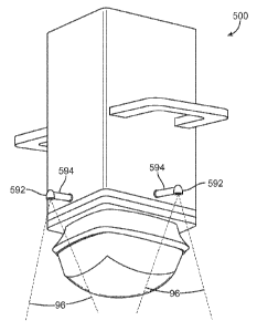
[0005] These systems may further comprise a liquid dispersion device on the
therapy head
which allows the user to apply a coupling liquid to the patient in order to
assure adequate
acoustic coupling between the therapy head and the patient's posterior skin.
In specific
embodiments, the liquid dispersion device may deliver a volume of the acoustic
coupling liquid
from the sealed enclosure. In other embodiments, the liquid dispersion device
may deliver a
volume of the cooling liquid from the therapy head. Optionally, the system may
comprise a
plurality of liquid dispersion devices connected with the liquid recirculation
system, in which
case a flow control subsystem will typically control the liquid flow from the
circulation system
through the dispersion devices.
2
CA 02775580 2012-03-26
WO 2011/041239 PCT/US2010/050280
[0006] In specific aspects, the liquid circulation circuit may comprise a
chiller to provide for
heat exchange with the therapy head. In other specific aspects, the cable may
carry from 12 to
24 coaxial cables for connection to the secondary digital interface and to the
ultrasound
transducer. The ultrasound transducer may comprise a short stack transducer
assembly, and the
primary and secondary digital interfaces may comprise a serialize and
deserialize device
(SERDES devices).
[0007] In other aspects of the invention, methods are provided for modifying a
patient with an
ultrasonic therapy head, where a coupling liquid is applied to a region of the
patient's skin using
a liquid dispensing device mounted on a therapy head. The therapy head is
pressed into contact
with the skin region to be treated, and a transducer within a cartridge
attached to the therapy head
modifies the tissue.
[0008] In still another aspect of the present invention, electronic
communication is provided
between a computer controller and a base unit and a therapy head using a
reduced physical wire
cable. A serializing device sends control commands, queries and data in
serially presented
packets through a single wire. A deserializing device deserializes the control
commands, queries
and data in a receiving interface, wherein the serializing and de-serializing
interfaces using the
same protocol to pack and unpack the electronic information sent over the
wire.
3
CA 02775580 2012-03-26
WO 2011/041239 PCT/US2010/050280
BRIEF DESCRIPTION OF THE DRAWINGS
[0009] Fig. 1 shows a medical ultrasound system of the prior art;
[0010] Fig. 2 is a perspective view of a medical ultrasound system in
accordance with an
embodiment;
[0011] Fig. 3 is a perspective view of a medical ultrasound system in
accordance with an
embodiment;
[0012] Fig. 4 is a front view of the base unit from Fig. 2;
[0013] Fig. 5 is a side view of the base unit from Fig. 2;
[0014] Fig. 6 is a interior perspective view of the main compartment according
to an
embodiment;
[0015] Fig. 7 is a interior profile view of the main compartment according to
an embodiment;
[0016] Fig. 8 is a perspective view of the main compartment with cover
according to an
embodiment;
[0017] Fig. 9 shows a cross-section of a system for separating gas from a gas-
containing liquid
in accordance with an embodiment.
[0018] Fig. 10A illustrates the operation of the degassing system of Fig. 9.
[0019] Fig. 10B illustrates an alternative embodiment of a degas system.
[0020] Fig. 11 is a schematic diagram illustrating a system for separating gas
from a gas-
containing liquid in accordance with another embodiment.
[0021] Fig. 12 is a block diagram of a medical ultrasound system having a
degassing unit in
accordance with an embodiment.
[0022] Fig. 13 is a cross section of a cable according to an embodiment;
[0023] Fig. 14 is a perspective view of the treatment head according to an
embodiment;
[0024] Fig. 15 is a perspective view of the treatment head according to an
embodiment;
4
CA 02775580 2012-03-26
WO 2011/041239 PCT/US2010/050280
[0025] Fig. 16 is a transparent profile view with internal components of the
treatment head
according to an embodiment;
[0026] Fig. 17 is a transparent perspective view of Fig. 16;
[0027] Fig. 18 is a bottom isometric view of the therapy head of Fig. 15;
[0028] Fig. 19 is a schematic diagram representing some components of a
medical ultrasound
system in accordance with an embodiment;
[0029] Fig. 20 is a schematic diagram representing some components of a
medical ultrasound
system in accordance with an embodiment;
[0030] Fig. 21 is a perspective view of a lower compartment, or cartridge, for
the therapy head
of Fig. 16 in accordance with an embodiment;
[0031] Fig. 22 is an exploded perspective view of the lower compartment of
Fig. 21;
[0032] Fig. 23 an exploded perspective view of a thermoelectric device stack
and related
components for the therapy head of Fig. 22;
[0033] Fig. 24 is a perspective view of the upper and lower compartment
thermoelectric device
stacks;
[0034] Fig. 25 is a perspective view of the combined thermoelectric device
stack;
[0035] Fig. 26 is a perspective view of the exploded components of Fig. 21;
[0036] Fig 27A is a schematic diagram representing components of a medical
ultrasound
system in accordance with another embodiment;
[0037] Fig. 27B is an isometric view of the bottom of the upper section in
accordance with an
embodiment.
[0038] Fig. 28 is an isometric view of a transducer cartridge for a therapy
head in accordance
with an embodiment;
[0039] Fig. 29A is an exploded isometric view of the transducer cartridge of
Fig. 28;
CA 02775580 2012-03-26
WO 2011/041239 PCT/US2010/050280
[0040] Fig. 29B is an isometric view of a bottom portion of a transducer
cartridge displaying
an alternative fluid conduit in accordance with an embodiment;
[0041] Fig. 30 is an exploded isometric view of the transducer cartridge
having a thermal
regulating device according to an embodiment;
[0042] Fig. 31 is an exploded isometric view of the transducer cartridge
according to an
embodiment;
[0043] Figs. 32A-B provide a pressure relief mechanism in accordance with an
embodiment
for the cartridge;
[0044] Figs 33A-B provide a pressure relief mechanism in accordance with an
embodiment for
the cartridge;
[0045] Fig. 34 illustrates the vacuum assembly of Fig. 9;
[0046] Fig. 35 shows an alternative embodiment of an interface cable;
[0047] Fig. 36A shows a tall stack transducer assembly;
[0048] Figs. 36B-D provide views of a short stack transducer assembly,
according to
embodiments.
[0049] Fig. 37 shows a unigrip handle according to an embodiment.
[0050] Fig. 38 is a block diagram of a coupling fluid system, in accordance
with an
embodiment.
[0051] Fig. 39 shows a medical ultrasound system having a coupling fluid
reservoir and a
coupling fluid line, in accordance with an embodiment.
[0052] Fig. 40 is a block diagram of fluid flow system, in accordance with an
embodiment.
[0053] Fig. 41 is a transparent side view of a treatment head having a spray
nozzle according
to an embodiment.
[0054] Fig. 42 is a perspective view of an ultrasound head having handles and
spray nozzles
coupled with the handles, in accordance with an embodiment.
6
CA 02775580 2012-03-26
WO 2011/041239 PCT/US2010/050280
[0055] Fig. 43 is a perspective view of an ultrasound head having offset spray
nozzles, in
accordance with an embodiment.
[0056] Fig. 44A is a perspective view of an ultrasound head having integrated
spray nozzles, in
accordance with an embodiment.
[0057] Fig. 44B provides a view of an ultrasound therapy head having a guide
component for
the liquid dispersal device(s) according to an embodiment;
[0058] Fig. 45 is an illustration of a template for use in creating a variable
size and alignment
pattern on a patient body according to an embodiment.
[0059] Fig. 46 is an illustration of the use of a variable treatment size
pattern in an
embodiment.
[0060] Fig. 47 is an illustration of the use of a variable treatment alignment
pattern according
to an embodiment.
[0061] Fig. 48 illustrates a simplified block diagram of a computer system in
accordance with
embodiments.
[0062] Fig. 49 schematically illustrates a series of modules according to an
embodiment.
[0063] Fig. 50 is an example of a touch screen.
[0064] Fig. 51 shows steps for providing treatment information to a control
module in
accordance with embodiments.
[0065] Fig. 52 illustrates a module for providing variable treatment to
different areas in
accordance with embodiments.
[0066] Fig. 53 shows an arrangement of broadcast zones divided into treatment
and non-
treatment zones.
[0067] Fig. 54 shows steps for establishing a partial treatment area in
accordance with
embodiments.
[0068] Fig. 55 shows a method for partial site treatment in accordance with
embodiments.
7
CA 02775580 2012-03-26
WO 2011/041239
PCT/US2010/050280
[0069] Fig. 56 shows a method for providing selective treatment at a site in
accordance with
embodiments.
[0070] Fig. 57 shows another method of selective treatment at a therapy head
site in
accordance with embodiments.
8
CA 02775580 2012-03-26
WO 2011/041239 PCT/US2010/050280
DETAILED DESCRIPTION
[0071] In the following description, various embodiments of the present
invention will be
described. For purposes of explanation, specific configurations and details
are set forth in order
to provide a thorough understanding of the embodiments. However, it will also
be apparent to
one skilled in the art that the present invention may be practiced without the
specific details.
Furthermore, well-known features may be omitted or simplified in order not to
obscure the
embodiment being described.
[0072] Described herein are medical ultrasound systems for body contouring,
components of
medical ultrasound systems, and methods for servicing, updating and using
medical ultrasound
systems.
[0073] Medical ultrasound systems on the invention typically include two main
components
with various subcomponents. The first main component is the base unit. The
base unit
component is usually a mobile piece of equipment designed to rest on the floor
and provide an
enclosed form factor that houses numerous subcomponents of the system. Details
of the sub
components are provided throughout the description. Mainly, the subcomponents
that are either
large or heavy, or more conveniently located away from a patient, are stored
in the system base.
The base unit refers to the larger of the two main components. It may have
castors or wheels and
be referred to herein as a cart. Mobility in the base unit is generally
provided for ease of use, but
in no way should be read as limiting the invention in any way.
[0074] The second main component is the treatment head. The treatment head
component of
medical ultrasound systems of the invention is also described herein in
various embodiments. In
a typical aspect, the treatment head has two sections that are detachable from
each other. When
the two sections are properly assembled in such aspects, the treatment head
operates in
conjunction with the base unit to produce ultrasound energy for medical
purposes. Each section
is often referred to herein as the therapy head body, and the cartridge.
Alternatively the therapy
head body may be the upper compartment while the cartridge is the lower
compartment. The
therapy head (or therapy head body) contains subcomponents that are designed
for long wear and
extended use. The cartridge contains subcomponents that are generally designed
for limited use
before being replaced. The term treatment head and therapy head are sometimes
used
interchangeably and may include the cartridge with the upper compartment. The
cartridge
9
CA 02775580 2012-03-26
WO 2011/041239 PCT/US2010/050280
contains an energy emitter, and in most embodiments, this energy emitter may
be at least one
high intensity focused ultrasound (HIFU) transducer. The cartridge generally
is removable and
has a limited life span.
[0075] The primary purpose of the system is to provide therapeutic ultrasound
for the purposes
of body contouring. This intended use of the system is for non-invasive
therapy. That is, the
present system and its many sub components are designed for use outside a
patient body and
typically does not involve any minimally invasive techniques, surgery, or
tissue imaging other
than what the system is capable of performing by itself. The system can
operate independently of
diagnostic, imaging, or anesthetic equipment that might also be used on a
patient. Systems of the
invention also or alternatively can be used in a non-sterile field.
Sterilization of the many parts
and system surfaces is not typically required between uses, though individual
users may choose
to do so for various reasons. The many embodiments of the invention described
herein provide
for a more usable device for body contouring over those of the prior art.
[0076] An interface cable is typically used to connect the base to the
treatment head. A number
of examples of such cables are described herein.
[0077] The description of the many embodiments of each of the components is
not meant to
imply a strict requirement of one embodiment of one component being tied
solely to another
embodiment of another component. Rather the description of the various
embodiments of each
the base unit, the treatment head and the interface cable should be viewed as
interchangeable.
An embodiment of the base unit may be used with more than one embodiment of
the treatment
head, and vice versa. Some embodiments of either the base or the treatment
head will logically
exclude embodiments of the other component. Those skilled in the art will
realize certain
pairings of base unit and treatment head do not go together, however in
general the various
embodiments of one component are designed to work equally well with the
various embodiments
of the other components. The various embodiments are herein described both in
text, and in
annotated drawing descriptions.
[0078] In an embodiment, the base unit is a base with a low center of gravity
and rests on a
frame with casters. Extending from the base is, e.g., a combined ergonomic
front panel and main
system compartment. The main system compartment can be mounted on the frame
with casters,
and the ergonomic front panel serves as one side of the compartment. The front
panel typically
CA 02775580 2012-03-26
WO 2011/041239 PCT/US2010/050280
extends upward from the base and main compartment. One or two handles are
usually integrated
into the front face so that the handle(s) can be easily reached, and a display
screen is commonly
ergonomically positioned for easy viewing. The front panel typically further
possesses at least
one docking port for removably receiving a treatment head. Additional docking
ports may also
be incorporated into the front panel.
[0079] Extending from the upper end of the front panel typically is a display
screen. The
display may also be a touch screen interface. The display panel or the base
unit may have
speakers for producing audible signals for the user. Inputs for other user
interface devices, such
as a keyboard, mouse or pointer device, may also be provided.
[0080] The main compartment of the base unit contains the bulk of the system
electronics.
These electronics typically include a group of treatment head connectors
(electrical and fluidics)
and a treatment head interface board; a digital data interface; system
electronics including a
therapy processor and a high voltage transmitter; electronic control for a
fluidics system (liquid
circulation system) having chiller/fans, fluid tank, pump and sensors; and a
system power supply.
The fluidics system may also incorporate a degas device for removing dissolved
gasses from the
liquid. Additional electronics may be added via one or more daughter board
adapters located on
any one of the existing boards within the system.
[0081] Systems of the invention should typically utilize liquid in the
fluidics system in a
different manner over the prior art. Instead of filling and draining the
therapy head when
replacing a transducer, many embodiments use a transducer in a sealed
cartridge. The cartridge
may contain about 100 to 200 milliliters (m1) of static liquid coupling fluid,
whereas the prior art
may use about 400-500 ml of liquid routed throughout the base unit and the
therapy head. The
cartridge may be designed for using about 120-160 ml, and in another aspect
the cartridge may
contain 130-150 ml. In addition, embodiments herein utilize a cartridge that
is self contained.
Thus, the coupling liquid remains static in the cartridge, and does not need
to be replaced when
that cartridge is removed from the therapy head. Distinguished from the
coupling liquid is a
cooling liquid in many embodiments. The cooling fluid is circulated through a
heat exchanger
thermally connected to the cartridge. The heat exchanger may be in the
cartridge (integrated
within the cartridge) or part of the therapy head and fashioned to draw heat
away from the
cartridge. Using a separate cooling liquid (from the coupling fluid) allows
the cooling liquid
11
CA 02775580 2012-03-26
WO 2011/041239 PCT/US2010/050280
circulation to move the length of the circulation system more efficiently. The
majority of
embodiments also provide for a treatment head that no longer requires constant
filling and
draining, thus reducing the spillage and fluid loss from the fluidics system.
Advantages of some
embodiments of the systems of the invention also or alternatively include
faster and/or cleaner
replacement of the transducer assembly.
[0082] The description of pressures herein make reference to either "absolute"
pressure, or
"gauge" pressure, both measured in PSI. Absolute pressure is the pressure
measured independent
of atmospheric pressure. It is the "absolute" pressure relative to zero PSI
(pounds per square
inch). The gauge pressure is the pressure above the local atmospheric
pressure. Gauge is the
local atmospheric pressure, plus the pressure read in the system or component
described. The
various pressure readings are usually called out, however unless specified,
pressures relating to
the therapy head are generally GAUGE pressures, and pressures in the fluid
circulation
components in the base are generally ABSOLUTE pressures.
[0083] The use of a separate cooling liquid and circulation system (separated
from the
coupling liquid in the cartridge) may allow the circulation system to pump
smaller volumes of
cooling liquid to cool the cartridge. Typically, the cooling system pumps the
cooling liquid at
about 40 PSI (gauge) in the base unit to achieve a therapy head/cartridge
system pressure of
about 20 PSI (gauge). The cooling system pressure is generally above
atmospheric pressure
through out the system, but may approach atmospheric pressure when returning
from the therapy
head to the fluid reservoir (described herein). In these embodiments, the
lower fluid quantity
required in the therapy head allows for a lower volume of fluid to be pumped,
and may in turn
allow for a pump using less power. It may also be true that a lower fluid flow
rate (volume/sec)
is required to provide the same level of cooling as in prior art systems. This
feature provides
another area of bulk and weight savings allowing the present system to be
substantially smaller
in size and weight compared to the prior art. Furthermore, the fluidics system
in some
embodiments no longer requires a degas unit for removing dissolved gases from
the coupling
liquid as are used in prior art devices that circulate a coupling liquid
around the transducer. This
provides the advantage of allowing the system liquid to contain dissolved
gasses without causing
interference in the transmission of ultrasound energy in the cartridge fluid
from the treatment
head to the patient.
12
CA 02775580 2012-03-26
WO 2011/041239 PCT/US2010/050280
[0084] The system described herein typically makes use of higher levels of
integration in the
functions provided reducing power and electrical signal interconnects between
the various
functions allowing for reduced number of circuit cards and cabling internal to
the system
compared to the prior art system shown in Figure 1.
[0085] The system may have an Ethernet adapter to receive a 10/100/1000
Ethernet line which
may be used to link the system to a service computer or the internet, and
provide software
updates, system diagnostic capabilities, account usage updating and/or
investment recovery
banking of unused pay-per-use units for the treatment head (also known as
"user sites" and
described in co-pending US Patent Application 12/407,212, filed March 19,
2009, and entitled
"Methods and Apparatus for Medical Device Investment Recovery").
[0086] The display screen typically included with the system provides system
information and
operational information to the user. In one aspect, the display has touch
screen capabilities,
allowing the user to use the screen as a control interface for operating the
system, checking
system status, running diagnostics programs, displaying error messages and
system alerts, and/or
providing a user with an interface to check non-active functions related to
system usage, such as
checking the user site bank account. The display screen may incorporate both
button touch
screen functions, and motion sensitivity, similar to screens used in personal
data assistants and
mobile phones. It may also or alternatively provide an on/off switch and/or
house a speaker. In
another aspect, the screen is a conventional LCD device.
[0087] One or more foot switch jacks can also or alternatively are provided
for connecting a
single or multifunction foot switch. The foot switch may optionally be used to
control therapy
activation of the system. Some users prefer hand activated therapy treatment
while others prefer
using a foot switch. Typically, systems of the invention can provide the
option for either method
to be used.
[0088] A system power supply is usually provided in the cart. In one aspect,
the power supply
can run on normal amperage and voltage. For example, in the United States, the
system operates
on a standard 115 volt/15 amp 60Hz line using a grounded plug. In Europe the
system operates
on a European standard 240 volts/ 50 Hz line. Similarly the system uses a
power supply that
converts the power of the local standard into the power requirements the
system needs for proper
operation. A safety sensor or watchdog circuit monitors the AC power input as
well as the DC
13
CA 02775580 2012-03-26
WO 2011/041239 PCT/US2010/050280
output of the supply and provides a cut off in the event the power input or
output is out of safety
specification for the system. In an embodiment, the system operates with as
many components as
possible requiring the same voltage. In another embodiment, the system
utilizes one voltage for
all components. In still another embodiment the system utilizes two voltages
for all components.
[0089] The system may have one or more treatment heads connected to the base
unit. The
treatment head(s) are usually connected to the base unit by a cable. In one
aspect, the system has
been partitioned to allow for an interface cable to be used, which combines
electrical and fluid
channels between the base unit and the treatment head. The treatment head may
also or
alternatively possess any of the following: user controls allowing for the
turning on or off of the
transducer, a display to provide status information, a speaker or sound
emitting component or
device, and/or any other controls and indicator lights as may be desired. In
addition to controls
on the treatment head, display, and/or foot switch, the base unit can have
inputs for other user
input devices like a keyboard, mouse (computer pointer device), or other
control unit. A wireless
control device may also be used.
[0090] In one aspect, the treatment head is connected to the base unit using
only the minimum
number of connections required for system operation. The proper functional
partitioning of the
system can allow for a reduction in wires used to connect between the system
electronics in the
base, and the treatment head. A technical challenge in the prior art was the
requirement for
multiple signals wires to be used for the interface between the treatment head
and system. By
proper partitioning and circuit design the interface for control, monitor and
status can become a
pure digital interface. A digital interface can then be implemented using
serialization techniques
to reduce the interface to a few digital lines. Serializing data allows for
reducing the number of
signaling circuits. Another technical challenge of the prior art is providing
a light weight and
easily manageable cooling device for the hand held component. Reducing the
cooling
requirements of the cartridge can also allow the reduction of the fluid lines
to and from the
treatment head to allow for a small diameter interface cable.
[0091] To facilitate the removal of a mechanical arm as used in the prior art,
one embodiment
may partition the circuitry between the treatment head and base unit to allow
for an interface
cable to be used. An embodiment of an interface cable is now described. The
interface cable
possesses a high speed serial digital interface. The digital interface is
enabled by partitioning
14
CA 02775580 2012-03-26
WO 2011/041239 PCT/US2010/050280
any power amplifiers, for motor control or cooling devices for example in the
treatment head;
digitizing analog signals in the treatment head, for example temperature
sensors, provide for a
digital interface to the various functions in the treatment head and provide
for a serial interface
to the digital interfaces. This type of system allows the leveraging of
existing Low Voltage
Differential Signaling (LVDS) technology to implement a high speed serial
digital interface
between the base and treatment head. The serial digital interface removes the
bulk of analog,
motor drive and parallel digital signals that were carried on multiple cables
in the prior art. By
using high speed serial digital interface, and properly partitioning the
circuitry between the
treatment head and cart, the control and information can now be passed through
a small group of
twisted pair wires.
[0092] Serialization of the signals between the base unit and the treatment
head is processed by
a pair of chips; one in the base unit and one in the upper compartment of the
treatment head. The
chips are responsible for regulating signal traffic produced by the system
electronics (both in the
base and in the treatment head) and feeding them serially through two pairs of
twisted pair wires.
One pair allows for uninterrupted signal from the base to the treatment head,
while the other pair
allows for signal from the treatment head to the cart. The twisted pair wires
connect (allowing
electronic communication between) the pair of chips where encoding, decoding,
and serialization
occurs. The chips may be general processors, field programmable gate arrays
(FPGA) or
application specific integrated circuits (ASIC) or any combination of these
devices and/or their
equivalents. These chips can also perform additional encoding for line
balancing and bandwidth
reduction. The chips may also provide error checking of data.
[0093] In an embodiment, signal count can be reduced by using a serialize-
deserialize routine
executed between the pair of chips, one located in the base unit and the other
in the treatment
head. In an embodiment, a pair of field programmable gate array (FPGA) chips
in the system and
the head do additional encoding for line balance and transmission line
bandwidth reduction
similar to 8B/10B encoding. The FPGAs also error check the data. The pair of
chips operate as
serializer-deserializer (SERDES) components. The first chip in the base unit
receives electrical
signals from the electronic components within the base unit. All the
electrical components within
the base unit that are used to control any component, process or monitor any
function in the
treatment head are routed through the first chip in the base unit. Data is
transmitted between the
CA 02775580 2012-03-26
WO 2011/041239 PCT/US2010/050280
base and treatment head chips using time division multiplexing. Thus where
unserialized signal
control would ordinarily require at least one wire for every control circuit
to the appropriate
electrical control element to be controlled, various embodiments of system of
the invention allow
signals to be sent to various components to be controlled over the same wire.
In an embodiment,
the serialize action takes 15 signals and encodes them to 18 signals for
transmission line
bandwidth reduction as well as error checking The serializer then sends them
through the first
pair of wires with the first signal being sent for a short period and then the
second signal being
sent for a short period, and so on. There are 20 time periods in all due to
the overhead of a start
bit and a stop bit surrounding each set of 18 bits. All of this is controlled
by the FPGA chips
used in the SERDES operation (and/or an application specific integrated
circuit (ASIC) or
equivalent function SERDES device). The number of time periods is not fixed,
and may be
adjusted higher or lower as desired. Because the transmission and SERDES
operation occur very
quickly relative to the mechanical operation of the treatment head, there is
no issue of lag or
signal backlogging in communication between the base unit and treatment head
during therapy
treatment. By way of example, an embodiment of the above described operation
takes advantage
of simultaneous (parallel) system inputs that are sent to the treatment head
in a serial fashion ¨ or
at least at a different level than the 15 bits discussed above. Data that is
low enough in
bandwidth is serialized prior to sending. An example of this can be motor
commands. In an
embodiment, each of the two motors require 12 bits of drive command. This
would mean that
more than all of the 15 signaled bits would be used up for just motor drive
commands ¨ 24 bits.
For this reason the system assigns 4 of the lines to be a Serial Peripheral
Interface (SPI) bus. The
system sends all 15 bits 30,000,000 times per second, easily enabling some of
them to be serial
in nature and still have a very high bandwidth compared to the requirements.
The 24-bit data on
the SPI bus in the above example would send the two drive commands about
625,000 times a
second. This is well above the 20 kH motor current command sample rate
produced by the
motor servo controller in the main unit. It takes at least 48 "frames" to
transmit the 24 bits in a
serial fashion along with a data clock for SPI operation ¨ a frame being one
group of 15 bits of
parallel.
[0094] By using a first pair of wires to transmit electrical signals from the
base unit to the
treatment head, and a second pair of wires to receive electrical signals from
the treatment head
(transmitted from the treatment head to the base unit) two electrical signal
paths may operate
16
CA 02775580 2012-03-26
WO 2011/041239 PCT/US2010/050280
simultaneously, with each path operating through a SERDES pathway. In addition
to the control
of various electronic components through the SERDES pathway, the operation of
an array
transducer can be handled in real time using direct wire connect between the
transducer beam
former (in the base unit) and the individual elements of an array transducer
in the treatment head
as described above. This is achievable using the same interface cable because
the control signals
thusly serialized leave plenty of room in the cable for many thin coax cables
to drive an array
transducer. If a single element transducer is used, only one coax cable is
required, but several can
be used to share the high power drive requirements or to optimize impedance
matching.
Appropriately, the cable can be laid out for the number of coax, twisted pair,
power/ground and
fluid lines required to provide proper connection, command and control of the
treatment head.
[0095] Power is supplied from the base unit to the treatment head through
individual power
wires based on voltage needed to drive each component. To the extent multiple
components in
the treatment head can be driven by power of the same voltage, those
components can be placed
in a circuit with a single power wire carrying the appropriate voltage. The
power wire between
the base unit and the treatment head may be insulated and/or shielded so as
not to produce any
cross talk (signal interference) with the electrical signal in the SERDES
pathway. In an aspect,
the power lines may not be shielded, but instead the lines may be filtered at
each end so as to just
receive the direct current (DC). Alternatively, the data pairs are twisted and
shielded to protect
them from the power supply wires.
[0096] Integrated fluidics lines are also incorporated into the interface
cable. Using any of
several cooling and fluid circulation system described herein, the need for
large volume fluid
flow is now reduced to a level where a smaller volume of fluid can achieve the
results previously
required. This allows the use of reduced diameter tubes contributing to
shrinking the design over
the prior art.
[0097] In addition, the interface cable may include one or more transducer
drive carrying
cables. These drive cables may be coax cables, twisted pairs or shielded
wires. Shielding is
generally used on transducer drive cables to provide shielding for electro-
magnetic interference
(EMI) reasons. In an embodiment, an annular array transducer may be used,
where multiple
drive cables (such as coax) may be used in the interface cable to deliver
signal to an array
transducer. The number of coax cables may correspond directly to the number of
transducer
17
CA 02775580 2012-03-26
WO 2011/041239 PCT/US2010/050280
elements, or they may be reduced to fit a modified transducer excitement
program (such as
grouping elements into excitement groups, controlled by a single time delay
for further reducing
the signal load). In another aspect of the system of the invention, an array
transducer may be
used having twelve (12) to twenty four (24) elements, and the interface cable
would have a
corresponding number of coaxial cables incorporated into it. Alternatively the
coaxial cables
may be substituted with shielded twisted pairs (or unshielded wires if the
bandwidth is low
enough).
[0098] In an embodiment the interface cable has both 24v and 5v power wires,
and a common
ground wire. The various electronic elements in the treatment head, such as
motors, sensors,
transducer and other components can all be driven directly (or converted to
the desired voltage in
the treatment head) from the two power lines, one twisted pair (the other
transmits data back to
the components in the cart), and however many coax cables are required to
drive the transducer
in real time. Alternatively the components in the treatment head may all
operate on one voltage
(or converted to one voltage) and thus need only one power line in the
interface cable.
[0099] In addition to the components described herein as commonly incorporated
into the
interface cable, the cable itself may be connectorized. That is, the cable may
be removably
engaged to the system (and/or the treatment head) to allow modularity of the
treatment head to
the system. In some cases the modularity will provide a means for attaching a
completely
different cable between the treatment head and the base unit. In other
embodiments, the
interface cable may carry the appropriate electrical communication and fluid
requirements of
different treatment heads, so that only the treatment head need be removed
from the interface
cable to allow connection of a new treatment head. This embodiment can allow a
user to detach
a therapy head from the interface cable instead of removing the interface
cable from the base
unit, although the user may also elect to switch the interface cable with the
therapy head. The
removable engagement of the interface cable typically adapts to both the
electrical and fluid
systems while maintaining a common adapter among the different types of cables
that can be
used. In one aspect, the system electronics can identify what kind of cable is
attached to the base
unit, and utilize the wire and fluid channels of the wire appropriately. This
may be achieved by
using a readable identification chip incorporated into the interface cable or
its removable
engagement.
18
CA 02775580 2012-03-26
WO 2011/041239 PCT/US2010/050280
[0100] Automatic identification of the parts in the treatment head may occur
by using a query
between the base unit and the treatment head where the query produces a
response code
corresponding to a look up table stored in the base unit. The look up code
provides the voltage
and signal requirements for the operation of the treatment head components. If
the interface
cable is also replaced with the treatment head, a similar query and response
system can be used
to identify the parameters of the cable. In addition to the cable or treatment
head having an
identifier response to a query, each individual electronic component within
the treatment head
may respond to a query through the return twisted pair. A combination of query
and response
systems may be used to ensure proper calibration of power, signal and control
of the treatment
head. In an embodiment the treatment head has an encrypted code to ensure the
system uses only
authorized manufactured parts with the system. The lower compartment can have
(or be
associated with) an encrypted authorization code to track both the proper use
of authorized
manufactured parts, and to track the use of the transducer for site banking
purposes (and also
used for calibration data). Further to the challenge and response systems
described herein, the
treatment head and lower compartment may also use a challenge and response
protocol to ensure
the treatment head and lower compartment of the treatment head are hooked up
to a duly
authorized cart. The challenge and use protocol and the site banking protocol
are further
described in co-pending US Patent Application 12/407212, mentioned above.
[0101] In operation, the user typically can hold the treatment head during a
HIFU procedure,
and the interface cable will allow greater mobility and freedom to the
operator to use the
treatment head in virtually any angle or position over the prior art. The
interface cable may be
draped across the body of the patient under treatment, or allowed to drape
over the patient's side.
[0102] If the use of a cable guide is desired by the user, an optional boom or
cable retraction
system may be used. A boom would provide a light weight alternative to a
mechanical arm and
provide sufficient structure to suspend the interface cable so the interface
cable makes its
approach to the patient from above the patient, instead of being draped across
the patient's body.
A retraction device, like a spring tensioned reel, may optionally be included
that provides cable
management so the interface cable does not get tangled up with the operator or
patient. A
retraction system may also be used within the base unit so when the treatment
head is returned to
its dock, the cable is automatically reeled in. Alternatively the guide may
take the form of a
19
CA 02775580 2012-03-26
WO 2011/041239 PCT/US2010/050280
boom, allowing the interface cable to be projected horizontally over the
patient. A boom can be
either retractable into the cart, or completely removable. The boom could
alternatively take the
form of a light weight load balancing arm.
[0103] The treatment head typically operates as a single unit during therapy,
but can be
separated into two discrete subcomponents. The upper compartment or therapy
head body (body)
usually contains electric motors, control electronics, gears and linkages for
moving a transducer
assembly located in a cartridge as well as the electronics like motor drivers,
DACs (digital to
analog converters), ADCs (analog to digital converters) and/or other logic
devices. The upper
compartment is typically designed for extended use, and has components that
are longer in wear,
or relatively expensive to replace.
[0104] The cartridge may be referred to as the lower compartment. A cooling
device is
typically used to remove heat from the cartridge. A cooling device may remove
heat from the
cartridge in a number of different fashions. In one aspect, a fluid
circulation system in the base
unit circulates fluid into the treatment head to cool the cartridge. Thermal
regulation of the
cartridge can be important because the transducer assembly inside the
cartridge may generate a
significant amount of heat, which can adversely affect the reliability of the
transducer in the
cartridge and/or become uncomfortably hot next to a patient's skin. When the
therapy head body
is connected to the cartridge, the treatment head is whole. The cartridge
comes in multiple
embodiments, and the upper compartment comes in various embodiments to adapt
to the
cartridge. Alternatively, the cartridge comes in multiple configurations to
adapt to various shapes
and design embodiments of the therapy head body. In one aspect, the cartridge
is disposable.
[0105] The various descriptions for the cartridges are generally
interchangeable. Typically
these include several common features such as: designed to be removably
engaged to the upper
section or therapy head body. The cartridge defines an ultrasound chamber that
contains an
ultrasound transducer. The chamber is typically a sealed enclosure that is
generally liquid tight.
Although the chamber is often described herein as being fluid filled or liquid
filled with a
coupling fluid, it is not necessary that the sealed fluid enclosure contain
any particular fluid, but
instead fluid is not leaked when put into the sealed fluid enclosure
(ultrasound chamber). In
several embodiments, one of several fluids are selected as being used as the
coupling fluid, and
CA 02775580 2012-03-26
WO 2011/041239 PCT/US2010/050280
these are aspects of the invention (being "dry" or not liquid filled,
alternatively being "wet"
when one or more of the selected liquids is used in the ultrasound chamber).
[0106] The use of the term "ultrasound chamber" should not be interpreted as
limiting the
scope of the disclosure to ultrasound energy being strictly confined to the
chamber. The chamber
is where the ultrasound transducer resides, with the specific intent in most
embodiments that
ultrasound energy will radiate out of the chamber when the device is in
operation. The cartridge
interior defines the ultrasound chamber, which is also a sealed enclosure that
is generally fluid
tight.
[0107] In an embodiment, the transducer assembly is typically contained in a
sealed enclosure
filled with an appropriate ultrasound coupling medium, such as degassed water.
The enclosure
may be water tight. The enclosure may be made of plastic or other suitable
material, and may
have a lining on the interior of the compartment to prevent gas from seeping
into the sealed
enclosure and entering the degassed water. The lining can be, for example, a
sputtered metal
layer, such as titanium. The enclosure has an acoustic window in all
embodiments, which allows
for an acoustic beam path for the transmission of ultrasound energy from the
enclosed transducer
to outside the cartridge. In embodiments that may use a metallization layer or
sputtered metal
lining, the acoustic window may also be treated with such metallization or
sputtered metal lining.
The metallization layer or sputtered metal material would form a thin enough
layer so as to
permit the transmission of ultrasound energy from the cartridge. The
transducer assembly is
mounted to a mechanical arm or linkage that is able to engage a counterpart in
the upper
compartment. The upper compartment has an actuator assembly that moves the
transducer
assembly in the sealed enclosure by engaging directly (or indirectly) a
control arm attached to
the transducer assembly. The cartridge usually has a fluid tight interface
built into that portion of
the cartridge that engages the control arm extending down from the upper
compartment. When
the upper and lower compartments are properly connected, the control arm from
the upper
compartment engages a receptacle in the fluid tight interface. The interface
may be a spherical
ball with an 0-ring seal under pressure, a boot or other equivalent structure.
When the control
arm of the upper compartment is moved by the actuator assembly, the transducer
assembly in the
lower compartment moves in a predictable fashion. The system controls the
movement of the
transducer assembly by controlling the motion of the control arm.
21
CA 02775580 2012-03-26
WO 2011/041239 PCT/US2010/050280
[0108] Electrical connections are usually provided either through the control
arm (as in a
hollow arm with electrical signal paths running through there), or through a
separate electrical
plug/socket in the interface between the upper and lower compartments. The
electrical interface
between the upper and lower compartments may be within the confines of the
physical volume
where the two compartments are joined together, or it may be an electrical
plug/socket interface
outside the confines of the mechanical connection. The electrical interface
can provide power
and timing control to the transducer assembly to control the acoustic output,
as well as power
one or more of a variety of sensor elements in the lower compartment that may
be used to
measure fluid temperature, pressure, dissolved gases and/or movement of the
transducer
assembly during a procedure.
[0109] In an embodiment, the cartridge can be sealed, so that a liquid within
the cartridge is
degassed. A metallization layer can help prevent gas leakage into the
cartridge. Since the
cartridge can be sealed, any heat build up in the cartridge may pose problems
for the operation of
the treatment head, and/or be uncomfortable to either the user and/or patient.
If heat
accumulation occurs, cooling the cartridge may be necessary.
[0110] In an embodiment, a transducer cartridge as described herein includes a
thermally
conductive plate or a heat transfer plate incorporated into the lower
compartment. The lower
compartment (cartridge) may have a plate in direct contact with the fluid
sealed within the
cartridge. In one aspect, the heat transfer plate coincides with the surface
used to at least partially
engage with the upper compartment. This allows heat absorbed by the heat
transfer plate to at
least partially radiate the heat into the upper compartment.
[0111] In an embodiment, the upper compartment has a heat exchanger in the
form of a heat
absorption component adapted to work with the heat transfer plate in the lower
compartment.
The heat absorption component of the upper compartment and the heat transfer
plate of the lower
compartment do not need to be the same physical size or foot print, so long as
they operate to
transfer heat as necessary out of the cartridge. The heat absorption component
takes heat away
from the cartridge through the heat transfer plate. Once heat is transferred
from the heat transfer
plate to the heat absorption device, the temperature in the cartridge is
reduced. This heat transfer
can be done continuously to set the temperature of the fluid within the
cartridge, or periodically
based on need. For instance, the heat transfer function may be set to
automatically operate if a
22
CA 02775580 2012-03-26
WO 2011/041239 PCT/US2010/050280
temperature sensor in the cartridge detects the fluid temperature exceeds a
preset threshold range
of about one (1) to thirty seven (37) degrees centigrade. In an embodiment,
the threshold range
may be narrowed to about five (5) to eighteen (18) degrees centigrade. In
another embodiment,
the fluid temperature may be adjusted to assist with numbing the skin of a
patient by chilling the
skin. The fluid temperature may be lowered to about one (1) to seven (7)
degrees centigrade.
[0112] In an embodiment, the heat absorption component is a thermoelectric
device, like a
layer of thermal electric chips (TEC). The layer of thermal electric chips may
be a single large
chip, or a group of chips laid out next to each other to form a grid of chips.
TECs produce a
thermal gradient between the two faces of the chip when an electric current is
introduced to the
TEC. The cool side of the chip faces the heat transfer plate of the cartridge,
while the hot side of
the chip(s) face away from the lower compartment.
[0113] Heat is drawn away from the thermal electric device layer by using a
heat sink attached
to the thermal electric device layer. The heat sink may be a fluid filled bath
having a chilled fluid
circulated through it (e.g. from the fluid circulation system described in one
aspect herein). The
heat sink may also be a highly conductive thermal material (like copper or
aluminum) formed
into an air cooled device. If air cooled, a small fan may be included in the
upper compartment for
continually moving air across the heat sink. The upper compartment would
further have both air
inlet and exhaust vents for drawing in cool air and venting warm air.
[0114] In an embodiment, the heat absorption component is itself one of the
above mentioned
heat sinks (liquid filled bath or air cooled heat sink). In this embodiment
the heat transfer plate is
still formed into the cartridge, however instead of using a thermal electric
device layer to remove
heat from the cartridge, a heat sink is used. A fluid heat absorption layer
may used and supplied
with a chilled fluid from the cart. Activation of the heat absorption
component may be
preprogrammed for a variety of situations, such as when the fluid temperature
of the cartridge
exceeds a certain value or to maintain a certain temperature in the cartridge.
[0115] In an embodiment, the heat transfer plate of the cartridge may be
replaced with a heat
exchanger within the sealed fluid enclosure of the cartridge. Inside the
cartridge, a heat
conducting pipe is positioned within the cartridge so as to maximize the
surface area of the heat
exchanger (and thus maximize the thermal transfer area) while avoiding that
volume of space
within the cartridge needed for the transducer assembly to move freely. The
heat exchanging
23
CA 02775580 2012-03-26
WO 2011/041239 PCT/US2010/050280
pipe may be made of copper, aluminum, stainless steel or other materials
(including plastic) so
long as the tubing is sufficiently thin walled (thermally conductive) to allow
heat transfer from
the cartridge environment into the fluid in the heat exchanging pipes. The
heat exchanger should
also avoid interfering in the broadcast of ultrasound energy from the
transducer through the
transmission window. The heat exchanger may be a coil arranged in a serial
configuration (as in
a continuous winding of the coil), a parallel configuration (as in two or more
pipes arranged in
parallel alignment and fed from a single input, and drained from a single
output), or a winding
configuration (a mix of serpentine and/or straight paths) and any combination
of these
configurations are equally usable as a coil heat exchanger. In another
embodiment, the heat
exchanger may be a sealed plate with either serial or parallel water paths
integrated into the
sealed plate so as to function similar to a coil or pipe arrangement.
[0116] In one aspect the heat exchanger is liquid filled, however it is not
necessarily the same
liquid used in the fluid tight sealed enclosure of the cartridge. This allows
the liquid in the heat
exchanger to be circulated with the liquid from the fluid circulation system
without
compromising the structural and isolation integrity of the degassed liquid
volume sealed within
the cartridge. Once again the fluid in the heat exchanger is circulated with
chilled fluid from the
fluid circulation system and is activated on demand based on either
preprogrammed parameters
or user command. Note the fluid circulation system in any of the embodiments
described herein
may be set to "Always on" so that liquid circulation is always occurring.
Chilling of the liquid
circulating in the circuit may similarly be set for "always on." Because the
liquid circulation
fluid is separated from the liquid sealed within the cartridge, degassing is
not required of the
fluid in the cart/fluid circulation system. In an embodiment, the cartridge
may be filled with a
non-liquid fluid, such as a gas prior to actual use, and filled with a static
coupling liquid just
prior to use.
[0117] Various coupling and cooling fluids are used in or with the various
embodiments and
aspects described herein. The coupling and cooling fluids used may be similar
in composition
and treatment, or they may be highly variable. In one aspect, the coupling
fluid used in the
cartridge may be degassed water. Water degassed to less than 12 ppm of
dissolved oxygen may
be used as a coupling fluid inside the cartridge. In another aspect, the level
of oxygen in the
degassed water is about 8 ppm and in another aspect the level of degasses
oxygen may be about
24
CA 02775580 2012-03-26
WO 2011/041239 PCT/US2010/050280
ppm or less. In another aspect, the coupling fluid inside the cartridge may
contain additives to
extend the life of the cartridge (such as a biocide to increase the shelf
life) or other additives that
may improve the device performance or improve shelf life. In an aspect of the
invention, the use
of a metallization layer or sputter metal material promotes the shelf life of
the cartridge relating
to extending the duration in which degassed water may maintain the low level
of dissolved
gasses within the cartridge. The level or amount of metallization needed may
be derived using
the formula wherein a thickness of the metallization layer is less than X,
where X=[((a-
0.09)*1000)/0.03] + 500, with X being the metallization layer thickness in
Angstroms, and a
being a maximum acceptable acoustic attenuation in dB in a transmission
window.
[0118] In another aspect, the coupling fluid inside the cartridge may contain
various
concentrations of salts. A salt solution inside the therapy head should have
sufficient ultrasound
transparency to allow the system to broadcast the desired amount of energy. .
A salt solution
helps to prevent gas absorption in the solution as well, and may reduce the
possibility of
producing cavitation or micro streaming events within the cartridge. The salt
concentration will
depend on the kind of salt used, and the desired fluid characteristic the salt
concentration can
provide. For the purposes of maintaining a degassed coupling solution in the
cartridge, a salt
solution and/or a metallization layer can be used.
[0119] In one non-limiting example, a calcium chloride (CaC1) salt was added
to water for use
as a coupling solution inside the cartridge. Increasing the CaC1 concentration
range to about ten
(10) percent by weight to about twenty one (21) percent by weight to help
reduce the incidence
of freezing (by lowering the freezing point of the water) and reducing the
likelihood of cavitation
(by preventing gas bubble formation during operation of the ultrasound
transducer) while
maintaining a desired transparency of ultrasound energy through the salt
solution. The level of
CaC1 may be increased or decreased as desired, and other salts probably may be
used to produce
a similar effect.
[0120] The cooling fluid used inside the ultrasound system may be water in an
embodiment.
The cooling fluid generally has a high thermal absorption capability, such as
water, or a water
mixture with other chemicals. Chemicals that may be used include a biocide (to
prevent bacterial
growth in the fluid circulation system), a chemical additive (for system
detection purposes) or
other ingredients that may increase the fluid system performance or longevity.
CA 02775580 2012-03-26
WO 2011/041239 PCT/US2010/050280
[0121] Outside the therapy head and cartridge, another coupling solution can
be used to couple
ultrasound energy between the medical system and the patient. In an
embodiment, this coupling
solution may be a water solution that is ninety-nine percent (99%) pure water,
with less than one
percent (1%) of impurities (excluding dissolved or suspended gases). In
another embodiment, the
patient side coupling solution may be a light mineral oil or other fluid
having similar viscosity
characteristics of water. An aspect of the system of the invention is to use a
coupling solution
outside the body that is drawn from the same reservoir as the cooling liquid
of the fluid
circulation system. In this aspect, the liquid is circulated from the base
unit to the therapy head
body, and then dispensed from the therapy head body onto a patient's skin.
[0122] In an aspect of the system of the invention, fluid from the fluid
circulation system flows
directly into the sealed fluid enclosure of the cartridge. In this embodiment,
the cartridge is not
sealed with a degassed fluid. Instead once the cartridge is connected to the
upper compartment,
the cartridge is flooded using fluid from the fluid circulation system. In
this embodiment, a degas
unit may be used to reduce the dissolved gas level in the fluid prior to
treatment. In one aspect
the fluid may be degassed down to about five (5) to ten (10) ppm or lower
dissolved oxygen
(oxygen being used as a common meter for all other dissolved gasses based on
proportion of gas
dissolution). A chiller may also be used to cool the water in this embodiment.
No drip fluid
connectors may be used between the cartridge and the treatment head and/or
circulation system
to reduce liquid leakage during cartridge replacements.
[0123] In an embodiment, the treatment head may be designed using the smaller
size and
components of the system described above, but retain a removable transducer
cartridge that
leaves the transducer assembly removably connected to the upper compartment.
In this
embodiment, the system replicates the process of draining the fluid from the
treatment head by
evacuating the fluid chamber of the treatment head. The user then removes the
transducer
cartridge and replaces the transducer. The system then refills the fluid
chamber inside the
treatment head. The fluid in this embodiment also requires degassing. A degas
device for use
with these embodiments is provided herein. The degas device is connected to
the fluidics system
in the base unit, and utilizes a single pump to both move the fluid through
the system, as well as
force the fluid through a chamber for removing dissolved gasses. To reduce
liquid spillage
26
CA 02775580 2012-03-26
WO 2011/041239 PCT/US2010/050280
during cartridge replacement, "no drip" fluid connectors may be used, which
shut off the liquid
supply on the inlet and outlet liquid lines when the cartridge is replaced.
[0124] The degas unit according to this embodiment is a system for separating
gas from a gas-
containing liquid. The degassing system includes a flow restriction component
in fluid
communication with a supply of the gas-containing liquid, a pump in fluid
communication with
the flow restriction component, a separation chamber in fluid communication
with the flow
restriction component through the pump, one or more gas outlet(s) in fluid
communication with
the separation chamber, and a degassed fluid outlet in fluid communication
with the separation
chamber. The pump is configured to draw a flow of the gas-containing liquid
through the flow
restriction to create a solution of liquid with gas bubbles. The separation
chamber is configured
for gravity induced separation between the gas bubbles and the liquid. In this
embodiment, gases
are drawn out of solution by pulling the liquid through a small orifice. As
the liquid escapes the
orifice it experiences a region of negative pressure causing bubbles to form.
The bubbles and
liquid flow through a pump and into a separation chamber. The separation
chamber is under
positive pressure to slow down the escape of the gas bubble and liquid
solution through the gas
outlet(s). The separation chamber is placed within a ventilation chamber that
is also under
positive pressure. As the gas and liquid solution exit the separation chamber
and enter the
ventilation chamber, the gas bubbles float up, and the degassed liquid is
pushed down through a
liquid outlet duct.
[0125] In another embodiment, a system for separating gas from a gas-
containing liquid is
provided. The degassing system may include a pair of degas filters arranged
serially. A liquid
may be drawn through a flow restriction component to produce gas bubbles. The
liquid is then
pushed through a first degas filter, where gas bubbles are vented out. The
liquid continues to a
second gas filter that has a vent line connecting to the liquid line just
prior to the intake section
of the pump. The vent line provides a vacuum on the second gas filter so that
dissolved gasses
may be drawn out of solution and vented out of the liquid. The liquid then can
be used in a fluid
circuit calling for degassed, or reduced dissolved gas, liquid. The liquid
circulates back into the
degas system near the pump intake. The degas system may include a reservoir,
in which case the
liquid circuit return may flow into the reservoir.
27
CA 02775580 2012-03-26
WO 2011/041239 PCT/US2010/050280
[0126] In another embodiment, medical ultrasound systems are provided. The
medical
ultrasound systems include an ultrasound therapy head and a degassing system.
The ultrasound
therapy head includes an ultrasound transducer that is at least partially
surrounded by a coupling
fluid. The degassing system is typically located in the base unit and
incorporated into the liquid
circulation system. A liquid circuit pumps liquid from a reservoir, through a
degas device and to
the therapy head so as to supply degassed coupling fluid to the therapy head.
In one aspect, the
degassing system includes a flow restriction in fluid communication with a
supply of coupling
fluid, a pump in fluid communication with the flow restriction, a separation
chamber in fluid
communication with the flow restriction through the pump, a gas outlet in
fluid communication
with the separation chamber, and a degassed fluid outlet in fluid
communication with the
separation chamber. The pump can be configured to draw a flow of the coupling
fluid through
the restriction to create a solution of coupling fluid with gas bubbles. The
separation chamber
also or alternatively can be configured for gravity induced separation between
the gas bubbles
and the coupling fluid.
[0127] In an embodiment, a fluid coupling device adapted for use with an
ultrasound treatment
head is provided. A treatment head like any described herein or being
substantially equivalent to
such a component/device, may be equipped with a coupling fluid dispenser. The
dispenser draws
from the fluidics system of the ultrasound system for fluid. The liquid used
as a coolant in the
treatment head, and as a heat sink for the ultrasound transducer, may also be
used to couple the
treatment head to a patient body by dispersing it on to the patient. This is
achieved by having a
separate fluid conduit from the treatment head, to a volume of space outside
the treatment head.
The conduit may be under additional pressure from the fluidics system normal
pressure, or it
may be the same or less pressure than the fluidics system. The fluid drawn
from the fluidics
system is dispensed on a patient body prior to placing the treatment head on
the skin surface. The
fluid may be sprayed, sprinkled, dropped, or in any fashion dispersed over the
patient skin
surface prior to treatment. The fluid dispersion may be through an
aerosolizer, mister or other
dispensing mechanism. In one aspect the dispensing of the fluid is controlled
by the user so the
fluid may be accurately delivered and evenly distributed on the skin surface,
and such delivery
and distribution is on demand through an actuation device such as a button,
trigger, or other
mechanical/electromechanical method. The system may also control the duration
of the spray to
28
CA 02775580 2012-03-26
WO 2011/041239 PCT/US2010/050280
optimize the application of the fluid for proper coupling of the treatment
head to the patient,
and/or to avoid inadvertent draining of the tank.
[0128] Several embodiments of using the system on a patient for body sculpting
are now
described. In one embodiment a template for creating treatment lines on a
patient body is
provided. The template can be made of, e.g. a disposable, light weight
material that is safe for
clinical use. Any of a variety of plastic materials, bio-polymers, or other
suitable material such as
approved and/or safe for clinical use may be used. The template has at least
one straight line
drawn on it, and typically has multiple slot shaped apertures in the template
that run
perpendicular to the drawn straight line. In use the template is placed on a
patient body, such as
the abdomen or flank region, and a user takes a marking pen or similar device
and creates lines
on the patient body through the slot shaped apertures. The user then rotates
the template 90
degrees (or an approximation thereto) so the template straight line is laid
over one of the
previously drawn lines on the patient skin. The user then draws additional
lines through the slot
shaped apertures so as to create a square grid approximately the same size as
the slot shaped
apertures of the template. The user repeats this process until the entire
surface area desired to be
treated is covered with grid lines.
[0129] The treatment head has alignment features on the sides of the treatment
head. In one
aspect the alignment features are on all four sides of the treatment head. In
another aspect the
alignment features are on adjacent sides or opposite sides. The alignment
features are used to
"eye ball" the position of the transducer over the drawn grid lines by placing
the alignment
features over the drawn lines. If only two alignment features are used, the
features are either on
opposing or adjacent side walls of the treatment head, and the treatment head
can be aligned by
using a single straight line, or the "right angle" created by two intersecting
lines. This allows the
placement of the treatment head on the intersection of the drawn grid lines
and using the
midlines as the reference marker(s) for treatment.
[0130] If a complete grid is drawn on the patient, then the spacing of the
lines of the grid do
not have to line up with the size of the treatment head face (as long as they
are smaller than the
treatable area of the treatment head if spaces between sites are not desired).
In effect the
alignment of the therapy head is placed on the center lines of the horizontal
and vertical lines of
the grid rather than centered on the area encompassed by the lines. This
allows for a given
29
CA 02775580 2012-03-26
WO 2011/041239 PCT/US2010/050280
treatment head with its physical treatment head area to not have to match the
treatment area the
user may want. In other words, a given treatment head area (size) can be used
with multiple grid
size templates based on the area and shape of the desired treatment region.
[0131] If we allow variable site areas and supply various templates to mark
the lines, a
verification feature is need to minimize the chance a user might make an error
by marking one
size grid on the patient and then setting up the system to treat a different
size site. To minimize
this chance a feature the system can read can be embedded into the template.
In such an
embodiment, after the user marks the patient, the user presents the template
to the system to have
it read the marked site area to set up the machine to match the patient
markings. This feature
could be implemented with, e.g., an embedded barcode on the marking template
or with radio
frequency identification (RFID) type tags embedded into the template. In
either case the user
would "scan" the template into the system to allow entering the treatment
screen to set up the
system for the correct site area. A scan of the template refers to reading
information from the
template, such as a bard code, radio frequency identification (RFID),
electronic code or other
information containing device on the template.
[0132] In an embodiment, the system has a "scan" capability able to record the
position of the
grid lines on the patient body. The system ability to scan with reference to
reading grid lines or
the patient body may be taking a picture of the treatment area and using image
recognition to
find the lines on the patient body. Alternatively or in addition, the system
may record the
position of boundary lines created in the patient body that provide
demarcation of safe treatment
areas and non-treatment areas. Creation of the boundary lines is typically
done prior to placing
the therapy head on the patient body. Once the user has selected a particular
treatment site (for
instance near the edge of the treatment surface), the user may subdivide the
area of the treatment
surface of the treatment site under the therapy head into one or more
treatment areas and one or
more non-treatment areas. The system would then either create the treatment
area control
commands or use pre-defined tables generated off line to send to the control
hardware to treat the
user defined areas while avoiding the areas designated as a non-treatment
area. In this
embodiment, the display acts as a drawing tablet allowing the user to display
either the actual
grid line on the patient surface, or a representation of the gridline (in
which case no system
scanning of grid lines on a patient body capability is needed). The user can
create dividing
CA 02775580 2012-03-26
WO 2011/041239 PCT/US2010/050280
boundaries, either on the patient's skin or on the visual display that
designated one or more
sections as either safe for treatment or conversely, as non treatment regions.
The image displayed
can clearly indicate which of the sections, demarcated by the drawn lines, are
to be used for
treatment and which are not to be used for treatment. The boundary indications
are not limited in
shape, size or number. Indication of treatment safe or non treatment regions
either on the display
or on the patient may be made by using different color or pattern markers,
designating the
regions as treatment or non-treatment on the display. This application is
helpful to treat around
the umbilicus (belly button) and areas where the area of treatment may be
smaller than the area
of a complete grid square (such as under the cheek, arms or other spots of
relatively low
subcutaneous adipose tissue accumulation). The system has an enhanced software
capability to
convert the user defined safe and no treatment zones into operational
instructions for controlling
either the movement of the transducer assembly so the transducer does not move
over the non-
treatment areas, or a transducer control feature that allows the transducer to
stop broadcasting
ultrasound energy as it sweeps over the non-treatment areas. The display and
subdividing of the
treatment surface could also be applied to more than one site at a time, up to
the entire treatment
surface.
[0133] Generally, treatment of the body to produce the desired body contouring
results, utilizes
sufficient energy to produce a therapeutic effect. An Energy Flux value
between 35-460 Joules
per square centimeter at the skin surface (J/cm2) is generally required. The
energy flux (EF)
value may be derived using the formula:
31
CA 02775580 2017-01-05
[(p) x (fly) x (dc) x (nt)]/(sa)
wherein
p = power,
= line length,
v = velocity,
dc = duty cycle,
= number of lines
and
sa = scanned area.
[0134] The formulation provided provides for a calculation when the transducer
is moving
continuously while applying ultrasound energy. Alternatively for a treatment
program where the
transducer is not moving between therapy applications, the EF can be
calculated using the
following modified EF equation.
EF = [(p) x (t) x (dc) x (ns)]/(sa)
wherein
p = power,
t = on-time per lesion,
dc = duty cycle,
ns = number of lesions,
and
sa = scanned area.
Further details are provided on in co-pending US Patent application 11/414,080
entitled
Apparatus and Methods for the Destruction of Adipose Tissue.
[0135] In the description of the drawings below, multiple exemplary
embodiments of the
invention are described. For purposes of explanation, specific configurations
and details are set
forth in order to provide a thorough understanding of the embodiments.
However, it will also be
apparent to one skilled in the art that the present invention may be practices
without the specific
details. Furthermore, well-known features may be omitted or simplified in
order not to obscure
the embodiment being described. To preserve ease of reading, parts are labeled
with the same
32
CA 02775580 2012-03-26
WO 2011/041239 PCT/US2010/050280
number where they serve the same function from embodiment to embodiment. For
instance, no
less than five different versions of a cartridge (part number 600) are herein
described. Each
transducer cartridge is identified as part 600 even though numerous
embodiments are described,
with many more equivalents not described, but will be suggested or apparent to
the reader skilled
in the art. The use of a common numeral for the many parts detailed herein is
not to be taken to
indicate that the part is exactly the same physical part from embodiment to
embodiment, but
rather has the same function from described embodiment to embodiment. Items
with the same
part numbered are not necessarily structural equivalents, since various
embodiments may be
highly divergent physically from one another.
[0136] The nature of the systems and apparatus described herein are those of
electronic
devices. There are electrical signals being sent from various parts or sub
systems to other parts
and sub systems, as well as electrical power sent to those same parts
(components) and sub
systems. The transfer of electrons between any component with any other
component is referred
to herein as electrical communication. Electrical communication may be signals
or power, used
to direct, sense, control or simply turn on/off a component. The passage of
electrons through any
intended conduit for electrons, regardless of voltage, amperage or wattage is
also electrical
communication. Electrical communication includes signals sent and received by
wireless
systems or methods if incorporated to any part of the disclosure herein.
[0137] Furthermore, the nature of systems of the invention as described in the
many
embodiments involves the use of various liquids. These may be cooling liquids,
coupling liquids,
storage liquids or liquids used for any other purpose. Supply or
transportation of any of these
liquids from one of the various components to another component designed or
intended to
receive, use, transfer or touch any of these liquids is referred to herein as
fluid communication.
[0138] A system of the prior art is shown in figure 1. The system P10 has a
cart base P12 with
a mechanical arm P14 supporting a therapy head P20 with a removable cap P22.
The system also
has a display screen P16. The entire system P10 weighs in excess of 300 pounds
(136+ kg), and
stands about 1.3 meters high, about 1.1 meters deep and about 62 cm wide.
Individually the
therapy head P20 weighs about 3.5-4.0 kg, and the arm P14 weighs about 32 kg.
All weights
excluding any fluid or liquid that is normally required for the system to
operate. The size and
weight of the system makes it difficult to transport, and it can be cumbersome
and unwieldy.
33
CA 02775580 2012-03-26
WO 2011/041239 PCT/US2010/050280
[0139] An embodiment of the present invention is now shown in Figs. 2-4. A
medical
ultrasound system 100 is shown having a display 102, a base/base unit or main
body 130 with a
front face 108 with one or more apertures 118 therein. The apertures 118 are
receptacles for
receiving a therapy head 500. The front face 108 may have one or more
apertures 118 for a
corresponding number of therapy heads 500. The main body 130 includes the
front face 108 and
a back face 132 (See Fig. 5). The main body 130 is attached to a base 106
which is fitted to
receive casters 104. The base may be integrated into the main body, or
separated as shown. The
system 100 is shown having a main compartment 112 behind the face plate 108.
The design of
the system 100 can be such that the front face 108 is kept clear for aesthetic
appearance. The
location of the main compartment 112 containing system electronics is not
crucial to the layout
of the main body 130. The system 100 may include a handle or pair of handles
110 in order for a
user to grasp the system and maneuver it on its castors 104. The system 100
can include one or
more input jacks 120 for a foot pedal switch (not shown). A cable 116 connects
the system 100
with a treatment head 500. The treatment head(s) 500 may rest in the treatment
head apertures
118 where the cables 116 are plugged in, however it is not a limitation of the
present invention
that a treatment head must be inserted into the same receptacle as the cable
which connects it to
the main body 130. Indeed treatment heads 500 may be positioned in any
available receptacle
118 regardless of whether they are plugged in to a cable or not.
[0140] Alternatively the treatment heads 500 of the medical ultrasound system
100 need not be
stored in the receptacles 118 of the system 100 when not in use. The treatment
heads 500 may be
disconnected if desired and stored anywhere at the user's discretion. A single
treatment head
version is shown in Fig. 3. Where multiple treatment heads 500A, 500B are
shown, there can be
a corresponding number of receiving apertures 118A, 118B and cable plugs 122A,
122B (See
Fig. 4). In an aspect of the treatment head, the treatment head may be about
80mm on a side and
have a generally rounded rectangular or circular foot print. The treatment
head may be about
150-180 mm in height and weigh about 200 to 500 grams. In another aspect the
treatment head
may weigh between 300 and 400 grams, and in another aspect the treatment head
may weigh
about 330-360 grams.
[0141] A profile view of the main body 130 is shown in Fig. 5. The display 102
is supported
by a neck 126 which can be folded down. The display 102 is also mounted to the
neck via a
34
CA 02775580 2012-03-26
WO 2011/041239 PCT/US2010/050280
moveable joint, the joint may allow the screen to tilt, rotate or swivel. The
apertures 118 for the
treatment heads have a catch or back plane 124 to prevent the treatment heads
from sliding
completely through the apertures. In one aspect the receptacles are formed to
provide a snug fit
for the treatment heads so the treatment heads are securely positioned on the
main body when
stored there. The system has a back plate 132, and main compartment 112 has a
cover 134 that is
removable. The base unit may weigh about 25-40 kilograms (kg), and in various
aspects may
weigh 28- 35 kg (without liquid). The base unit may stand about 1.4 meters (m)
in height, and be
about 50-75 centimeters (cm) in width and depth. These dimensions do not count
any cabling or
peripherals that may be connected to the base unit.
[0142] Fig. 6 provides a transparent view of the major system components of
the main
compartment 112 of an embodiment of the system. The bulk of the system
electronics 200 are
mounted within the main compartment 112. The internal electronics are
supported by a set of
structural supports 214, 216 that anchor the electronics in place while
providing the orientation
for air flow through the compartment. An air circulation system 202 is
provided using one or
more cooling fan(s) . Air is drawn in by the fans and flows past a fluid
chiller unit. Air flows into
a cavity near the base of the unit, and then is channeled into one of two
paths. One path goes
through the main circuit board cage 212, along airflow path 254. The other
paths flows through
the power supply 204, along flow path 254 to help cool the power supply 204.
The power supply
may be positioned below the base 106, with the flow path 254 through the power
supply adjusted
to flow through an aperture (not shown) in the base 106. An Ethernet port 206
is provided to
allow the system 100 to connect to an LAN or internet portal. The card cage
212 may have a
back plane 210 that provides both structure to the card cage, and bus or plugs
for system
components. In one aspect the back plane is eliminated (excluded) by using a
pair of printed
circuit boards adapted to interface directly with each other. A fluid
circulation system 208 is
stacked on the support strut 216. The fluid circulation system has at least
one pump and filter set
220 for moving the fluid through the system, and filtering the fluid to
preserve fluid quality. The
fluid for the system (not shown) can be a liquid having low viscosity and high
thermal capacity.
Liquid water can be used as a fluid for the circulation system. More
particularly the fluid may be
degassed liquid water, chilled liquid water. Other suitable fluids can be
used. Alternatively, part
or all of the air intake may be used to cool a water storage tank, or water
cooling system.
CA 02775580 2012-03-26
WO 2011/041239 PCT/US2010/050280
[0143] A profile view of the main compartment system electronics of an
embodiment of the
system is shown in Fig. 7. The airflow path of the two air flow ducts are
shown by the dotted
arrows. The first air flow path 252 cools the card cage. The first duct draws
air through the
system cover, and drives the air into a hollow space below the card cage 212.
The hollow space
is defined by the support strut 214 and the components stacked on the strut
216. The card cage
212 is designed to orient cards in a generally vertical alignment with air
flow space between the
cards. Air is pushed into the hollow space, and drawn up into the card cage by
thermal
convection. Hot air from the card cage rises and flows out through a vent in
the compartment
cover. The second air flow path 254 helps cool the power supply 204. Air is
drawn into the
system through an input pathway 250 in the air circulation system 202. Once
the air circulation
system is active, the interior space of the main compartment becomes slightly
pressurized. The
power supply 204 has a fan for drawing in air from the system, while the card
cage relies on
forced convection to draw cool air from the bottom, while warm air rises out
the top flow path
252. Alternatively the card cage may have a fan for drawing cool air into the
card cage, or for
venting warm air out through the exhaust vent. If the base has a water
chiller, then the air flow
can pass over a heat exchanger for the water chiller in addition to the other
components
described above. The air can flow over the various components in any suitable
order.
[0144] A perspective view of the main compartment 112 with cover of an
embodiment of the
system is provided in Fig. 8. The back plane of the card cage 212 is shown
extending from the
top of the compartment. The front face 108 and back face 132 are not shown in
this view.
[0145] One component of the fluid circulation system 208 may include a degas
device used to
extract dissolved gasses from the fluid in the fluid circulation system. The
inclusion and use of a
degas device may generally be avoided.
[0146] Fig. 9 shows a degassing system 340 in accordance with an embodiment.
The
degassing system 340 includes a retaining wall 342 connected with a base 344
that is below
retaining wall 342. The combination of the side wall 342 and the base assembly
344 form a
liquid reservoir 346 that is liquid tight. A separation device 348 is disposed
within the reservoir
346 and connected with the base 344. The reservoir 346 holds a gas-containing
liquid 350, such
as those liquids described herein, that are to be degassed. The base 344
includes a supply duct or
conduit 352 that can be used to add or remove the gas-containing liquid 350 to
or from the
36
CA 02775580 2012-03-26
WO 2011/041239 PCT/US2010/050280
reservoir 346. The base 344 may also include a separate drain line. The base
includes a degas
fluid carrying duct or conduit 354 for drawing degassed fluid from the
ventilation chamber 366.
The base 344 includes a liquid flow restriction component or device 356, a
first fluid channel
358, a pump 360, and a second fluid channel 362. The flow restriction
component 356 is located
at the bottom of the fluid reservoir 346 and is in fluid communication with
the reservoir 346.
The first fluid channel 358 is positioned between the flow restriction device
356 and the pump
360 and places the flow restriction device 356 in fluid communication with the
pump 360. The
flow restriction device may be a nozzle, valve or other device that restricts
the flow rate
sufficiently for liquid flow to be sucked through the flow restriction device
by a negative
pressure created by the pump 360. By drawing water through the flow
restriction device 356,
dissolved gasses are brought out of solution by creating a negative pressure
(about 1-2.5 PSI
absolute) inside the first fluid channel 358. The fluid with air bubbles then
passes through the
pump 360, the second fluid channel 362, and into the separation chamber 382.
Gas bubbles pass
from the fluid chamber 382 into the chamber 366 and float upward, while
degassed fluid is
available to be drawn out through conduit 354. In one aspect the separation
chamber is under
positive pressure (approximately +10-20 PSI gauge pressure) forcing gas
bubbles through the
exit port 372. A pressure transducer (not shown) can be located to monitor the
pressure within
the first fluid channel 358. The second fluid channel 362 is positioned
between the pump 360
and the separation device 348 and places the pump 360 in fluid communication
with the
separation device 348.
[0147] The separation device 348 includes an outer housing 364 that defines a
separation or
degas chamber 366. Outer housing 364 includes at least one side wall 368
connected with the
base assembly 344 and at least one sloped upper wall 370 connected with the
side wall 368. The
sloped upper wall 370 is connected with an exit port 372 that is in fluid
communication with the
separation chamber 366. The exit port 372 is connected with, and is in fluid
communication
with, a gas bubble exhaust 374. The gas bubble exhaust 374 has an upper
portion 376 that is
disposed above an exit port 378. Exit port 378 places the exit port 372 in
fluid communication
with the fluid reservoir 346.
[0148] Disposed within separation chamber 366 is a distribution manifold 380
that is
connected with the base assembly 344. The distribution manifold 380 defines an
inner chamber
37
CA 02775580 2012-03-26
WO 2011/041239 PCT/US2010/050280
within the degas chamber 366. The combination of the distribution manifold 380
and the base
assembly 344 defines the inner chamber 382 that is disposed above, and is in
fluid
communication with, the second fluid channel 362. The distribution manifold
380 includes one
or more orifices 384 that place the inner chamber 382 in fluid communication
with the separation
chamber 366. Orifices 384 are located in the upper portion of the distribution
manifold 380.
[0149] Fig. 10A illustrates the operation of the degassing system 340 of Fig.
9. Gas-containing
liquid 350 is drawn from the fluid reservoir 346 through flow restriction
device 356 into the first
fluid channel 358 by the operation of pump 360 such that gas dissolved within
the liquid comes
out of solution and forms gas bubbles. The flow of fluid through the pump
generates a strong
negative pressure which reduces the pressure level within the first fluid
channel 358 relative to
the fluid reservoir 346. The flow restriction component can be about a 0.039
inch diameter
orifice (such as a drilled hole, nozzle or similar component). The pressure
drop helps to bring
dissolved gas out of solution thereby forming bubbles in the fluid (361 in
Fig. 34). In some
embodiments, the flow restriction is chosen and the flow rate is selected
and/or controlled to
reduce the pressure in the first fluid channel 358 to between about 1.0 to
about 2.5 PSI absolute.
When the gas-containing liquid is water, further reduction in the pressure
(e.g., below 0.9 to 0.95
PSI absolute) in the first fluid channel 358 may cause cavitations, which can
damage system
components such as the pump 360. A pressure level of above about 1.0 PSI
absolute has been
found to be a good comprise between achieving maximum degassing while
maintaining a
pressure margin so as to generally avoid cavitation. A balance of negative
pressure in the first
fluid channel 358 and pump integrity can reduce or prevent damage to the
system and/or pump.
The pump flow rate is not fixed, but depends on the relation of the size of
the flow restriction
device 356 and the desired level of negative pressure. A weaker pump may be
used with a
smaller flow restriction, while a stronger pump is typically desirable with a
larger flow
restriction diameter device. Balancing pump capability and restriction size
can also be matched
with the physical integrity of the pump to withstand cavitation damage. The
flow restriction
typically generates turbulent flow, which may further encourage the formation
of gas bubbles. A
pressure transducer can be integrated into the first fluid channel 358 and the
output from the
transducer used to regulate the speed of the pump 360 so as to maintain the
desired pressure level
within the first fluid channel 358.
38
CA 02775580 2012-03-26
WO 2011/041239 PCT/US2010/050280
[0150] The liquid and gas bubbles are then transferred to the separation
device 348. The pump
360 transfers the liquid and gas bubbles from the first fluid channel 358 to
the inner chamber 382
of the distribution manifold 380. From the inner chamber 382, the liquid and
gas bubbles are
transferred to the middle portion 386 of the separation chamber 366 through
the orifices 384.
[0151] The separation chamber 366 is configured for gravity induced separation
between the
gas bubbles and the liquid. The distribution manifold 380 introduces the
liquid and gas bubbles
in such as way as to minimize the amount of circulation and/or mixing of the
previously
separated bubbles and liquid within the separation chamber 366. The orifices
384 are small,
thereby inducing slow flow, which reduces the amount of circulation and
associated mixing that
occurs within the separation chamber 366. The orifices 384 are located in a
middle portion 386
of the separation chamber 366, which keeps the bubbles from entering a lower
portion 388 of the
separation chamber 366. By reducing the amount of circulation and/or mixing,
the bubbles, due
to their reduced density as compared to the surrounding liquid, can rise
towards the top of the
separation chamber without being carried lower by downward flow. The
distribution manifold
380 introduces the liquid and gas bubbles in the middle portion 386 of the
separation chamber
366, thereby isolating the degassed liquid disposed in the lower portion 388
of the separation
chamber 366 by not causing circulation within the lower portion 388. This
isolation helps to
keep any gas bubbles from being carried into the lower portion 388 so that the
degassed liquid
extracted from the separation chamber by a degassed fluid outlet 390 can be
substantially free
from any gas bubbles. The degassed fluid outlet 390 is in fluid communication
with the
degassed fluid conduit 354, which is used to transfer the degassed fluid from
the system.
[0152] The rising gas bubbles are removed from the separation chamber 366
through the exit
port 372 located at the top of the upper portion 392 of the separation chamber
366. The
separation chamber 366 can be configured to direct the gas bubbles to the exit
port 372, such as
by using conically shaped upper sloped walls 370 in the upper portion 392 as
shown. The gas
bubbles are forced to the gas bubble exhaust 374, which serves to prevent the
surrounding gas-
containing liquid 350 from entering the separation chamber 366 through the
exit port 372 while
the system is operating. The gas bubble exhaust 374 includes an upper portion
376 and an
isolator exit port 378. The gas separated from the gas-containing liquid is
transferred to the gas
bubble exhaust 374 from which it exits at the exhaust exit port 378. The gas
bubble exhaust 374
39
CA 02775580 2012-03-26
WO 2011/041239 PCT/US2010/050280
can be any number of isolating devices. The bubble exhaust 378 may be directed
downward into
the bottom of the reservoir to assist in draining the reservoir when the pump
is operated in
reverse.
[0153] The configuration of the degassing system 340 provides for simplified
flow rate
control. During operation, the pump 360 can be run at a constant speed or the
speed of the pump
360 can be controlled by a closed control loop so as to maintain a desired
pressure within the
first fluid channel 358. With a flow restriction component 356 of a set size,
the resulting pump
operating speed will typically not vary to any large extent, which produces a
substantially
constant flow of liquid and gas bubbles to the separation device. The
substantially constant flow
of liquid and gas bubbles to the separation device provides a supply of
degassed liquid to replace
degassed liquid extracted from the separation chamber. As long as the degassed
liquid is
extracted at an equal or lower rate than it is generated, any excess degassed
liquid flows out of
the separation chamber via the exit port 372 and the isolator 374 along with
the removed gas.
For example, degassed liquid can be extracted from the separation chamber at a
rate of 300
ml/min while a 500 ml/min flow of liquid and gas bubbles can be supplied to
the separation
device 348. The extracted degassed liquid (e.g., water) can be circulated for
use as a coupling
agent in an ultrasound therapy head, such as for use in the lower compartment
320 of the therapy
head 318 as shown in Fig. 2.
[0154] An inflatable bladder or other pressure regulating device (not shown)
can be used to
maintain and/or regulate the pressure of the fluid reservoir 346.
[0155] In an embodiment, the degas system may use two degas filters in series
(Fig. 10B). The
degas system utilizes a single pump 1002 to move the fluid through the entire
fluidics system,
and produce the pressure environments necessary to degas the liquid within the
system. The
liquid may be contained in a reservoir 1004 and can be drawn through a pump
1002. The liquid
then is pushed into a first degas filter 1010 where bubbles are vented to the
atmosphere
(alternatively the bubbles may be vented into the reservoir, not shown). The
liquid then flows
into a second degas filter that has a vent line going into the input line that
is drawn into the
pump. The pump creates a negative pressure (vacuum) in the degas filter 1012
and helps to
removed dissolved gases from the liquid. The liquid then goes through a fluid
circuit 1006, such
as to a therapy head for an ultrasound transducer, or the like. The liquid
returns from the fluid
CA 02775580 2012-03-26
WO 2011/041239 PCT/US2010/050280
circuit 1006 and either goes to a reservoir 1004, or back toward the pump
1002. As the fluid
circuit operates, air bubble from the return line, reservoir or vent line 1014
move through the
pump and go to the first degas filter 1010, where the bubble percolate and
vent out of the degas
liquid line. Degassing of the liquid occurs in the second filter 1012 which is
under vacuum
through the second vent line 1016.
[0156] Fig. 11 is a schematic diagram illustrating a degassing system 3100 in
accordance with
another embodiment. Similar to the degassing system 340 discussed above, the
degassing
system 3100 includes a flow restriction 3102. The degassing system 3100
further includes a first
fluid channel 3104, a pump 3106, a first degas filter 3108, and an optional
second degas filter
3110. The flow restriction 3102 is in fluid communication with a source of gas-
containing liquid
3112. The first fluid channel 3104 places the flow restriction in fluid
communication with the
pump 3106. An output of the pump 3106 is in fluid communication with the first
degas filter
3108. The first degas filter 3108 includes a gas permeable membrane 3114 that
allows the
passage of gas while substantially preventing the passage of liquid. A vacuum
is required on the
gas side of the gas permeable membrane 3114 thereby creating a pressure
differential across the
gas permeable membrane 3114. The gas side may vent to the atmosphere via a
vent 3116 that
may include a pressure valve. The optional second degas filter 3110 includes a
gas permeable
membrane 3120 that allows the passage of gas while substantially preventing
the passage of
liquid. The gas side of the gas permeable membrane 3120 is vented to the first
fluid channel
3104 via conduit 3122.
[0157] In operation, a gas-containing liquid is drawn through the flow
restriction 3102 into the
first fluid channel 3104 by the action of pump 3106, which causes the gas
dissolved within the
liquid to come out of solution as discussed above with reference to degassing
system 340. The
generation of the gas bubbles in the degassing system 3100 can be
substantially the same as in
the degassing system 340 discussed above.
[0158] The liquid and gas bubbles are then transferred to the first degas
filter 3108. The
pressure of the combination of the liquid and gas bubbles within the first
degas filter 3108 is
greater than atmospheric pressure due to the action of pump 3106. Because the
gas side of the
gas permeable membrane 3114 is under a negative pressure relative to the
combination of the
liquid and gas side, causing gas to pass through the filter to the gas side.
Gas removed from the
41
CA 02775580 2012-03-26
WO 2011/041239 PCT/US2010/050280
fluid in this way may be vented out of the system through a one way valve. The
pressure
differential serves to force gas from the liquid and gas bubbles side of the
permeable membrane
to the gas side of the permeable membrane, where it can be vented to the
atmosphere or
collected. Degassed liquid 3118 exits the first degas filter 3108.
[0159] The degassed liquid 3118 exiting the first degas filter 3108 can be
further processed via
the optional second degas filter 3110 so as to further reduce the amount of
gas contained within
the liquid. The reduced pressure level within the first fluid channel 3104,
together with the
pressure of the degassed liquid 3118 within the second degas filter 3110,
creates a pressure
differential across the gas permeable membrane 3120. The pressure differential
serves to force
gas from the liquid and gas bubbles side of the permeable membrane 3120 to the
gas side of the
permeable membrane 3120, where it is transferred to the first fluid channel
3104 via conduit
3122. The additionally degassed liquid 3124 exits the second degas filter
3110.
[0160] Fig. 12 is a block diagram of the fluidics subsystem of a medical
ultrasound system in
accordance with an embodiment. The fluidics system has a pump control 3136, an
optional
cooling control 3142, a filter 3140 and a fluid level system 3134. The fluid
level system 3134
monitors the level of fluid in the fluidics system and ensures sufficient
fluid is present for all
fluidic system operations. The filter serves to remove particulate matter that
might clog or
negatively impact the system. The pump circulates the fluid through out the
fluidics system. The
pump control 3136 may be the same pump used in an optional degassing assembly
3138. Fluid is
moved from the base unit to the ultrasound head 3144, and generally returns to
the base unit in a
complete fluid circuit.
[0161] The disclosed systems provide a number of advantages. For example, in
some
embodiments, the disclosed systems can function without a vacuum pump, which
avoids the
initial and ongoing expenses associated with vacuum pumps (i.e., initial cost
of vacuum pump
system components and related ongoing maintenance/repair costs). It further
allows those
systems to operate without the associated components required to maintain a
degassed fluid
environment for the fluid circulation system, further reducing costs and
complexity of the
fluidics system.
[0162] A cross section of a interface cable 400 in accordance with an
embodiment is shown
in Fig. 13, with an alternate embodiment shown in Fig 35, the alternate
embodiment having
42
CA 02775580 2012-03-26
WO 2011/041239 PCT/US2010/050280
similar components. The cable 400 has an outer sheath 402. This outer sheath
may also provide
shielding to the cable to prevent EM radiation from the cable, and physically
protecting the
cable. The outer sheath 402 surrounds a first ring of coaxial cables 404
arranged in a circular
orientation and surrounded with an insulation layer 410. A filler layer 412 in
the interior of the
interface cable helps with both electrical shielding and water containment in
case of a leak from
water lines 414, 416. The coaxial cables 404 are used to provide drive signals
and receive signals
to/from each element of an array transducer in the treatment head in real
time. If the treatment
head does not utilize an array transducer, the coaxial cables 404 are assigned
predetermined
priority for driving a single element transducer. In the interior there are
power lines 406, 407
carrying voltage from the main system 130 to the treatment head 500. The power
lines 406, 407
can carry different voltages, while the electrical components within the
therapy head 500 draw
power based on one of the two voltages. A ground wire 418 is provided and
serves as electrical
ground return for all the electrical components in the treatment head
regardless of the electrical
voltage the component requires. Information can be relayed between the system
base and the
treatment head using two or more twisted pair wires 408, 420. A single twisted
pair can be used
(not shown) by multiplexed communication. In one aspect, the interface cable
and the twisted
pair wires are EM shielded, to eliminate EM radiation.
[0163] Alternatively the interface cable may use two power lines, one for
power and the other
for ground. In this embodiment, all components within the treatment head would
use a single
voltage, or have an adapter to allow use of a common voltage. The use of two
twisted pair wires
are retained for serialization of data from base to therapy head, and therapy
head to base (Fig.
34). Alternatively a third two twisted pair may be used to reset/restart the
therapy head by
cycling power on and off (not shown).
[0164] An embodiment of the treatment head 500 is now shown in Fig. 14, note
the form
factor and layout of the treatment head may take many forms. The treatment
head 500 has an
upper section 510 and a removable lower section 600. The upper section 510 has
an indented
grip area 502, which may be designed for being gripped by left or right handed
persons with
equal ease. The top of the upper section 510 has a handle guard 504. The
bottom of the lower
section 600 has an ultrasound transmission window 602. Generally the upper
section contains a
driver, such as a motor drive unit, and a variety of electronics necessary for
the operation of the
43
CA 02775580 2012-03-26
WO 2011/041239 PCT/US2010/050280
treatment head. The lower section contains an ultrasound transducer. The lower
section is
considered a "wet" environment, having a fluid surrounding the transducer, to
provide an
ultrasound coupling medium between the transducer and the transmission window.
The fluid in
the lower section may be any low molecular weight solution or liquid having
the properties of
low ultrasound impedance, high thermal mass. The fluid can be, e.g., water. In
one aspect, the
liquid is water that is substantially degassed, chilled and free of impurities
(as described herein).
Examples of water solutions for the lower section include, but are not limited
to, degassed de-
ionized water, degassed distilled water or de-gassed filtered water. In an
aspect the lower section
600 is detachable, in the form of a cartridge.
[0165] Fig. 15 provides a perspective view of the upper section 510 of an
exemplary therapy
head 500 with lower section detached. In this view the engagement collar 506
of the upper
section is more evident.
[0166] An example of one embodiment is shown in Fig. 16. The ultrasound head
500 has one
or more cables 116 extending from it and going to the main body 130. The upper
section 510 has
a compartment 522 that typically is dry and houses wires, cables, a motor
assembly, and/or other
features for a transducer, which is mounted in the lower compartment 600. The
lower
compartment 600 preferably contains a coupling fluid, such as degassed water,
which allows the
transmission of ultrasound energy from the transducer to and through a window
602 located near
the bottom of the lower compartment. Disposed within the upper compartment 510
is an
actuation assembly 528. The actuation assembly 528 provides for control over
the
position/orientation of the transducer 900 located within the lower
compartment 600.
[0167] The cable 116 can connect to the top portion 504 of the upper section
510. A treatment
head controller board is positioned within the upper section 510 and receives
the inputs from the
interface cable 116. The treatment head control board also has the SERDES
chip, and any other
electronic components needed for the proper operation of the therapy head. An
optional LED or
other signal device 512 is provided to indicate the treatment head 500 is
active. An optional
trigger 514 is provided so a user may actuate an optional coupling liquid
applicator device. The
top section (the treatment head) has a grip section 502 can be adapted to be
held in either a user's
left or right hand.
44
CA 02775580 2017-01-05
[0168] In operation, a technician rolls the medical ultrasound system 100
adjacent to a patient.
The technician grasps and moves the ultrasound treatment head 500 into the
desired position.
The ultrasound treatment head 500 is aligned so that the window 602 is in
contact with the
patient. The user interface device 102 may be operated to generate an
appropriate treatment or
diagnostic test. During use, the transducer mounted in the lower compartment
600 generates
ultrasound energy, which may be used, for example, for the destruction of
adipose tissue, as
described in U.S. Published Application No. 2006/0122509.
The actuation assembly 528 can be used to provide for simplified treatment
procedures. For
example, the ultrasound head 500 can be held in stationary contact with the
patient while the
actuation assembly 528 varies the position/orientation of the ultrasound
transducer so as to apply
therapeutic treatment to a local region of the patient using a scan pattern
that provides a desired
coverage, duration, spacing, etc.
[0169] As shown in Fig. 16, the therapy head 500 includes a lower compartment
600, or
cartridge, and a therapy head body, or upper compartment 510. Although the
upper
compartment 510 is described as a "compartment," suggesting a hollow body, the
compartment
may contain many structures. In an embodiment, the upper compartment 510
houses operational
components of the therapy head 500. The inside of the upper compartment 510 is
usually dry
and houses wires, cables, a motor assembly, electronics, and/or other features
for a transducer
900 (Fig. 17), which is mounted in the lower compartment 600. In addition to
the transducer
900, the lower compartment 600 preferably contains a fluid, such as degassed
water 604, used to
couple ultrasound energy from the transducer 900 to and through a flexible
window 602 located
near the bottom of the lower compartment.
[0170] The transducer 900 mounted in the lower compartment 600 may take
various different
forms and, in an embodiment, is movable so that it may focus toward various
different locations
of the window 602. An example of a transducer and movement system are
described in
commonly owned U.S. Patent Application No. 12/364,327, filed February 2, 2009,
and entitled
"Therapy Head For Use With Ultrasound System." Other transducers and/or
movement systems
may be used. A transducer may also be fixed in the lower compartment 600.
[0171] Fig. 17 illustrates internal assemblies of a therapy head 500 similar
to that shown in
Fig. 16. Mounted within the upper compartment 510 is the actuation assembly
528. The
CA 02775580 2012-03-26
WO 2011/041239 PCT/US2010/050280
actuation assembly 528 is coupled with an ultrasound transducer assembly 900
by way of a
control arm 532. The control arm 532 may be configured to interface with and
pivot within a
receptacle 534 that is coupled with a partition that separates the upper
compartment 510 from the
lower compartment 600. In one aspect, the lower compartment 600 can be
disengaged from the
upper compartment 510. The lower compartment 600 is typically a sealed
assembly that
contains a coupling fluid, such as degassed water, that is used to transfer
ultrasound energy
transmitted by the transducer assembly 900. The receptacle 534 includes at
least one fluid seal
to prevent fluid from entering the upper compartment 510 from the lower
compartment 600
when the two compartments are joined together. The seal may be one or more 0-
ring(s) around
a spherical joint of the control arm 532. The control arm 532 includes a
control arm upper end
536 disposed within the upper compartment 510. In the position/orientation
shown, the
ultrasound transducer assembly 900 is shown as transmitting focused ultrasound
energy through
the window 602 as illustrated by the ultrasound energy profile 610.
[0172] The actuation assembly 528 is operable to move the control arm upper
end 536 so as to
pivot the control arm 532 within the receptacle 534. The range of motion of
the actuation
assembly and the control arm 532 produces a coverage area 610 within which
focused ultrasound
energy can be directed in a controlled fashion (e.g., by using scanning
patterns, scanning rates,
energy transmission levels, etc.). When the lower compartment 600 is engaged
to the upper
compartment 510, the transducer assembly 900 is mechanically engaged to the
control arm 532
through a control arm receptacle 548. Thus as the control arm 532 is moved by
the actuation
assembly 528, the transducer is moved in direct relation to the control arm
532.
[0173] In an embodiment, it is also possible for the receptacle 548 to move in
a reciprocal
fashion relative to the movement of the control arm 532. The movement of the
receptacle 548
relative to the control arm 532 is merely a design choice feature which may be
adjusted
according to desire based on the intended range of motion, and adapting any
position tracking
and/or position sensor information gathered about the position of the
transducer assembly 900.
[0174] The actuation assembly 528 according to an embodiment has a modified
lead screw 548
(available from Haydon Kerk Motion Solutions, Inc., Kerk Products Division, 1
Kerk Drive,
Hollis, NH 03049) with a pair of motors 556, 558 working to drive a carriage
nut 546 over the
screw rail. The motors 520, 530 may operate through a set of gears 560 to
drive the screw rail. A
46
CA 02775580 2012-03-26
WO 2011/041239 PCT/US2010/050280
carriage nut coupler 544 is moved by the actuation assembly 528 to drive the
motion of the upper
arm 536. The motion may be direct, reciprocal or any relation suitable for the
movement of the
transducer assembly 540. A union joint 535 connects the control arm 536 to the
carriage nut
coupler 544.
[0175] The lower compartment 600 may also feature a pressure compensator 690
to adapt the
fluid pressure in the lower compartment 600 to variations in atmospheric
pressure during use or
shipment.
[0176] A perspective view of the upper compartment 510 or treatment head with
focus on the
connector for the upper compartment and lower compartment is shown in Fig. 18.
The upper
compartment 510 has a recess 554 for mechanically engaging the cartridge. The
TEC layer 744
is shown where it will abut the corresponding section of the lower compartment
having the riser
772 or heat transfer plate 748. A control arm 578 for engaging and controlling
the corresponding
cartridge component for moving the transducer assembly is also shown. An
electrical interface
638 is also provided for handling the various electrical interfaces required
to properly control the
transducer assembly, and monitor any sensors desired in the cartridge.
[0177] In an embodiment, a cooling device 750 is affixed directly to the lower
compartment
600 of the treatment head (See Fig. 19). A cooling device 750 is positioned to
remove heat from
the lower compartment 600 and dissipate heat either into the upper compartment
510, or to the
exterior environment (outside the system). The cooling device 750 typically
has a high capacity
for heat transfer, and is also typically able to absorb and dissipate heat
quickly. The cooling
device 750 may be a stand alone device in the treatment head, or work in
conjunction with a
system in the base unit, such as a fluid circulations system 208. The fluid
circulation system 208
may form a circuit with the cooling device 750 to form a cooling circuit 700,
and have conduits
for sending fluid to the treatment head 704, 706 and conduits for receiving
fluid from the
treatment head 703, 705. In one aspect the cooling circuit 700 also includes a
chiller for
removing heat from the fluid as it circulates into the system base from the
treatment head. The
fluid circulation system 700 may also have a fluid degas unit 300 as
previously described.
[0178] In accordance with an embodiment, instead of circulating water through
a cartridge of a
therapy head, the lower compartment 600 is a sealed structure that includes
the transducer 900
mounted therein. A compartment fluid 604, such as degassed water, surrounds
the transducer
47
CA 02775580 2012-03-26
WO 2011/041239 PCT/US2010/050280
assembly 900, and is sealed in the lower compartment 600 with the transducer
assembly 900.
The sealed lower compartment 600 is removable and replaceable, as a single
unit with the
coupling fluid 604 and the transducer 900. Thus, a technician does not have to
break a seal or
remove a transducer 900 from the fluid 604. Instead, a user may remove the
cartridge 600 at any
time, such as at the end of the useful life of the transducer assembly 900,
then a new lower
compartment 600 with a new transducer 900 sealed inside fluid 604 replaces the
previous lower
compartment cartridge 600.
[0179] In one aspect the fluid in a sealed cartridge may be degassed down to a
level of 10 PPM
dissolved oxygen or less. Dissolved oxygen may be used to measure the
concentration of
dissolved gasses because degassing operations tend to remove all dissolved
gasses in equal
proportion. The ratio of oxygen to other gasses is fairly constant, so
reducing the oxygen content
of a fluid also reduces the gas content of all other gases in the same ratio
or proportion. The
actual level of dissolved gas content that the fluid in the cartridge can
tolerate before the acoustic
path is adversely affected depends on the intensity of the ultrasound energy,
the focal length of
the transducer (either mechanically or electronically focused), the pulse
repetition frequency
(PRF) as well as other components of determining the transducers operation.
Generally the
combination of these electronic and power considerations can be balanced to
allow a higher level
of dissolved gases. If the transducer is operating at power and performance
factors where
dissolved gases are more likely to cause problems in the sealed environment
(for example, by
producing cavitation or micro streaming effects) then the dissolved gas level
may be lowered to
reduce or eliminate these negative effects. Generally a desired level of
dissolved oxygen to
achieve in a sealed transducer cartridge is less than 10 PPM. In many aspects,
levels may be
maintained at around 5 PPM.
[0180] The lower compartment 600 includes a profile that fits to a profile of
the upper
compartment 510 so that the two components may be removably attached to one
another. If
desired, a latch or other lock may be provided to releasably lock the two
attached components. A
tool may be used to assist in the removal of the cartridge 600 and the upper
section 510 of the
treatment head 500, or to assemble the two components into a working treatment
head 500.
[0181] The transducer assembly 900 may generate heat during use, heating the
fluid 604 (Fig.
20). In accordance with an embodiment, a cooling device 750 is provided for
cooling of the
48
CA 02775580 2012-03-26
WO 2011/041239 PCT/US2010/050280
fluid 604 sealed in the lower compartment 600. In an embodiment, the cooling
device 750
includes a thermoelectric device 744, but other devices may be used. As is
known, a
thermoelectric device, such as the thermoelectric device 744, is designed so
that electric voltage
is converted to a temperature difference across the thermoelectric device. The
temperature
difference results in a cold side and hot side of the thermoelectric device
744. In the diagram
shown in Fig. 20, the bottom side of the thermoelectric device 744 is a cold
side, and the top side
is a hot side. The thermoelectric device 744 is connected to a power source
204, such as a
battery, an AC/DC converter, or another suitable power source, for providing
voltage to the
thermoelectric device 744. The power source 204 may be mounted within the
therapy head or
may be connected via wires from another location, such as the base unit 130.
As electric voltage
is provided by the power source 204, a temperature differential is created
across the
thermoelectric device 744, creating the cold and hot sides.
[0182] In the embodiment shown in Fig. 20, a heat transfer plate 748 is
positioned between a
cold side of the thermoelectric device 744 and the fluid 604. The heat
transfer plate 748 is
utilized to remove heat from the fluid 604 and transfer the heat to the cold
side of the
thermoelectric device 744.
[0183] A structure for removing heat from the thermoelectric device 744 may be
attached to
the hot side of the thermoelectric device 744. In the embodiment shown in the
drawings, this
structure is a heat exchanger 752. The heat exchanger 752 includes at least
one fluid in conduit
706 and at least one fluid out conduit 705. The heat exchanger 752 may be, for
example, a
manifold with a serpentine or parallel fluid path through, although other
structures or methods
for heat removal may be used.
[0184] In an embodiment, the thermoelectric chip layer 744 includes one or
more thermal
electric chip(s) (TEC). Multiple chips may be placed in an array to transfer
heat from the lower
compartment 600 (for example, TEC chips may include MELCORE CP1.0-63-05L 16.6
watt
TECs (Melcore, 1040 Spruce St., Trenton, NJ 08648)). As described below, these
TECs may be
permanently or releasably attached to the components that remove heat from the
lower
compartment 600. A lower heat transfer plate 748 can be bonded to the lower
compartment 600,
and absorbs heat from the lower compartment 600 either by thermal convection
from the lower
compartment 600, as through a heat sink or heat transfer plate 748, or by
being in direct physical
49
CA 02775580 2012-03-26
WO 2011/041239 PCT/US2010/050280
contact with the fluid solution 604 within the lower compartment 600. In the
latter case, the heat
transfer plate 748 is fitted into the compartment wall of the lower
compartment 600. When the
lower compartment 600 is attached to the upper compartment 510, the lower heat
transfer plate
748 is releasably connected to the TEC layer 744. The TEC layer 744 has power
from a power
supply 204. Proper use of the TEC allows a thermal gradient to be established
in the TEC so the
cool side of the TEC faces the lower heat transfer plate 748. Heat absorbed
from the lower
compartment fluid 604 is transferred to the TEC through the coupling agent
between the lower
heat transfer plate 748 and the TEC layer 744. The thermal coupling material
between the TEC
and lower compartment heat transfer plate is a material such as grease or gel
that allows for good
thermal contact between the two layers, but does not form any permanent bond,
thus allowing for
releasable engagement of the TEC from the lower compartment on demand.
[0185] The TEC layer 744 can be bonded in a more permanent fashion to the
upper heat
transfer layer 752, by way of a thermally conductive epoxy or resin. The upper
heat transfer layer
752 has a water basin for water circulation from the base unit. A fluid
circulation system 208
pumps water through the fluid conduits 704, 706, with at least one line coming
from the base
unit 130 and going into the upper thermal transfer layer 752, while the other
conduit brings warm
fluid back to the fluid circulation system 208. As previously described, the
fluid circulation
system can include a chiller, so the warm fluid returning to the base unit is
chilled prior to being
pumped back to the thermal transfer layer 752. The heat exchanger 752 may be a
manifold that is
arranged to permit a cooling fluid, such as water, to flow through. The fluid
enters the inlet
conduit 706 and exits via the outlet conduit 705. The flow of fluid through
the heat exchanger
removes heat from the heat exchanger 752, which in turn removes heat from the
hot side of the
thermoelectric device 744.
[0186] As discussed above, the lower compartment 600 may be replaceable as a
unit, with the
fluid 604 of the lower compartment being in a closed system that is never
opened by a user, even
during replacement of the cartridge/lower compartment 600. An example of the
removable
lower compartment 600 is shown in Fig. 21. In this embodiment, a flange 646
extends upward
from the lower compartment 600 and is removably attachable to a lower surface
of the upper
compartment. The portion of the lower compartment 600 used to engage the upper
compartment
is shown having a recess 662 where the lower compartment heat transfer plate
748 is fitted with
CA 02775580 2012-03-26
WO 2011/041239 PCT/US2010/050280
a form fitting riser 772 to fit in the recess 662. The form fitting riser 772
may form a flush or
recessed fit in the recess 662 when assembled. When the lower compartment 600
is attached to
the upper compartment, the TEC layer lines up with and is coupled to the heat
transfer layer 748
via the form fitting riser 772. In the embodiments shown in Figs. 21-25, the
thermoelectric
device is connected directly to the heat exchanger using a releasable heat
transfer material, such
as heat transfer grease, pad or gels. Note the lower compartment heat transfer
plate may be
permanently bonded to the TEC layer using an epoxy if the lower compartment is
adapted to fit
to the lower heat transfer plate instead of the TEC layer when the lower
compartment and upper
compartment are engaged.
[0187] An exploded view of the major component stacks of an exemplary system
are shown in
Fig. 22. Here the TEC layer 744 is integrated into the bottom section of the
upper compartment.
The heat transfer plate 748 may extend along a top surface of the fluid 604 to
provide large area
of contact between the heat transfer plate and the fluid 604. The heat
transfer plate 748 includes
a central opening 770. The opening 770 is designed to receive a controller
mechanism for
movement of the transducer assembly 900, as described in application number
12/364,327, cited
above. A heat transfer plate riser 772 is included on one side of the heat
transfer plate 748 and
extends upward into the aperture 662.
[0188] The thermoelectric device 744 is attached to the top of the riser 772,
for example, as
described above, by a heat transfer material (shown by the reference numeral
780 in Fig. 23) or
other suitable adhesive or structure that is thermally conductive. The heat
transfer material 780
between the thermoelectric device 744 and the top of the heat transfer plate
riser 772 maintains a
thermally conductive bond between the riser 772 and the thermoelectric device
744 but, in an
embodiment, is releasable. As an example, the heat transfer material 780 may
be held in place
through capillary attraction when the lower compartment is connected to the
upper compartment.
Some adhesion may be provided to make a solid bond between the components, but
the bond is
preferably releasable. If a permanent bond is desired, the heat transfer
material may be an epoxy.
If a releasable option is desired, the heat transfer material can be a pad or
grease.
[0189] Similarly, the heat exchanger 752 is attached to the hot side of the
thermoelectric
device 744 by a second heat transfer material 782 or other suitable heat
conductive connecting
51
CA 02775580 2012-03-26
WO 2011/041239 PCT/US2010/050280
structure. The bond here is also thermally conductive. The heat transfer
material 782 in the
upper section 510 can be an epoxy or other permanent bonding material.
[0190] The fluid circulation system 208 (Fig. 20) is positioned, for example,
in the base130.
The fluid circulation system 208 pumps a fluid, such as temperature controlled
water, in a circuit
between the pump and the heat exchanger 752. The fluid from the pump flows in
the inlet 706
and out of the outlet 705. In an embodiment, conduits 703, 705 between the
fluid circulation
system 208 and the heat exchanger 752 are thermally conductive so that heat
removed by the
water from the heat exchanger 752 dissipates as the water travels on the round
trip from the heat
exchanger, through the pump, and back to the heat exchanger. As such, a
chiller may not be
needed to remove heat from the water. Instead, the thermal loss of the system
results in the
water being cooled before returning to the heat exchanger 752. If the fluid is
chilled, the outlet
route 705 and pump input line 703 may be thermally conductive, while outflow
pump line 704
and treatment head inlet 706 are thermally insulated. Note that while one pair
of conduits is
designated as the inlet pair and the other as the outlet pair, the conduits
are generic in the sense
that the flow direction can be reversed, so long as fluid flows in a circuit
between the water
circulation system in the base and the treatment head.
[0191] The use of a chiller or thermally conductive lines will depend largely
on the amount of
heat needed to be removed from the cartridge 600. If the transducer assembly
operates in a mode
where virtually no heat is generated (for instance, in a low pulse repetition
frequency diagnostic
mode), then thermally conductive conduits would be amply sufficient to keep
the temperature
state of the cartridge at a desired constant level. However if the transducer
were operated in a
very high power therapeutic mode, the amount of heat build up in the cartridge
600, and thus the
cartridge internal degassed water 604 would be high enough to require the use
of chilled fluid to
help draw off the heat through the cooling device 750. In one aspect the
system is equipped with
both thermally conductive fluid conduits where needed, and a chiller as part
of the fluid
circulation system 208. That way the system may automatically regulate the use
of the chiller
based on thermal temperatures detected in the lower compartment 600. Detection
could be
achieved through the use of heat sensors in the lower compartment 600, bathed
in the coupling
fluid 604, or able to sense the temperature of the heat transfer plate 748.
Optionally the chiller in
the fluid circulation system may be manually controlled.
52
CA 02775580 2012-03-26
WO 2011/041239 PCT/US2010/050280
[0192] The temperature of the lower compartment/cartridge 600 may also be used
to reduce a
patient's skin sensation. Similar to the use of a cold pack to reduce pain,
the cartridge may be
regulated to achieve a low enough temperature to reduce skin sensitivity to
therapeutic
ultrasound treatments.
[0193] As described above, the lower compartment 600 is a sealed system that
contains the
transducer assembly 900, the transducer fluid 604, and the heat transfer plate
748. This sealed
system may be removed by removing the lower compartment 600 from the therapy
head 500.
During removal, the temporary or releasable adhesive (e.g., the heat transfer
material 780),
allows release of the heat transfer plate 748 from the thermoelectric device
744. In this manner,
the heat transfer plate 748 releases from the thermoelectric device 744 when
the lower
compartment 600 is removed from the upper compartment 510, allowing the
thermoelectric
device 744 and the heat exchanger 752 to remain in the upper compartment 510
when the lower
compartment 600 is removed and replaced. Alternatively, these pieces may
remain attached to
the lower compartment 600 and may be replaced as well, but, by leaving the
thermoelectric
device 744 and the heat exchanger 752 within the upper compartment 510, no
detachment or
other reconfiguration of wiring for the thermoelectric device 744 or fluid
input or output for the
heat exchanger 752 is required. In addition, because these components remain
in the upper
compartment, the expense of replacing them is avoided.
[0194] During the treatment process, the transducer assembly 900 generates
heat. If the
transducer assembly 900 is overheated, damage to the transducer may occur. In
the embodiment
of the therapy head 500 shown in the drawings, the heat of the transducer
assembly 900 is
dissipated in the fluid 604. This heat, in turn, is removed so that cooling
may continue and/or so
that the therapy head 500 does not become too hot to damage the transducer or
to be placed
against a patient. In accordance with an embodiment, the thermoelectric device
744 is used to
remove heat from the fluid 604 so that overheating is not an issue.
[0195] During operation of the therapy head, the power supply 204 supplies
voltage to the
thermoelectric device 744, which generates a heat differential between the
thermoelectric
device's hot side (upper side in Fig. 20) and its cold side (the downward
side). The thermal
electric device can be selected based on the amount of cooling wattage desired
to be removed
from the system, and the capacity for the fluid cooling system to remove the
corresponding
53
CA 02775580 2012-03-26
WO 2011/041239 PCT/US2010/050280
cooling wattage from the thermal electric device representing the cooling
wattage cooled from
the lower compartment 600, and the amount of electrical wattage put into the
thermal electric
device to achieve the desired cooling from the lower compartment. Because
thermal electric
device cooling is not 100% efficient, the fluid cooling heat exchanger
connected to the thermal
electric cooling device in the upper compartment 510 of the therapy head 500,
typically is able to
remove the combined thermal wattage of the cooling wattage from the lower
compartment 600
and electrical wattage input into the thermal electric device to achieve the
desired cooling
wattage. For example, if in application the thermal electric device requires
10 electrical watts to
achieve 6 cooling watts then the heat exchanger cooling system should be
capable of removing
16 thermal watts through the hot side of the thermoelectric device to achieve
the desired 6 watts
of cooling. While this system is not as efficient as direct cooling of the
lower compartment, it
does allow the lower compartment to remain completely sealed, which provides
additional
benefits and ease of use.
[0196] In an embodiment using TEC devices, multiple TECs can be desirable to
remove more
heat rather than a single large TEC. Larger devices may have a diminishing
return on efficiency,
higher thermal transfer efficiency may be maintained by using smaller wattage
drawing TECs.
Thus the TEC layer may have numerous TEC devices arranged in a flat pattern.
The heat transfer
plate 748 could abut all the TEC devices arranged in the TEC layer. Likewise
the heat transfer
device 752 of the upper compartment would abut all the upper surfaces of the
TEC layer
simultaneously. The size, pattern and energy draw of the TEC layer 744 may
vary substantially.
Though a rectangular recess 662 is shown for receiving the TEC layer, the
recess may be any
size or shape to accommodate the TEC layer. The layer (and recess) orientation
need not be
horizontal, and a combination of multiple recess/aperture ports may be used to
mate with
multiple TEC layers distributed around the interface between the upper
compartment 510 and the
cartridge 600. The physical limit of the upper compartment 510 that interfaces
with the recess
662 can be the TEC layer 744.
[0197] To remove heat from the hot side of the thermoelectric device 744, the
fluid circulation
system 208 has a pump to pump a fluid, such as water, through the heat
exchanger 752. The
water takes a serpentine path or parallel path through the heat exchanger 752
and removes heat
as it flows through the heat exchanger. As such, the cold side of the
thermoelectric device 744
54
CA 02775580 2012-03-26
WO 2011/041239 PCT/US2010/050280
constantly removes heat from the sealed degassed water 604 in the lower
compartment 600. In
this manner, the lower compartment 600 may be maintained at a desired
temperature. The heat in
the heat exchanger water is removed through the thermal losses in the system,
or may be
removed in another manner, such as a downstream chiller. However, by using
thermal losses in
the conduits, passive cooling occurs, and additional heat removal devices are
not required. As
such, the passive cooling by the conduits to and from the circulation system
208 reduces expense
and eliminates maintenance issues with respect to a chiller or other active
cooling system.
[0198] When a user desires to replace the lower compartment 600, the heat
transfer plate 748
is removed with the lower compartment 600, and the thermoelectric device 744
and everything
above it remain attached to the upper compartment 510. Another lower
compartment 600 may
then be attached to the upper compartment 510, and then the therapy head 500
is ready for use
again.
[0199] An illustration showing the fully assembled lower compartment heat
transfer stack with
heat transfer plate 748, riser 772 and thermal conductive material 780 is
shown on the bottom of
Fig. 24. The top of Fig. 24 shows the fully assembled upper compartment heat
absorbing and
liquid heat sink stack. Fig. 25 provides an illustration of the entire heat
transfer stack using a
TEC layer.
[0200] In an embodiment (Fig. 26), a heat transfer plate 748 extends across
the top and part of
the way down the sides of a lower compartment 600, forming an inverted bowl
structure. In this
embodiment, the heat transfer plate 748 is in contact with a lower-compartment
fluid, such as
degassed water (disposed within the lower compartment 600), across the top and
part way down
the sides of the lower compartment 600, thereby increasing the surface area
through which heat
can be transferred from the lower-compartment fluid into the heat transfer
plate 748. The
inverted bowl shaped heat transfer plate 748 may be a component of a
removable/replaceable
lower compartment 600. In the embodiment shown, the heat transfer plate 748
has a top surface
695 that is in contact with the lower-compartment fluid, and peripheral
exterior plates 698 that
are in contact with the lower-compartment fluid and form part of the exterior
of the lower
compartment 600. Top surface 695 and exterior plates 698 can be thermally
conductive so that
they may transfer heat to the surrounding air, or they can be externally
insulated to avoid
presenting a hot external surface. In an embodiment, the heat transfer plate
748 includes a top
CA 02775580 2012-03-26
WO 2011/041239 PCT/US2010/050280
surface and partial side plates (not shown) disposed within the lower-
compartment fluid. With
partial side plates disposed within the lower-compartment fluid, the lower-
compartment fluid is
contacted with both surfaces of the partial side plates, which results in
increased contact surface
area between the heat transfer plate 748 and the lower-compartment fluid. This
increased
contact surface area may help to increase the heat transfer rate between the
heat transfer plate
748 and the lower-compartment fluid. Partial side plates disposed within the
lower-compartment
fluid can include fluid openings and/or channels to facilitate the flow of the
lower-compartment
fluid over these submerged partial side plates. The cold side of a
thermoelectric device 744 can
be attached to the top of the heat transfer plate 748 by a heat transfer
material 780 and a heat
exchanger 752 can be attached to the hot side of the thermoelectric device 744
by a heat transfer
material 782.
[0201] The lower-compartment fluid is "stirred" by acoustic pressure when the
transducer
(disposed within the lower compartment 600) is active. This "stirring" may be
sufficient to
constantly circulate within the cartridge, and thereby make contact with the
heat exchanging
components. The cooled lower-compartment fluid tends to sink into the lower
portion of the
lower compartment 600. The combination of the rising fluid heated by the
transducer and the
sinking fluid cooled by the heat transfer plate may result in a convective
current that helps to
enhance the rate of heat transfer between the transducer and the lower-
compartment fluid and
between the lower-compartment fluid and the heat transfer plate 748. This
convection current
may be further enhanced by the cooling of the lower-compartment fluid that
occurs due to
contact with the partial sidewalls of the heat transfer plate 748 on account
of resulting peripheral
sinking of the cooled lower-compartment fluid, which may complement the
central rising of the
lower-compartment fluid that is heated by a centrally located transducer.
Additionally, the
increased contact area between the heat transfer plate 748 and the lower-
compartment fluid may
also help to maintain the lower-compartment fluid at a lower equilibrium
temperature.
[0202] In an embodiment, the heat exchange process is done by circulating
fluid from the fluid
circulation system 208 into the cartridge 600 without compromising the
integrity of the fluid
sealed in the cartridge (Fig. 27A). A heat exchanger 750 can be positioned
within the lower
compartment 600 so as to absorb heat from a lower-compartment fluid 604. The
first heat
56
CA 02775580 2012-03-26
WO 2011/041239 PCT/US2010/050280
exchanger 750 is physically connected to a fluid circuit 706, 705 so
temperature controlled fluid
from the fluid control circuit 208 can take heat from the lower compartment
fluid 604.
[0203] The first heat exchanger 750 is a fluid-circulating heat exchanger that
is in fluid
communication with the fluid circulation circuit 208 which contains a fluid
chiller (not shown).
In an embodiment, the first heat exchanger 750 are removed with, the lower
compartment 600.
A pump (not shown) can be used to circulate a fluid (e.g., water) between the
first heat
exchanger 750 and the chiller in the fluid circulation system 208.
[0204] Various configurations can be used for the first heat exchanger 750.
The first heat
exchanger 750 can be made from a thermally conductive metal (e.g., brass,
copper, aluminum,
etc.). The first heat exchanger 750 can also be shaped to maximize its surface
area for more
effective heat transfer. Such shapes are well known in the art for cooling,
and include common
shapes like baffles, coils or other repeating patterns.
[0205] The use of a first heat exchanger 750 can provide a number of
advantages. For
example, as described above, the first heat exchanger 750 can be located so as
to facilitate
circulation of the lower-compartment fluid, thereby helping to increase heat
transfer.
Additionally, the first heat exchanger 750 can be configured to increase
and/or maximize the
amount of surface area contact with the lower-compartment fluid, thereby
helping to increase
heat transfer.
[0206] The chiller can be located at a variety of locations within the base
unit. In one aspect
the chiller is located along with the rest of the fluid circulation system
208. If the chiller is not
positioned in physical proximity to the fluid circulation system, it is still
considered part of the
system 208. Alternatively, the heat exchanger 750 may be positioned within the
upper
compartment 510 in a manner that allows for cooling in a circuit involving
components only
inside the therapy head 500. Such an embodiment may include a air cooled heat
sink and fans to
ensure air flow moves over the heat sink in a continuous manner.
[0207] Fig. 28 shows a lower compartment 600 for a therapy head 500 (Fig. 14)
in accordance
with an alternative embodiment. The front or lower lens includes a window 602
(best shown in
Fig. 29A) and sides 614.
57
CA 02775580 2012-03-26
WO 2011/041239 PCT/US2010/050280
[0208] Fig. 30 shows another embodiment where the fluid from the lower
compartment is
circulated into the upper compartment to a heat dissipating unit 750 which may
include a heat
sink with a plurality of heat radiating elements (similar to heat sinks used
for computer central
processor unit (CPU) chips). The heat sink may have a fan for directing air
over the heat sink, or
be encased in a fluid bath and cooled using fluid from the fluid circulation
system 208. In one
aspect the fluid used for cooling purposes is water.
[0209] The lower compartment 600 includes a transducer assembly 900 mounted
therein and
having a ball joint 608. The ball joint 608 is part of a pivot mechanism 610,
such as is described
in U.S. Patent Application No. 12/364,327, cited above. An opening 612 is
located at the end of
a shaft 613 for the transducer assembly 900.
[0210] The lower compartment 600 includes a heat exchanger 614 that extends
along the
inside of the side walls 603 for the lower compartment 600. The heat exchanger
614 is
preferably formed of a highly thermally conductive material, such as copper.
In the embodiment
shown in the drawings, the heat exchanger 614 includes two sets of tubes that
extend in a
serpentine path around a perimeter of the lower compartment 600, inside the
side walls 603. In
an embodiment, the heat exchanger 614 is arranged so that it maximizes space
on the outer
portions of the lower compartment 600, but is outside the range of movement of
the transducer
assembly 600. In one aspect, the cooling system 700 is able to remove as many
cooling watts
from the cartridge 600 as necessary to maintain a desired operational
temperature. If the
transducer assembly is operating at high power and the transducer fluid 604
gets hot, the cooling
watts to remove may be as high as 60 cooling watts. The desired temperature in
the cartridge and
the arrangement and type of TEC devices are balanced to ensure the cooling
range is obtained.
Although some instances may require high cooling watts, the system can operate
by removing
15-20 cooling watts. In this case both chilled water and an appropriate flow
rate may be used to
maintain the cartridge temperature between 1-37 C. The temperature in the
cartridge may be
adjusted by the user. If desired, a TEC configuration can be used in
combination with a fluid
baffle configuration (not shown).
[0211] The heat exchanger 614 includes an inlet conduit 616 and an outlet
conduit 618. The
inlet and outlet conduits 616, 618 are mounted to ball seals 620, 622 and
include valve
fittings 624, 626. The seals 620, 622 are mounted in a top-plate 630 of the
lower
58
CA 02775580 2012-03-26
WO 2011/041239 PCT/US2010/050280
compartment 600. The top-plate 630 includes a central opening 632 through
which the shaft 613
extends. An 0-ring 634 is mounted in the opening and seats against the ball
joint 608. The shaft
613 and the ball joint form a bearing member that fits in the central opening
632. The 0-
ring 634 permits the transducer assembly 900 to pivot as described in U.S.
Patent Application
No. 12/364,327, and prevents leaking of fluid out of the lower compartment 600
at the
opening 632. A pivot top 636 fits over the 0-ring 634. The ball joint 608 is
captured between
the pivot top 636 and the inner rim of the opening 632.
[0212] An electrical connector 638 is positioned on one side of the top plate
630. Wires may
run from the electrical connector 638 to the transducer assembly 900. In
addition, the electrical
connector 638 may be configured to receive a wiring harness or other
electrical connections that
lead from the upper compartment. In an alternate embodiment, the wires for the
transducer
assembly 900 may extend along or down the shaft 613, or may be routed in
another manner. The
electrical connector 638 is preferably a quick disconnect connector and
connects to a wiring
harness or other connector (not shown) that is attached to the therapy head.
When the wiring
harness is attached to the connector 638, power, such as for the HIFU
transducer drive or for
other electronics in the transducer assembly, or communication signals may be
supplied to the
transducer assembly 900 via the wiring circuit.
[0213] Optionally, an alignment post 640 is positioned on one location of the
top plate 630.
The alignment post 640 permits an installer to properly align the lower
compartment 600 with an
upper compartment of the therapy head during installation. A bubble trap 642
may be provided
for the capture of bubbles formed inside the lower compartment 600. In an
embodiment, a micro
valve 644 is attached to the bubble trap 642 to isolate bubbles away from the
acoustic path of the
transducer. The micro valve may be mounted in the alignment post 640.
[0214] The lower compartment 600 can be sealed, with the acoustic window 602,
the
sides 603, and the top-plate 630 forming an enclosure. A coupling fluid, such
as water is
captured in the enclosure, and the enclosure is permanently sealed. To prevent
gas seepage, the
portions forming the enclosure can be treated with a material to prevent gas
leakage into the
lower compartment. The enclosure interior may be treated with a sealant, or
metallization layer,
such as sputtered titanium. The heat exchanger 614 extends around the
perimeter of this
enclosure and provides optimal heat convection because of its serpentine or
parallel path
59
CA 02775580 2012-03-26
WO 2011/041239 PCT/US2010/050280
configuration, the large amount of surface area provided by extending the heat
exchanger 614
around the perimeter, and by utilizing the dual conduit arrangement.
[0215] As with earlier embodiments, water is circulated through the heat
exchanger 614 via the
inlet conduit 616 and the outlet conduit 618. This water may be circulated,
for example, to a
base unit for cooling, or may be attached to a thermoelectric cooler for
cooling, or may be routed
through a conduit with inefficient heat retention that results in heat loss,
as described in earlier
embodiments.
[0216] Fig. 29B is an bottom, isometric view of a top portion of a transducer
cartridge
displaying an alternative fluid conduit 614A in accordance with an embodiment.
Instead of the
serpentine shape that is used for the conduit 614, the conduit wraps around an
inside portion of
the top plate 630. Otherwise, the cartridge is the same in configuration. Many
other shapes can
be used for the conduit.
[0217] The therapy head 500 includes a body, such as an upper compartment 510,
including an
indentation 502 for fitting a user's hand (Fig. 37). The upper compartment 510
may be attached
to an arm and/or may include wires or conduits that lead to a base unit.
[0218] Fig. 27B is a bottom perspective view of an exemplary upper compartment
510, with
the lower compartment 600 removed. The upper compartment 510 includes a recess
554 for
receiving the lower compartment 600. An electrical connector 538 is positioned
in the recess
554.
[0219] An opening 558 is located in the recess 554. Two fluid connectors 560,
562 are
positioned on opposite corners of the recess 554. These fluid connectors 560,
562 lead, for
example, to a thermoelectric cooler, a chiller in the base unit, conduits that
provide a cooling
effect by being thermally inefficient, or some other cooling structure or
configuration.
[0220] A control arm 578 for a driving mechanism, such as is described in U.S.
Patent
Application No. 12/364,327, is centrally positioned in the recess 554. The
angle of the control
arm 578 may be determined by the position of the driving mechanism.
[0221] To attach the lower compartment 600 to an upper compartment 510 of a
therapy head,
the wiring harness or recess 554 that is connected to the upper compartment is
connected to the
CA 02775580 2012-03-26
WO 2011/041239 PCT/US2010/050280
electrical connector 538. If a wiring harness is used, it is connected first.
If a stationary
connector, such as the recess 554, is used, then the connector is connected to
the electrical
connector 538 as the lower compartment 600 is attached to the upper
compartment 510.
[0222] In any event, to attach the lower compartment 600 to the upper
compartment 510, the
top plate 630 of the lower compartment 600 is fitted into the recess 554 of
the upper
compartment. To allow this fitting, two fluid ports 620, 622 are aligned to
the corresponding
fluid ports 560, 562 in the upper compartment 510. An optional guide post 640
is aligned with
the corresponding female structure in the upper compartment, for example the
opening 558. The
fluid ports 620, 622 may use seals to align with and connect to the fluid
connectors 560, 562 on
the upper compartment 510. During alignment, the opening 612 on the shaft 613
is aligned with
the control arm 578 on the bottom of the upper compartment 510. The control
arm 578 may
have to be centered for proper alignment. To this end, a "home" operation may
be provided for
centering the control arm 578. This control arm 578 is connected to the
actuator assembly in the
upper compartment, and the transducer assembly 900 in the lower compartment
(when the upper
and lower compartments are properly combined) such that, once installed, the
movement of the
control arm causes the desired movement of the transducer assembly 900.
[0223] After alignment, lower compartment 600 is pressed into the upper
compartment 510.
The two profiles of the lower compartment top plate 630 and the upper
compartment recess 554
fit together. The electrical connector 538 seats onto the corresponding lower
compartment
electrical connector 638. The mechanical linkage 578 engages the transducer
arm assembly 612.
If fluid connectors are used, the fluid lines 560, 562 connect to the seals
620, 622. Appropriate
valves are provided to open or close the fluid connectors. The nub 578 fits
into the opening 612
of the shaft 613. The therapy head 500 is now ready for operation.
[0224] Once connected, cooling water may flow into and out of the heat
exchanger 614 via the
fluid connectors 560, 562. The direction of the transducer assembly 900 may be
changed by
using the drive mechanism, via the attachment of the nub 578 and the opening
612. The
transducer assembly 900 may be provided power via the connectors 538, 638.
[0225] Disconnecting the lower compartment 600 is done in reverse order. That
is, the lower
compartment 600 is disconnected from the upper compartment. If desired, a
latch or other lock
mechanism may be provided for maintaining connection of the lower compartment
600 to the
61
CA 02775580 2012-03-26
WO 2011/041239 PCT/US2010/050280
upper compartment 510. As an alternative, the connection of the various
components of the
lower compartment 600 to the appropriate components of the upper compartment,
such as the
seals 620, 622 to the fluid connectors 560, 562, may provide a sufficient
holding force to keep
the lower compartment 600 in place. Connecting and disconnecting the lower
compartment from
the upper compartment may be facilitated by the use of a tool.
[0226] In accordance with an embodiment, a mechanical compensator may be
provided for the
lower compartment 600 as shown in Figs. 32A-B, 33A-B. This mechanical
compensator can be
configured to offset pressure changes in the environment in which the therapy
head is operated,
for example, changes in pressure due to altitude, and to accommodate pressure
changes in
shipping the cartridge and/or accommodate any water loss over time.
[0227] The mechanical compensator may take a variety of forms. Any device that
adjusts for
changes in pressure and maintains the desired degas state of the internal
fluid may be used. In an
embodiment, a passive compensator has a body 680 containing closed piston face
686 and a
spring 684 (Fig. 32A). The closed piston face 686 has an opening 688 exposed
to the fluid filled
interior of the lower compartment/transducer cartridge 600. The cartridge
ships with the full
water volume and as the internal water volume expands (due to internal
temperature increase or
external pressure decrease) the piston face 686 deflects backwards against the
spring 684
allowing the internal volume to expand (Fig. 32B). Once the temperature or
pressure returns to
normal, the spring force pushes the piston forward returning the volume back
to initial
equilibrium. The back of the piston is vented to the atmosphere. Other
examples of passive
compensators include metal bellows, an air filled bladder (having the air
sealed from the fluid), a
compressible material like foam or soft durometer rubber component, or an
expandable outer
housing.
[0228] In an embodiment, and active compensator 690 may be used. An active
compensator
could tap off of the cooling water in the heat exchanger to operate the
compensator. The
compensator would consist of a housing 692, a piston 694 and a one way valve
696. The
cartridge ships under-filled by the volume of the compensator with the
internal piston in the
retracted position (Fig. 33A). Once the cartridge is installed and the system
turned on, the
pressure of the cooling water would drive the piston outward to force the
volume increase. The
piston could be sized to reduce the pressure so that the piston extension
would stop when the
62
CA 02775580 2012-03-26
WO 2011/041239 PCT/US2010/050280
pressures equalized (Example: Cooling water at 20 PSI and internal pressure
desired to be 2 PSI
then the piston area could be reduced 10:1)(Fig. 33B). The one way valve would
allow the piston
to expand but not contract thereby maintaining the pressure in the cartridge.
Other embodiments
of an active compensator include a flexible bladder, a mechanical piston or a
user applied
syringe. Additional embodiments are readily available and well understood by
those skilled in
the art.
[0229] In an embodiment, the inner surfaces of the cartridge 604 (Fig. 31) may
include a thin
inner coating 601 to prevent gas permeability. For example, if the sides 604,
window 602 and
top plate 630 are made of plastic, a titanium base layer may be provided to
prevent atmospheric
gas from entering the chamber and dissolving in the fluid inside. This layer
may be attached in a
suitable manner, but in an embodiment is titanium that is sputtered between
approximately 500
to 1500 angstroms thick onto the inside surfaces of the cartridge.
Alternatively the metallization
layer may be copper and nickel, or any other material suitable to fill pores
in the plastic chamber
and prevent gas from entering the chamber. Any material may be used for this
purpose that
satisfies the requirements of being insolvent in the liquid (the material will
not enter into solution
in any appreciable amount) and the material reduces gas permeability through
the chamber
material to an acceptable level. In one aspect, the dissolved oxygen (DO)
content is kept below
about 10 ppm. In another aspect the DO content is below about 8 ppm.
[0230] In an embodiment, the coating reduces the gas permeability of the
plastics to prevent
the internal fluid volume from absorbing gasses. This is done to maintain the
Dissolved Oxygen
level in the sealed water volume below a certain level. Metallization
sputtered coatings ranging
between 500 and 1500 angstroms work well for this purpose. Desirably the
insides of the plastic
housings are coated with 80 microinches of copper followed by 10 microinches
of nickel. The
testing shows that the plating absolutely reduces the gas permeability of the
plastics. The
thickness is not as critical assuming that the atomic radii of the coating
metal are smaller than the
pores in the plastic. It is believed that the atoms of metal cover and fill
the pores.
[0231] A temperature sensor may be provided to sense the temperature of the
water in the
lower compartment 600. If desired, operation may alter according to a sensed
temperature, such
as by shutting down operation, slowing operation, or increasing cooling.
63
CA 02775580 2012-03-26
WO 2011/041239 PCT/US2010/050280
[0232] In an embodiment, the cartridge may be cooled directly by the fluidics
of the main
system (Fig. 31). The baffles are removed and the fluid from the fluidics
system flows directly
into the cartridge through an inlet port bal seal 620 and out through the
outlet port seal 622. Fluid
from the fluid circulation system floods the cartridge after it is connected
to the upper
compartment 510 and bathes the transducer assembly 900 in fluid. Fluid flow
velocity is adjusted
to provide the desired cooling time to bring the cartridge to the desired
internal temperature. It
may also be used to provide additional cooling to reduce skin sensitivity of a
patient being
treated (like placing a cold pack on the skin). In this embodiment the fluid
circulation system
includes a degas unit to remove gas displaced by fluid when the cartridge is
initially flooded with
fluid. In an embodiment the fluid is water which is filtered and degassed. A
pressure adjustment
device or pressure control system may be used to keep the cartridge under
pressure if the window
is flexible, or some other component of the cartridge may change that may
effect the internal
pressure.
[0233] Therapy heads described herein provide a number of benefits. First, a
lower
compartment can be a self-contained unit, without water connectors or water
conduits. Such a
lower compartment, or transducer cartridge, does not need to be drained when
the lower
compartment is replaced. Thus, unlike prior art systems, water is not
circulated from the base
unit to the lower compartment, and a particular pressure of water into a lower
compartment does
not have to be maintained.
[0234] Additionally, in some embodiments, the lower compartment and the
transducer are
integrated into an easily replaceable unit that does not require the removal
of wires or water or
other fluid conduits. By simply attaching a lower compartment to an upper
compartment, a heat
transfer plate or heat exchanger is attached to a thermoelectric device and
the lower compartment
is prepared for use.
[0235] The transducer assembly 900 used in the lower compartment or cartridge
600 is now
described. In an embodiment the transducer assembly has a cylindrical shell
having a transducer
mounted in one end of the cylindrical shell, and a mechanical arm and
electrical connector
mounted in the opposite end of the cylindrical shell. The shell contains a PCB
dedicated to run
the transducer, and handle any data feedback flow from the transducer to any
other part of the
system 100. The transducer may be a single element mechanically focused
ultrasound transducer
64
CA 02775580 2012-03-26
WO 2011/041239 PCT/US2010/050280
as previously described in co-pending US Patent Application 12/051,073
entitled
Interchangeable High Intensity Focused Ultrasound Transducer" which is
commonly assigned.
Alternatively the transducer may be an annular array, linear array or phased
array transducer
with the capability of delivering therapeutic ultrasound.
[0236] In another aspect the interface cable 116 has a coaxial cable for
powering, controlling
and receiving signals from the individual elements of an array transducer.
Fewer channels in the
cable 116 may be used if a transducer array has more than one element tied to
a single control
line, allowing all tied elements to be excited simultaneously from the same
command signal.
[0237] A transducer assembly for use in the systems described herein may allow
for some
variation. A tall stack and a short stack transducer assembly are provided
for. The tall stack
transducer possesses the features for interchanging the transducer in the
therapy head. The short
stack transducer is provided for embodiments that may utilize a transducer
cartridge. It is
possible to use the tall stack transducer in a transducer cartridge, however
the cartridge becomes
elongated, and the mass of the transducer on the end of the pivot arm may be
problematic as the
transducer is moved in a three dimensioned pivot arc. First described are the
tall stack transducer
assemblies. In an embodiment, a transducer for use with the therapy head is
now described (Fig.
36A). The transducer can be similar to one previously described in co-pending
US patent
application 12/051,073 entitled Interchangeable High Intensity Focused
Ultrasound Transducer.
In an embodiment, there is a housing 3616 having a substantially cylindrical
shape. The housing
3616 has a neck down region located near an isolation layer 3634, and a larger
diameter near a
mechanically focused transducer 3622. The transducer side 3620 is open, or has
a window so
ultrasound energy may be broadcast out of the housing 3616 unimpeded. The
transducer 3622 is
secured near the open end 3620, and connects to an interface 3628 via a set of
connection pins
3624. The connection pins 3624 are held in place with a concentric liner 3626
inside the housing
3616. The interface 3628 may be a set of connecting wires as previously
described, or may
include a circuit, PCB, PC(B)A or other hardware component. The interface may
also have
additional electronics, such as a transformer 3642 for tuning the transducer
3622, a data chip or
integrated circuit (IC) 3630 to help identify the interchangeable transducer
3610 to the medical
system. Additional components are described below.
CA 02775580 2012-03-26
WO 2011/041239 PCT/US2010/050280
[0238] Behind the transducer 3622, there is a seal 3614 for preventing water
or atmosphere
from entering the internal compartment of the transducer assembly 3610.
Working in
conjunction with the seal 3614 is an isolation layer 3634 for reducing pin
corrosion and/or cross
talk between the external electrical connectors 3640. Note the transducer side
3620 is also sealed
against the outside environment. While the transducer side 3620 may be sealed
with the
transducer 3622 itself and various compounds which can be used to prevent
leakage, the seal
3614 has one or more apertures 3650 for the protrusion of the external
electrical connectors
3640. The apertures 3650 are typically large enough to allow the passage of
the electrical
connectors 3640. The apertures may rely on an interference fit to prevent
seepage of fluid
between the apertures and the pins, or the use of a sealing agent, or both.
The apertures 3650
may be sealed once the external electrical connectors 3640 are placed using
solder, epoxy, resin,
adhesive or other suitable sealing agents. A mechanical connector 3632 is
located on the housing
and designed for engagement of a corresponding connection on the medical
system socket 3638.
The mechanical receiving element 3636 and mechanical connector 3632 form a
transducer-
system connection. This connection is typically one having high endurance.
Repetitive reliability
is desirable, but not required for the transducer connector 3632, as it is not
envisioned that any
one particular transducer will be removed and inserted a large number of
times.
[0239] The design of the transducer connector 3632 and the system side
connection (receptor)
3636 allow for individual transducers to be interchanged with the medical
system on demand.
This allows a single medical system to have a great deal of variety in its
operational scope. Each
new transducer can provide added capability as well as replacement for worn or
out dated parts.
In one aspect the mating of the transducer 3610 to the system can be
accomplished with a low
insertion force connector 3632 and receptor 3636 combination. Though the
insertion force is
low, the connection is robust so the transducer 3610 will be stable while
mounted in socket 3638.
Electrical communication between the system and the transducer is maintained
regardless of how
the socket might be moved. The socket is attached to the linkage allowing for
the transducer to
move as needed by the motor assembly.
[0240] In another embodiment, a transducer assembly having a shortened height
may be used
in a transducer cartridge (a short stack transducer assembly). In an aspect of
the embodiment, the
transducer eliminates the cylindrical housing. Instead, the transducer may be
placed into a short
66
CA 02775580 2012-03-26
WO 2011/041239 PCT/US2010/050280
housing dimensioned just about the size of the transducer itself (Fig. 36B).
The transducer 6402
has a matching layer 6404 and the transducer is set inside a lower housing
6406. The lower
housing 6406 has an inner ring shaped cut out dimensioned to match the
circumference of the
transducer 6402. The transducer may be secured into the lower housing using an
adhesive
compound, or may be welded into place. Alternatively, the transducer may be
press fit into the
lower housing by a donut shaped support 6414 for supporting electrical
contacts. A flex circuit
6408 is laid on top of the support 6414 and upper casing 6410 is used to seal
the assembly
together. The upper casing 6410 has a raised roof line to make room for a
recess 6412 used to
receive a guide arm from the ball joint. The arm may be fitted into the recess
using an
interference fit, glue or other adhesive to secure the bonding between the arm
component and the
upper casing. A locking piece 6420 is used to help secure the upper casing
6410, the flex circuit
6408 and the lower housing 6406 together.
[0241] In an embodiment, the flex circuit 6508 connects to the transducer 6502
using a set of
spring loaded electrical pins 6501 a_õ (Fig. 36C). The spring loaded
electrical pins (pogo pins) are
seated in the donut shaped support 6514, and spring tension of the pins
provides pressure on the
transducer 6502 to keep the transducer properly seated against the lower
section 6506. The
housing also has an upper housing 6510 with a recess 6512 for engaging a
moving post. The
electrical pins 6501a-n connect to electrical lands or contacts on the
transducer. A matching layer
6504 is provided on the transducer as well.
[0242] An assembly illustration of the short transducer stack is shown in Fig.
36D. The lower
section 6606 has a lip on the inner circumference so the matching layer 6604,
bonded to the
transducer 6602, can sit on the lip. A donut shaped support 6614 sits on top
of the transducer
6602 and matching layer 6604 assembly and provides physical support for a set
of electrical
contact pins 6601a_õ, which may be spring loaded pins. The electrical contact
pins are in
electrical communication with the flex circuit 6608 and the transducer 6602.
An upper housing
6610 sits on top of the flex circuit, donut shaped support and lower housing
6606. The upper
section 6610 may be bonded to the lower section. A seal or locking piece 6620
may be used to
secure the flex circuit 6608 into the assembly. The flex circuit has an
electrical connector 6630
that provides electrical connection and communication between the short
transducer stack and
the therapy head. The electrical connector 6630 may be shaped to fit within
the electrical port
67
CA 02775580 2012-03-26
WO 2011/041239 PCT/US2010/050280
638 (Figs. 29-31A). The circular aperture 6640 of the flex circuit may be
positioned to fit over
the ball joint 610 and wrap around to connect to the transducer. The short
stack transducer may
be used in place of the transducer assembly 900.
[0243] In another embodiment, a hybrid stack transducer may be used. The
hybrid stack
transducer combines the space saving features of the short stack transducer
assembly and the
socket style interchange between the system (treatment head) and transducer
assembly used in
the tall stack transducer assembly. This hybrid stack allows a therapy head to
use a smaller
volume of coupling fluid since the size of the transducer chamber defined by a
removable cap,
and the lower end of the treatment head, is reduced.
[0244] Transducers used in the various transducer assemblies described herein
are typically
high intensity focused ultrasound transducers. Focusing may be achieved by
using mechanically
focused (curved) transducers, or electronically steered/focused transducers
such as annular
arrays, linear arrays and 2D arrays.
[0245] The transducer housing may have a metallization layer on the inside of
the cylindrical
housing to prevent gas from seeping from the inside of the transducer assembly
into the degassed
fluid used in the cartridge. Furthermore the transducer housing has a reduced
axial length to
allow for greater mobility within the cartridge. Shortening of the stack of
components over the
prior art is accomplished by reducing the housing, tightening the space
between the components,
and may include reducing the axial height of components such as the tuning
transformer or the
electrical connectors. The housing is dimensioned to allow the transducer to
move and pivot
within the cartridge as desired without getting tangled up in the cooling
system or the side walls.
Alternatively an array transducer may be used in the transducer assembly.
[0246] Optionally the treatment head 500 as described herein in various
embodiments, may
also include a fluid spraying system for distributing a coupling fluid from
within the system, onto
the body of a patient, prior to treatment by the treatment head. A system
possessing the spraying
device is now shown in Figs. 37-44. In one aspect the fluid used in the fluid
circulation system
208 is also used as the coupling fluid on the patient body. The medical
ultrasound system 100
has a fluidics system 208 including at least one pump and filter set 220,
where fluid is pumped
into the treatment head 500. The fluid may be used for any of the functions
and purposes
described herein in addition to being used as a coupling solution for a
sprayer. A sprayer 588
68
CA 02775580 2012-03-26
WO 2011/041239 PCT/US2010/050280
(Fig. 37) is positioned within the upper compartment 510 of the treatment head
500 and is linked
to a manual trigger 514. A user may aim the sprayer 588 at a desired portion
of the patient and
spray coupling fluid on to the patient by depressing the trigger 514. Since
the fluid in the fluidics
system is under pressure, the fluid can spray out and cover the desired area
at which the user
aims at.
[0247] In one embodiment the fluid consists essentially of water. The water in
the fluidics
system is desirably about 99.0% or better pure, and typically free of large
particulate matter. The
filter(s) in the pump and filter set 220 should remove particulate mass and
any impurities in the
water down to a predetermined diameter, such as about 0.2um (microns). Smaller
or larger mesh
size filters may be used depending on the type of particulate matter in the
water, e.g., a biocide
may be used to prevent bacterial growth enabling a more porous filter, while
lack of any biocide
would call for a small pore filter to capture bacteria. The fluid typically
does not contain
surfactants. The general use of water as a coupling solutions, as described in
co-pending US
Patent Application 11/373419 entitled Method and Apparatus for Coupling a HIFU
Transducer
to a Skin Surface shows no surfactant is generally needed. In one aspect, the
water is degassed,
filtered, gel-free, and substantially pure.
[0248] The exterior of the ultrasound head 500 can be an ergonomic form factor
that is easily
handled by an operator. An example of one embodiment is shown in Fig. 37, but
the treatment
head may take many other forms. The treatment head 500 may have cables
extending from it
and going to the base unit 130.
[0249] In use, the ultrasound head 500 is manually placed into contact with a
patient's skin.
Ultrasound treatments are administered through the ultrasound head 500.
[0250] As shown in Fig. 37, an ultrasound head 500 can include a lower
compartment 600, or
cartridge, and an upper compartment 510. The upper compartment 510 is
desirably dry and
houses wires, cables, a motor assembly, and/or other features for a
transducer, which is mounted
in the lower compartment 600. The lower compartment 600 preferably contains a
fluid, such as
degassed water, used to couple ultrasound energy from the transducer to and
through a flexible
window 602 located near the bottom of the lower compartment.
69
CA 02775580 2017-01-05
[0251] In operation, a technician can roll the medical ultrasound system 100
adjacent to a
patient. The technician can grasp and move the treatment head 500, wielding it
freely except for
the cable 116 connecting the treatment head 500 to the base130. The ultrasound
head 500 is
aligned so that the window 602 is in contact with the patient. The display/UI
102 may be
operated to generate an appropriate treatment or diagnostic test. During use,
the transducer
mounted in the lower compartment 600 generates ultrasound energy, which may be
used, for
example, for the destruction of adipose tissue, as described in U.S. Published
Application No.
2006/0122509.
[0252] The transducer assembly 900 mounted in the lower compartment 600 may
take various
different forms, and, in an embodiment, is movable so that it may focus toward
various different
locations of the window 602 as previously described.
[0253] As described in the background section of this document, as well as in
the above
U.S. Patent Application No. 11/373,419 entitled "Methods and Apparatus For
Coupling a HIFU Transducer To a Skin Surface," a coupling agent or fluid
(e.g., water) can be
used between the ultrasound head and the skin to reduce or prevent the
attenuation or reflection
of ultrasound energy emitted by the ultrasound head's transducer. To this end,
to enhance
transmissibility between the cartridge 600 and a user's body, a coupling fluid
can be applied to
the skin surface to moisten the skin in a substantially even manner. The
transmission window
602 can then be placed on the skin and pressed into the skin surface slightly
to provide contact
across the face of the flexible window with the skin surface.
[0254] Fig. 38 is a block diagram of (part of) a medical ultrasound system
with integrated
controlled dispersion of coupling fluid, in accordance with an embodiment.
Medical ultrasound
system 100 includes an ultrasound head 500. Coupled with the ultrasound head
500 are one or
more coupling fluid dispersion devices 582, such as spray nozzles, through
which coupling fluid
is dispersed. A flow control subsystem 584 is used to control the transfer of
coupling fluid from
a coupling fluid source 586 to the one or more coupling fluid dispersion
devices 582.
[0255] In an embodiment, the system 100 is configured so that a doctor,
technician or other
user can control the dispersion of the cooling fluid while holding the
ultrasound head in his or
her hands by using a trigger 514 (Fig. 39) positioned on the upper compartment
510, and within
easy reach while holding the treatment head 500. By dispersing the cooling
fluid distributed by
CA 02775580 2012-03-26
WO 2011/041239 PCT/US2010/050280
the fluidics system of the base unit, the operator can produce a viable
coupling fluid without
taking their hands off the therapy head, or being distracted while reaching
for an accessory
device for dispersing a separate coupling fluid. Thus, in an embodiment, the
cooling fluid used
inside the system, may also be a coupling fluid used outside the system. The
dispersed fluid is
referred to as coupling fluid when it is outside (dispersed) the system.
[0256] The coupling fluid may be applied by the coupling fluid dispersion
devices 582 by
spraying the coupling fluid onto the skin. For example, the one or more
coupling fluid
dispersion devices 582 can include one or more spray nozzles configured to
disperse a volume of
water on a patient's skin as discussed above. The one or more spray nozzles
can be positioned
and oriented relative to the ultrasound head so that they can spray around the
transducer cartridge
to disperse coupling fluid on the patient's skin that is located under the
flexible window when the
ultrasound head is spaced slightly from the patient. Although a single spray
nozzle can be used,
in an embodiment, multiple spray nozzles are used so that each of the spray
nozzles need only be
positioned and oriented so as to cover a portion of the patient's skin located
under the flexible
window.
[0257] The one or more fluid dispersion devices 582 can also be configured to
introduce
coupling fluid into the space between the flexible window 602 and the skin
surface so that the
coupling fluid may spread out evenly by capillary action. In such an
arrangement, the nozzles
are used to disperse a volume of coupling fluid on the patient's skin so the
skin surface is at least
lightly wetted. As the coupling fluid is sprayed on the skin surface, droplets
form are deposited
on the skin. In one aspect the droplets remain small and separate from one
another so the
droplets do not pool together and roll off the skin surface. When the
cartridge 600 is placed on
the moistened skin surface, the droplets are compressed. The droplets collapse
and run together
to form a thin film of coupling fluid. The thin film of coupling fluid may be
held in place
between the transducer and the skin by capillary attraction.
[0258] In addition to or instead of one or more spray nozzles oriented as
discussed above, the
fluid dispersion device 582 may use various other fluid introduction
approaches. For example,
one or more fluid lines may be positioned and oriented so that discharged
coupling fluid is
introduced into the space between the flexible window and the skin surface. As
a further
example, coupling fluid may be supplied to a peripheral manifold having
multiple discharge
71
CA 02775580 2012-03-26
WO 2011/041239 PCT/US2010/050280
ports distributed around the periphery of the flexible window. One or more
peripheral sealing
members can also be used to help retain coupling fluid between the flexible
window and the
patient's skin.
[0259] In another embodiment, if the ultrasound head 500 is held in close
proximity to a skin
surface, the coupling fluid may be introduced into the space between the
flexible window 602
and the skin surface, and the coupling fluid may spread out evenly by
capillary action. For
example, a spray nozzle can be oriented so as to spray water towards a
peripheral gap between
the flexible window 602 and the skin surface. Even distribution may be
promoted by gently
rocking the ultrasound head over the skin surface to help push out large air
pockets.
[0260] The flow control subsystem 584 can include a variety of components. For
example, the
flow control subsystem 584 can include a hand pump or hand actuated switch 514
coupled with
the ultrasound head or can include a foot pump or foot actuated switch
positioned for use while
the surgeon of technician is holding the ultrasound head. The flow control
subsystem can be
manually actuated, such as by a hand or foot operated pump. The flow control
subsystem 584
can include a combination of one or more electrical pumps, control valves,
and/or control
switches.
[0261] Various coupling fluid sources 586 can also be used. For example, a
combined
coupling/cooling fluid reservoir can be used to hold a quantity of
coupling/cooling fluid for
subsequent dispersion onto a patient's skin. A coupling fluid source can also
be a fluid supply
line, such as a water supply line where water is used as the coupling fluid.
As will be discussed
below in more detail, a coupling fluid source can include a fluid system, such
as a fluid system
configured to use water to cool the ultrasound head.
[0262] Fig. 39 illustrates a medical ultrasound system 100 that includes a
coupling fluid
reservoir 208a as the coupling fluid source. Ultrasound system 100 includes a
base unit 130 and
an ultrasound head 500 having a unigrip handle 202. A coupling fluid reservoir
208a can be
located within base unit 130 and coupled with one or more coupling fluid
dispersion devices via
one or more coupling fluid lines 116f (Fig. 41). A flow control subsystem that
includes one or
more flow control devices, such as a solenoid valve and/or a fluid pump, can
be used to control
fluid communication between the reservoir and the one or more fluid dispersion
devices. For
example, where the coupling fluid in the reservoir 208a is pressurized (e.g.,
at 10 to 20 psig), a
72
CA 02775580 2012-03-26
WO 2011/041239 PCT/US2010/050280
valve (e.g., a solenoid valve) can be used to regulate the dispersion of
control fluid. A cable 116
from the base unit is shown with the fluid lines 116f from the interface cable
descending into a
fluid controller 707. From the fluid controller 707 one fluid line 709 goes to
the sprayer 582.
Multiple lines may be used to feed multiple sprayers. Other fluid lines
exiting the fluid controller
are the fluid input line for a fluid path 704 to the cooling device 750. A
return line 705 is also
shown where warm water returns from the cartridge to the fluid circulation
circuit 700. Fig. 41
also one possible route of the power and coax lines 116t by going through the
motor assembly
and entering the cartridge through the center of the control arm 578.
Alternatively the power and
control lines for the transducer assembly may go through a separate electrical
connector.
[0263] A control switch, such as a momentary switch (i.e., normally open
switch where the
contacts engage only while held in the closed position), can be used to
activate the solenoid
valve. A control switch can also be used to activate a pump that transfers
coupling fluid from the
reservoir to the one or more fluid dispersion devices (e.g., spray nozzles). A
combination of a
pump and a solenoid valve can also be used. Manually actuated pumps, such as
hand or foot
actuated pumps, can also be used. A flow control device can be located inside
the reservoir 208a
or along the coupling fluid line 116f.
[0264] A control switch can be located for convenient use by an operator of
the medical
ultrasound system such that the operator does not have to take their hands off
the handles of the
ultrasound head. For example, the control switch, such as momentary switch,
can be coupled
with one of the handles so as to be operable by the operator's thumbs. As a
further example, a
foot activated control switch can also be used. Such a foot activated control
switch can be
coupled with the base unit directly in a convenient location, or can be a
separate unit that can be
positioned by the operator in a convenient location.
[0265] In another embodiment, coupling fluid extracted from a fluid system
that has another
function for the device 100 can be sprayed onto the skin for use as a coupling
fluid. For
example, water can be extracted from a cooling system and sprayed onto the
patient's skin for
use as a coupling fluid. For example, such a cooling system can be configured
to circulate
cooling water between a heat exchanger located within the ultrasound head and
an external heat
exchanger. The cooling water can absorb heat from the ultrasound head and
release the heat at
the external heat exchanger. After absorbing heat from the ultrasound head,
the cooling water
73
CA 02775580 2012-03-26
WO 2011/041239 PCT/US2010/050280
may be at a temperature where it can be sprayed onto a patient's skin without
causing discomfort
(i.e., not too cold and not too hot). The cooling system can be coupled with a
supply reservoir or
supply line to replenish the cooling system for any cooling water dispersed.
Other fluid systems
may be used.
[0266] Fig. 40 is a block diagram of (part of) a medical ultrasound system
100, in accordance
with an embodiment, having a fluid system 208 from which the coupling fluid
can be obtained.
Similar to the medical ultrasound system 100 discussed above, the medical
ultrasound system
100 includes an ultrasound head 500, one or more coupling fluid dispersion
devices 582 coupled
with the ultrasound head and a flow control subsystem 584 that is used to
control the transfer of
coupling fluid from the fluid system 208 to the one or more fluid dispersion
devices 582 (Fig
41). The fluid system 208 can be any fluid system that contains a coupling
fluid (e.g., water),
such as a cooling system that is configured to use water to cool the
ultrasound head so as to
dissipate heat generated by the ultrasound transducer. The one or more
coupling fluid dispersion
devices 582 and the flow control subsystem 584 can include various components
and
configurations, such as those discussed above with reference to the medical
ultrasound system
100 (shown in Fig. 39).
[0267] Fig. 44A is a perspective view of an ultrasound treatment head 500
having integrated
spray nozzles 582, in accordance with an embodiment. The integrated spray
nozzles 582 can be
distributed around the ultrasound treatment head 500 and oriented so as to
disperse coupling
fluid as discussed above. While two spray nozzles 582 are shown, one or more
spray nozzles
582 can be used. For example, four spray nozzles can be used with each side of
the ultrasound
head 582 having one spray nozzle 582 disposed thereon. A spray nozzle 582 can
be positioned
and oriented so as to disperse coupling fluid via a spray pattern 70. As
discussed above, the one
or more spray patterns 70 can be used to disperse and/or introduce coupling
fluid on the patient's
skin located underneath the flexible window 602 when the flexible window 602
is held adjacent
to the patient's skin. In an embodiment, the one or more spray patterns 70 are
configured so that
they will fully cover the area of the skin underneath the flexible window 602
when the flexible
window is spaced a predetermined distance from the patient's skin.
[0268] Fig 44B provides an embodiment of aligning the therapy head 500 to grid
lines drawn
on the patient body, as described below. The therapy head may project
alignment markers via
74
CA 02775580 2012-03-26
WO 2011/041239 PCT/US2010/050280
guide lights 4402, 4404 on the patient skin in the form of intersecting lines
4406, 4408, using
lasers, LED lights or other light projecting elements. Such elements are
readily available and
may be incorporated on to the exterior of the therapy head to produce a guide
indicia for the user.
The light source may be directly presented on to the patient skin or through a
reflective device
(such as an oscillating reflector sometimes used with a laser to produce a
visual scan line).
[0269] Fig. 42 is a perspective view of an ultrasound treatment head 500
having one or more
spray nozzles 582 disposed within handles 584, in accordance with an
embodiment. A spray
nozzle 582 can be disposed in a region of a handle 584 that is offset from the
ultrasound therapy
head 500 so that the spray pattern 86 can be directed towards the patient's
skin located under the
flexible window 602 when the ultrasound head is held adjacent to the patient's
skin. Such an
orientation can help to reduce the amount of movement of the ultrasound head
from its position
during coupling fluid application to its position during ultrasonic treatment
or diagnostic test.
The ultrasound head can be moved into contact with the skin after the coupling
fluid has been
applied. The one or more spray nozzles 582 can be located and oriented such
that the resulting
spray patterns 86 do not impinge upon the surgeon's or technician's hands
while he or she is
holding the ultrasonic head by the handles 584.
[0270] Fig. 43 is a perspective view of an ultrasound treatment head 500
having one or more
offset spray nozzles 592, in accordance with an embodiment. The one or more
spray nozzles 592
can be offset from the ultrasonic treatment head 500, such as by way of one or
more conduits
594. As noted above, with such an offset the one or more spray nozzles 592 can
be oriented to
result in one or more spray patterns 96 that reduce the amount of movement of
the ultrasound
head from its position during coupling fluid application to its position
during the ultrasonic
treatment or diagnostic test. The spray conduits may be fixed or retractable.
[0271] To align the treatment head 500 on a patient body, a physician can
first make a pattern
of guidelines on the patient skin. The pattern of guidelines form one or more
site areas.
Guidelines allow a physician or user to place the treatment head on to the
patient and proceed in
an orderly fashion to treat the desired volume of tissue underneath the
guidelines. The guidelines
described herein are created using one of several guideline templates 800
(Fig. 45). The
treatment head 500 can include alignment markers either on the cartridge 600
and/or on the
upper compartment 510, so the user can align the therapy head 500 with the
guidelines on the
CA 02775580 2012-03-26
WO 2011/041239 PCT/US2010/050280
patient. The alignment markers can be located on the sides of the therapy head
instead of the
corners.
[0272] In an aspect of the assembled therapy head, using the features of the
sides of the
treatment head 600 as the alignment feature of the treatment head allows a
user to treat variable
sized areas that are less than the foot print of the therapy head on the
patient's skin. If a complete
grid is drawn on the patient, then the spacing of the lines of the grid do not
have to line up with
the size of the treatment head face (as long as they are smaller than the
treatable area of the
treatment head if spaces between sites are not desired). In effect the
alignment is about the
intersection of the horizontal and vertical lines of the grid rather than the
area encompassed by
the lines. This allows for a given treatment head with its physical treatment
head area to not have
to match the treatment area the user may want. Another way to state it is that
a given treatment
head area (size) can be used with multiple grid size templates based on the
area and shape of the
desired treatment region. Two examples are shown in Figs. 46 and 47 with Fig.
47 having the
grid be the same size as the treatment head, while Fig. 46 has the area of the
site being about 3/4
the area of the treatment head. Other variations are of course possible, but
are not diagrammed so
as to prevent the application from being prolix.
[0273] The grid itself is very quick and easy to draw compared to marking
corners. With lines
we end up with Number of Lines drawn = (rows + 1) +( columns + 1). With
corners we end up
with Number of corners = (rows + 1) * ( columns + 1). So for example with 4
rows by 5
columns of treatment grid area we have 11 lines to draw versus 30 corners. An
example
template 800 is shown in Fig. 45. The template 800 includes parallel
guidelines 808 that allow a
user to draw lines 806 on a patient. As an example, the user may draw one set
of parallel lines,
rotate the template 800 ninety degrees, and then draw a second set of lines
that crosses the first
set of lines. The two sets of lines then form a grid, such as one of the grid
patterns shown in
Figs. 46 or 47.
[0274] If variable site areas and various templates are available to mark
guidelines, then it can
be desirable to minimize the chance of a user making an error by marking one
size grid on the
patient and then setting up the system to treat a different size site. To
minimize this chance a
feature that the system can read could be embedded into the template. Then
after the user marks
the patient they would then present the template to the system to have it read
the feature, which
76
CA 02775580 2012-03-26
WO 2011/041239 PCT/US2010/050280
may be a marked site area, for example, to set up the machine to match the
patient markings.
This feature could be implemented with an embedded barcode 802 on the marking
template 800
or with radio frequency identification (RFID) type tags embedded into the
template. In either
case the user would "scan" the template into the system to allow entering the
treatment screen to
set up the system for the correct site area.
[0275] In use, a user places the template 800 on a patient, marks the
gridlines 806 in one
direction using the guidelines 808, rotates the template ninety degrees, and
marks a second set of
guidelines 806. Thus, a grid is formed. The user then aligns the side features
on the treatment
head 600 with two crossing lines. The center of the treatment head 600 thus is
aligned where
two guidelines cross.
[0276] If provided, the barcode 802 or other feature may be scanned or
otherwise entered into
the system after gridlines 806 are applied. In this manner, the settings of
the treatment head 600
may be matched to a grid.
[0277] In an embodiment, the user is able to further define the area of
treatment by using a
user defined treatment tool. This embodiment provides a medical ultrasound
system having the
base unit with the previously described system electronics, user interface and
ultrasound control
electronics. The ultrasound therapy head is in electronic communication with
the base unit, the
therapy head has a high intensity focused ultrasound (HIFU) transducer
disposed within it.
[0278] The user interface can include a touch screen interface. The touch
screen can detect
menu selections, and free hand drawings made either using a stylus or
appendage of the user. A
coordination operation coordinates the designs of free hand drawings and
provides data to the
ultrasound control electronics such that a user can define safe or "not safe"
treatment zones
through free hand drawings and enable the ultrasound control electronics to
distinguish safe
verse not safe treatment zones during a therapy regiment.
[0279] The ultrasound control electronics can prevent the transducer from
broadcasting
ultrasound energy into the "not safe" zones by controlling either the
broadcasting of ultrasonic
energy by the transducer, or the motor control for moving the transducer. In
an embodiment, the
ultrasound control electronics control a motor drive unit and prevent the
motor drive unit from
moving the HIFU transducer over the "not safe" treatment zones. In another
embodiment, the
77
CA 02775580 2012-03-26
WO 2011/041239 PCT/US2010/050280
ultrasound control electronics control the operation of the HIFU transducer
and prevent the
HIFU transducer from broadcasting HIFU energy over the "not safe" treatment
zones. In a third
embodiment the ultrasound control electronics prevent the movement over the no
safe zone, and
prevent the firing of the transducer over the "not safe" zones, and selects
one or the other
depending on the size and shape of the "not safe" zone so as to select the
option most efficient
for the system operation. Variations and/or combinations of these embodiments
can be used.
[0280] In another embodiment, the system has a scanner for recording lines
from a patient's
body, the lines defining a treatment area and a non-treatment area. The system
can detect through
a preprogrammed detection method in the scanner, which are safe and not safe
treatment zones.
This may be achieved by using different colors on the safe verses not safe
treatment areas (e.g.
green and red), or using other indicia the scanner is able to detect and
correlate with a
preprogrammed detection method.
[0281] FIG. 48 is a simplified block diagram of an exemplary computer system
4000 in
accordance with embodiments. The computer system typically includes at least
one processor
4060 which communicates with a number of peripheral devices via a bus
subsystem 4062. These
peripheral devices may include a storage subsystem 4064, comprising a memory
subsystem 4066
and a file storage subsystem 4068, user interface input devices 4070, user
interface output
devices 4072, and a network interface subsystem 4074. Network interface
subsystem 4074
provides an interface to a communication network 4075 for communication with
other imaging
devices, databases, or the like.
[0282] The processor 4060 performs the operation of the computer systems 4000
using
execution instructions stored in the memory subsystem 4066 in conjunction with
any data input
from an operator. Such data can, for example, be input through user interface
input devices 4070,
such as the graphical user interface. Thus, processor 4060 can include an
execution area into
which execution instructions are loaded from memory. These execution
instructions will then
cause processor 4060 to send commands to the computer system 4000, which in
turn control the
operation of the ultrasound control electronics. Although described as a
"processor" in this
disclosure and throughout the claims, the functions of the processor may be
performed by
multiple processors in one computer or distributed over several computers.
78
CA 02775580 2012-03-26
WO 2011/041239 PCT/US2010/050280
[0283] User interface input devices 4070 may include a keyboard, pointing
devices such as a
mouse, trackball, touch pad, or graphics tablet, a scanner, foot pedals, a
joystick, a touch screen
incorporated into the display, audio input devices such as voice recognition
systems,
microphones, and other types of input devices. In general, use of the term
"input device" is
intended to include a variety of conventional and proprietary devices and ways
to input
information into the computer system. Such input devices will often be used to
download a
computer executable code from a computer network or a tangible storage media
embodying steps
or programming instructions for any of the methods of the present invention.
[0284] User interface output devices 4072 may include a display subsystem, a
printer, a fax
machine, or non-visual displays such as audio output devices. The display
subsystem may be a
cathode ray tube (CRT), a flat-panel device such as a liquid crystal display
(LCD), a projection
device, or the like. The display subsystem may also provide non-visual display
such as via audio
output devices. In general, use of the term "output device" is intended to
include a variety of
conventional and proprietary devices and ways to output information from the
computer system
to a user.
[0285] Storage subsystem 4064 stores the basic programming and data constructs
that provide
the functionality of the various embodiments. For example, database and
modules implementing
the functionality of embodiments described herein may be stored in storage
subsystem 4064.
These software modules are generally executed by processor 4060. In a
distributed environment,
the software modules may be stored in a memory of a plurality of computer
systems and
executed by processors of the plurality of computer systems. Storage subsystem
4064 typically
comprises memory subsystem 4066 and file storage subsystem 4068.
[0286] Memory subsystem 4066 typically includes a number of memories including
a main
random access memory (RAM) 4076 for storage of instructions and data during
program
execution and a read only memory (ROM) 4078 in which fixed instructions are
stored. File
storage subsystem 4068 provides persistent (non-volatile) storage for program
and data files, and
may include a hard disk drive, re-writable non-volatile memory chips (such as
Flash memory), a
floppy disk drive along with associated removable media, a Compact Digital
Read Only Memory
(CD-ROM) drive, an optical drive, DVD, CD-R, CD-RW, or removable media
cartridges or
disks. One or more of the drives may be located at remote locations on other
connected
79
CA 02775580 2012-03-26
WO 2011/041239 PCT/US2010/050280
computers at other sites coupled to the computer system. The databases and
modules
implementing the functionality of the present invention may also be stored by
file storage
subsystem 4068. The file storage subsystem may have directory and file
descriptions for
accessing the files, or it may store data without descriptions and rely on the
databases and
modules of the system to locate the data.
[0287] Bus subsystem 4062 provides a mechanism for letting the various
components and
subsystems of the computer system communicate with each other as intended. The
various
subsystems and components of the computer system need not be at the same
physical location
but may be distributed at various locations within a distributed network.
Although bus subsystem
4062 is shown schematically as a single bus, alternate embodiments of the bus
subsystem may
utilize multiple busses.
[0288] The computer system 4000 itself can be of varying types including a
personal
computer, a portable computer, a workstation, a computer terminal, a network
computer, a
module in a circuit board, a mainframe, or any other data processing system.
Due to the ever-
changing nature of computers and networks, the description of the computer
system depicted in
FIG. 48 is intended only as a specific example for purposes of illustrating
one embodiment.
Many other configurations of the computer system are possible having more or
less components
than the computer system depicted in FIG. 48.
[0289] FIG. 49 schematically illustrates a plurality of modules 4080 that may
carry out
embodiments. The modules 4080 may be software modules, hardware modules, or a
combination thereof If the modules are software modules, the modules will be
embodied on a
computer readable medium and processed by a processor 4060 in any of computer
systems of the
present invention.
[0290] A first module is a touch screen interface module 4100. The touch
screen interface
module receives data from the touch screen, e.g., the user interface input
device 4070, as
described above. In addition, the touch screen interface module may be
configured to receive
body data 4102 and/or contour/mapping information 4104.
[0291] Information from the touch screen interface module is forwarded to a
treatment module
4106. The treatment module 4106 generates treatment information and forwards
that
CA 02775580 2012-03-26
WO 2011/041239 PCT/US2010/050280
information to an ultrasound control module 4108, which in turn controls the
ultrasound
electronics for the device.
[0292] The modules 4080 are designed so that an operator may enter information
into a touch
screen interface, which is in turn received by the touch screen interface
module 4100. The touch
screen can detect menu selections and freehand drawings or other contact made
with the touch
screen made using either a stylus or a finger of the user.
[0293] For example, in FIG. 50, a display 4110 for a touch screen is shown. In
the display,
menu selections are provided in the form of a treat button 4112 and a do not
treat button 4114.
These menu selections may be provided on the touch screen 4110 or via another
selection device.
In addition, the selection items may be called something else, such as "safe"
and "non-safe"
zones or may use some other terminology.
[0294] The touch screen interface module utilizes the body data 4102 to
display an image or
representation of the body of the user, shown by the reference number 4116 on
the touch screen
display 4110. In the embodiments shown in the drawings, only a portion of a
user's abdomen is
shown, but a larger part of the body may be represented.
[0295] The touch screen interface module 4100 may access the contour/mapping
information
4104 and overlay that information on the body image 4116. For example, a grid
4118 may be
overlaid over the user. This grid may correspond with a grid that is drawn on
the patient or
projected on the patient.
[0296] In either event, the touch screen display 4110 shows some type of
representation of a
patient's body 4116 and provides some mapping or grid information that permits
correlation
between the patient's body and intended treatment areas on the body. Scanners,
X-ray
information, photographs, grid data or other information may be used to
coordinate between the
body data 4102 and the contour/mapping information 4104.
[0297] FIG. 51 shows steps for providing treatment information to the
ultrasound control
module 4108 in accordance with embodiments. Beginning step 4130, an image of
the body, such
as the image 4116, is displayed for the user. This display may also include
the contour/mapping
information 4104, such as by displaying the grid 4118.
81
CA 02775580 2012-03-26
WO 2011/041239 PCT/US2010/050280
[0298] At step 4132, the system receives user input regarding a desired
treatment. For
example, the user may press the treat button 4112 and then run his/her finger
across a portion of
the screen where treatment is desired. The user may also or alternatively hit
the do not treat
button 4114 and then select some areas for which treatment is not desired. As
an example, the
user may select a rib area of a patient for not having treatment, and an area
having a high
percentage of subcutaneous fat for treatment.
[0299] At step 4134, a treatment plan is generated, and that treatment plan is
sent to the
ultrasound control module at 4136. The ultrasound control module may then
utilize that
information to operate the therapy head and/or ultrasound treatment device
accordingly, such as
by turning on and off the transducer in accordance with areas selected by the
user, or causing the
transducer to avoid non-treatment areas. Selective treatment of particular
areas is described in
more detail in the following paragraphs.
[0300] FIG. 52 schematically illustrates modules 4150 for providing variable
treatment to
different areas of a user in accordance with embodiments. By "variable," we
mean that
treatment may be given to some areas and not others, and/or more treatment or
dosage may be
given to some areas than others. The treatment may be variable for a single
positioning of the
therapy head. Thus, even though the therapy head remains stationary, areas
treated while the
therapy head may receive varied dosages, or no dosage at all.
[0301] A patient data module 4152 provides patient data, such as the body data
4102 and/or
the contour/mapping information 4104, to a partial site treatment module 4154.
The partial site
treatment module generates a treatment plan and provides that treatment plan
to the ultrasound
control module 4156, which in turn controls the ultrasound control electronics
of the device.
[0302] As an example, the therapy head may be designed to sweep over an area
such as 1 inch
by 1 inch, and the partial site treatment module 4154 may instruct the
transducer to not move
over the areas that are indicated as not having treatment and to move over and
provide dosage to
the areas indicated as having treatment. As an alternative, the transducer may
pass over all areas,
and the partial site treatment module 4154 may instruct the transducer to
broadcast energy over
treatment zones, and prevent the broadcast of energy over the areas that are
indicated as not
having treatment.
82
CA 02775580 2012-03-26
WO 2011/041239 PCT/US2010/050280
[0303] As an example, as shown in FIG. 53, a treatment site 4160 includes two
no treatment
zones 4162, 4164, and a treatment zone 4166. As stated above, as the therapy
head is placed
over the area 4160, the transducer may either not travel to the no treatment
zones 4162, 4164, or
not broadcast in these zones. The therapy head will travel to and treat the
treatment zone 4166.
[0304] FIG. 54 shows steps for establishing a partial treatment of an area in
accordance with
embodiments. The process starts at 4202, where the patient is evaluated by a
medical
professional. The medical professional marks boundaries of each planned
treatment zone in step
4204. These boundaries may be marked on a user or may be provided via the
touch screen
interface as described above.
[0305] At step 4206, the treatment area is divided into treatment sites
representing locations at
which the therapy head will be placed. These treatment sites may represent a
number of squares,
which may be represented as a grid on the patient as defined above.
[0306] At step 4208, a determination is made whether all sites have been
treated. If so, the
process ends. If not, the process branches to step 4210, where a determination
is made whether
all of the next site is treated with a single dose level. If so, the process
branches to step 4214,
where the next site is treated. The process then branches back to step 4208.
If all of the next site
is not treated at one dose; i.e., part of it is treated and part of it is not,
then step 4210 branches to
step 4212, where partial site treatment is conducted, such as described above
with respect to
FIGS. 52 and 53. The process then branches back to step 4208.
[0307] It can be understood that the process described above may also be used
to treat some
places in the site more than others. For example, in the site 4160 shown in
Fig. 53, one or more
of the regions 4162, 4164, and/or 4166 may have a single dose of energy,
whereas others may
have two or more doses, or the dosage power may vary over boundaries. In
either event, the
partial site treatment module 4154 may provide appropriate instructions to the
ultrasound control
module 4156.
[0308] FIG. 55 shows a method for partial site treatment in accordance with
embodiments.
Beginning at step 4232, based on the boundaries in the treatment area (i.e.,
the boundaries
defined for the entire patient treatment, not just for the particular therapy
head site location), the
boundaries are determined for a therapy head site. This is done via steps 4234
and 4236, where
83
CA 02775580 2012-03-26
WO 2011/041239 PCT/US2010/050280
the boundaries are interactively defined within the site, and then the
boundaries are updated and
displayed within the site. The interactive process may occur, for example, via
the touch screen
4110. These boundaries form the regions within the site, such as is defined
with respect to FIG.
53. At steps 4238 and 4240, the dosages within the regions defined by the
boundaries are
defined. This process may be done at the same time as establishing the
boundaries. These
dosages are interactively defined in step 4238 and updated and displayed in
step 4240. At step
4242, the treatment is activated. The selected treatment occurs at step 4244.
[0309] FIG. 56 shows a method for providing selective treatment at a site in
accordance with
embodiments. In the methods shown in FIG. 56, the transducer moves over all
locations under
the therapy head, but the dosage is varied at locations, either turning the
transducer off and on, or
varying the dosage as desired. Beginning at step 4262, a determination is made
at what points in
a scanning pattern boundaries would be crossed. That is, at what points would
boundaries
between treatment and no treatment areas be crossed (or, as described above,
varied dosage level
boundaries crossed).
[0310] At step 4264, the transducer moves through the site in its normal
scanning pattern (i.e.,
as if the entire site were to be treated). At step 4266, a determination is
made whether the site is
complete. If yes, the process is finished. If no, then a determination is made
in step 4268
whether a boundary has been crossed. If not, the process branches back to step
4264, where the
transducer continues to move through the site. If a boundary is crossed, step
4268 branches to
step 4270, where the dosage from the transducer is adjusted (e.g., turned off
or on, or increased
or decreased, as discussed above) and the process then branches back to step
4264, where the
transducer continues to scan the site.
[0311] FIG. 57 shows another method for selective treatment at a therapy head
site in
accordance with embodiments. In the methods shown in FIG. 57, the scanning
pattern is varied
so as to provide selective treatment. Thus, if an area is not to be treated,
the transducer can skip
that area. Beginning at step 4292, a scan pattern is created for each dosage
region in the site. At
step 4294, the dosage and pattern for the next region is set. The transducer
moves through the
region in a scanning pattern for that region at step 4296. At step 4298, a
determination is made
whether the site is complete. If yes, then the process is done. If no, then
determination is made
at step 4300 whether the region is complete. If no, then the process branches
back to step 4296,
84
CA 02775580 2017-01-05
and if yes, then the process branches back to step 4294. The process continues
until the site is
complete.
[0312] Other variations are within the spirit of the present invention. Thus,
while the invention
is susceptible to various modifications and alternative constructions, a
certain illustrated
embodiment thereof is shown in the drawings and has been described above in
detail. It should
be understood, however, that there is no intention to limit the invention to
the specific form or
forms disclosed, but on the contrary, the intention is to cover all
modifications, alternative
constructions, and equivalents falling within the spirit and scope of the
invention, as defined in
the appended claims.
[0313]
[0314] The use of the terms "a" and "an" and "the" and similar referents in
the context of
describing the invention (especially in the context of the following claims)
are to be construed to
cover both the singular and the plural, unless otherwise indicated herein or
clearly contradicted
by context. The terms "comprising," "having," "including," and "containing"
are to be
construed as open-ended terms (i.e., meaning "including, but not limited to,")
unless otherwise
noted. The term "connected" is to be construed as partly or wholly contained
within, attached to,
or joined together, even if there is something intervening. Recitation of
ranges of values herein
are merely intended to serve as a shorthand method of referring individually
to each separate
value falling within the range, unless otherwise indicated herein, and each
separate value is
incorporated into the specification as if it were individually recited herein.
All methods
described herein can be performed in any suitable order unless otherwise
indicated herein or
otherwise clearly contradicted by context. The use of any and all examples, or
exemplary
language (e.g., "such as") provided herein, is intended merely to better
illuminate embodiments
of the invention and does not pose a limitation on the scope of the invention
unless otherwise
claimed. No language in the specification should be construed as indicating
any non-claimed
element as essential to the practice of the invention.
[0315] Preferred embodiments of this invention are described herein, including
the best mode
known to the inventors for carrying out the invention. Variations of those
preferred
CA 02775580 2012-03-26
WO 2011/041239 PCT/US2010/050280
embodiments may become apparent to those of ordinary skill in the art upon
reading the
foregoing description. The inventors expect skilled artisans to employ such
variations as
appropriate, and the inventors intend for the invention to be practiced
otherwise than as
specifically described herein. Accordingly, this invention includes all
modifications and
equivalents of the subject matter recited in the claims appended hereto as
permitted by applicable
law. Moreover, any combination of the above-described elements in all possible
variations
thereof is encompassed by the invention unless otherwise indicated herein or
otherwise clearly
contradicted by context.
86