Note: Descriptions are shown in the official language in which they were submitted.
CA 2775735 2017-03-28
PLATING CONCEPT FOR DISTAL RADIAL FRACTURES
Field of the Invention
[0002] The present invention relates to the field of bone fixation and,
more particularly, is
related to the fixation of fractures via a bone fixation plate configured and
dimensioned to permit
the insertion of bone fixation screws therethrough at any of a plurality of
angles selected by a
physician to conform to the requirements of a target procedure.
Background
[0003] Procedures for the fixation of intra-articular and extra-articular
bone and osteotomies
of the distal radius and other smaller bones have often employed variable
angle locking screws
with bone plates including correspondingly configured variable angle holes.
The combination of
a variable angle locking screw with a variable angle hole allows a user to
select an angulation of
the screw (within a permitted range of angulation) relative to an axis of the
hole to, for example,
increase a holding strength thereof with the bone.
Summary of the Invention
[0004] The present invention is directed to a bone fixation plate
comprising a plate body
extending from a first end to a second end, the first end being configured and
dimensioned for
placement over a shaft of a bone. the second end being configured and
dimensioned for
placement over an epiphysis of the bone, an outer diameter of the plate body
increasing from the
first end to the second end to substantially conform to dimensions of the
bone. An opening
extends through the plate from a first surface which, when the plate is
mounted on the target
bone in a desired orientation, faces away from the bone to a second surface,
which when in the
desired orientation, faces the bone, the opening being positioned so that,
when the plate is
mounted over a target portion of the bone, a fracture of the bone is visible
therethrough to aid in
alignment of the bone plate. First and second holes extend through the plate
from the first surface
1
CA 2775735 2017-03-28
to the second surface, each of the first and second holes being structured to
lockingly engage a
threaded head of a bone fixation device inserted thereinto.
[0004a] In
another aspect, the present invention provides a bone fixation plate,
comprising: a
plate body extending from a first end to a second end, the first end being
configured and
dimensioned for placement over a shaft of a bone, the second end being
configured and
dimensioned for placement over an epiphysis of the bone, an outer width of the
plate body
increasing from the first end to the second end to substantially conform to
dimensions of the
bone; an opening extending through the plate from a first surface which, when
the plate is
mounted on the target bone in a desired orientation, faces away from the bone
to a second
surface, which when in the desired orientation, faces the bone, the opening
being positioned so
that, when the plate is mounted over a target portion of the bone, a fracture
of the bone is visible
therethrough to aid in alignment of the bone plate, wherein a first side and a
second side of the
opening extend parallel to respective lateral sides of the plate body from a
distal end of the
opening to a proximal end of the opening; first and second holes extending
through the plate
from the first surface to the second surface, each of the first and second
holes being structured to
lockingly engage a threaded head of a bone fixation device inserted thereinto;
and a variable
angle compression hole extending through the bone plate from the first surface
to the second
surface and comprising a first compression opening adjacent and open to a
second compression
opening, wherein the first compression opening is substantially circular and
the second
compression opening is substantially oval.
[0004b] In another aspect, the present invention provides a bone fixation
system, comprising:
a bone fixation plate having a plate body extending from a first end
configured and dimensioned
for placement over a shaft of a bone to a second end configured and
dimensioned for placement
over an epiphysis of the bone, an outer diameter of the plate body increasing
from the first end to
the second end to substantially conform to dimensions of the bone, an opening
extending through
the plate from a first surface which, when the plate is mounted on the target
bone in a desired
orientation, faces away from the bone to a second surface, which when in the
desired orientation,
2
CA 2775735 2017-03-28
faces the bone, the opening being positioned so that, when the plate is
mounted over a target
portion of the bone, a fracture of the bone is visible therethrough to aid in
alignment of the bone
plate, and first and second holes extending through the plate from the first
surface to the second
surface, each of the first and second holes being structured to lockingly
engage a threaded head
of a bone fixation device inserted thereinto, and a variable angle compression
hole extending
through the bone plate from the first surface to the second surface and
comprising a first
compression opening adjacent and open to a second compression opening, the
first compression
opening being substantially circular and the second compression opening being
substantially
oval, wherein a first side and a second side of the opening extend parallel to
respective lateral
sides of the plate body from a distal end of the opening to a proximal end of
the opening; and an
aiming device having a hooked arm and a handle, the hooked arm being
configured as an
elongated element with a pointed tip at a distal end configured and
dimensioned to contact an
outer portion of the target bone, the handle being slidably positionable along
the elongated
element and positioned adjacent the bone fixation plate so that a bone
fixation device inserted
through the handle aligns with one of the first and second holes of the bone
fixation plate.
Brief Description of the Drawings
100051 Fig. 1 shows a perspective view of a system according to a first
exemplary
embodiment of the present invention;
Fig. 2 shows another perspective view of the system of Fig. 1;
Fig. 3 shows a lateral view of the system of Fig. 1;
Fig. 4 depicts a first step of an exemplary method for the fixation of the
system of Fig.
1 to a bone;
Fig. 5 depicts another step of an exemplary method for the fixation of the
system of
Fig. 1 to the bone;
Fig. 6 depicts a bone plate according to a first alternate embodiment of the
present
invention;
Fig. 7 depicts a bone plate according to a second alternate embodiment of the
present
2a
CA 2775735 2017-03-28
invention;
Fig. 8A depicts a bone plate according to a third alternate embodiment of the
present
invention;
2b
CA 02775735 2012-03-27
WO 2011/066280
PCT/US2010/057802
Fig. 8B depicts a bone fixation element for use with the bone plate of Fig.
8A;
Fig. 9 depicts a bone plate according to a fourth alternate embodiment of the
present
invention;
Fig. 10 depicts a bone plate according to a fifth alternate embodiment of the
present
invention;
Fig. 11 depicts a bone plate according to a sixth alternate embodiment of the
present
invention;
Fig. 12 depicts a bone plate according to a seventh alternate embodiment of
the present
invention;
Fig. 13 depicts an aiming arm according to an eighth alternate embodiment of
the present
invention;
Fig. 14 depicts a zoomed view of the aiming arm of Fig. 13;
Fig. 15 depicts another zoomed view of the aiming arm of Fig. 13; and
Fig. 16 depicts a perspective view of an exemplary bone fixation device for
the aiming
arm of Fig. 13.
Detailed Description
[0006] The present invention may be further understood with reference to
the following
description and the appended drawings, wherein like elements are referred to
with the same
reference numerals. The exemplary embodiments of the present invention relate
to a system and
method for the fixation of bone fractures of the distal radius and other small
bones of a body.
The exemplary system and method of the present invention may also be used to
strengthen poor
quality bone such as, for example, osteoporotic bone. An exemplary bone
fixation plate
according to the present invention is formed with a substantially triangular
profile and comprises
a window extending therethrough to aid in positioning of the bone plate over a
target portion of a
bone. In an exemplary embodiment, the bone plate according to the present
invention is
generally shaped as an isosceles triangle with a first wall thereof configured
to rest substantially
perpendicular to a longitudinal axis of the radius while second and third
walls thereof extend
3
CA 02775735 2012-03-27
WO 2011/066280
PCT/US2010/057802
away from the first wall to converge at an intersection which, when the plate
is positioned in a
desired location, is located substantially over a longitudinal axis of the
radius. The first wall
includes a plurality of locking holes extending therethrough to receive
fixation elements (e.g.,
bone screws and/or pins) for securing the bone plate to a condyle of a target
radius. In addition,
a compression hole and/or a variable angle plate hole is included at the
intersection of the second
and third walls to secure the bone plate to the shaft of the radius. An
exemplary aiming and
positioning device according to the present invention permits the placement of
the bone plate
over a target portion in a manner that achieves bone reduction and intra
operative compression
while also aiding a physician or other user in determining a proper bone screw
length, as will be
described in greater detail below, It is noted that although the exemplary
system and method of
the present invention are described with respect to fixation of the radius and
a particular plate
geometry suited thereto, the exemplary system and method may also be used for
the fixation of
any type of bone in the body with any variety of bone plates.
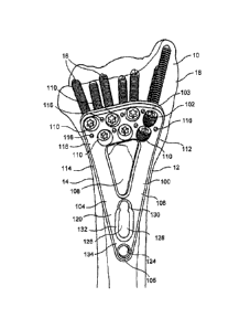
[0007] As shown in Figs. 1 - 3, a bone plate 100 according to a first
exemplary embodiment
of the present invention comprises a first wall 102 at a first end 103 and
second and third walls
104, 106, respectively, converging at a second end 105 so that the bone plate
100 has a
substantially triangular outer profile when viewed from above a surface of the
bone plate 100
which, when in a desired location on a target bone, faces away from the bone.
As would be
understood by those skilled in the art, when viewed from a side thereof, the
bone plate 100
preferably has a curve corresponding to a shape of the portion of bone to
which it is to be
secured. It is noted that the angles between each of the first, second, and
third walls 102, 104,
106 and the dimensions of each of these walls may be modified as needed to
suit the dimensions
of a target bone 10, as those skilled in the art will understand. The bone
plate 100 of the present
invention may be formed, for example, of titanium, stainless steel,
polyetheretherketone
("PEEK") or radiolucent PEEK as those skilled in the art will understand. A
window 108 having
a profile substantially matching the outer profile of the bone plate 100
extends through a center
thereof. In an exemplary embodiment, the window 108 is positioned so that a
width of each of
the second and third walls 104, 106 is substantially the same. The window 108
permits viewing
4
CA 02775735 2012-03-27
WO 2011/066280
PCT/US2010/057802
of a bone fracture line therethrough to aid in positioning of the bone plate
100 over a target
portion of the bone 10 as would be understood by those skilled in the art. In
a preferred
embodiment, a width of the first wall 102 is greater than the width of the
second and third walls
104,106, so that the first wall 102 can accommodate two substantially parallel
lines of screw
holes distributed along its length. Specifically, the first wall 102 is
configured for placement
over a distal portion of the radius 10 (i.e., the portion of the radius
adjacent the hand while the
proximal portion of the radius is adjacent the elbow) and comprises a set of
screw holes 110
extending therethrough, the screw holes 110 all having substantially the same
diameter (e.g., 3.5
mm.) or, in another embodiment, having different diameters to permit the
insertion of different
sized bone screw therethrough. Specifically, in the embodiment of Figs. 1- 3,
two rows of screw
holes 110 are provided in the first wall 102 -- a first row adjacent to the
first end 103 having four
screw holes 110 and a second row of three screw holes 110 each being aligned
with a gap
between adjacent screw holes 110 of the first row. It is noted, however, that
the screw holes 110
in the second row may also be longitudinally aligned with the screw holes 110
of the first row or
in any other spatial relation thereto without deviating from the spirit and
scope of the present
invention.
[0008] Each of the screw holes 110 defines an axis angled to guide a bone
fixation element
(e.g., bone screw 16) therethrough into the bone 10 along a desired axis which
preferably does
not intersect within the bone with any of the other screw hole axes. In
addition, the screw holes
110 are configured so that a bone screw 16 inserted therethrough extends to an
extremity of the
bone 10 without interfering with any of the other bone screws 16 and without
extending through
an opposing cortical surface of the bone 10. Specifically, screw holes 110
adjacent to the right
and left lateral walls 112, 114 of the bone plate 100 are angled so that bone
screws 12 inserted
therethrough extend outward toward the respective right and left lateral edges
12, 14 of the bone
10. The screw holes 110 are formed with internal threading configured to
permit locking,
screwable insertion of the heads of the bone screws 16 therein. Accordingly,
the exemplary bone
plate 100 of the present invention finds particular utility in bone fractures
resulting in two or
more bone fragments, as will be described in greater detail with respect to
the exemplary method
CA 02775735 2012-03-27
WO 2011/066280
PCT/US2010/057802
of the present invention. The angles of the screw holes 110 may also be
affected by a contour of
the bone plate 100. Specifically, as shown in Fig. 3, the bone plate 100 is
preferably contoured
so that a second surface 118 is seated against the bone in an operative
configuration. It is noted
that although the exemplary embodiment shown comprises first and second planar
portions 120,
122 positioned at a predetennined angle relative to one another, any
contouring of the bone plate
100 lies within the scope of the present invention and the contour of the
plate 100 may be
modified by the user (e.g., surgeon) to more closely match it to the anatomy
of the patient.
100091 The first wall 102 also comprises a plurality of Kirschner-wire ("K-
wire") holes 116
adjacent to the screw holes 110 configured to permit the insertion of a K-wire
(not shown)
therethrough to aid in positioning the bone plate 100 over the target portion
of bone, as those
skilled in the art will understand and as described in greater detail below.
[00010] The bone plate 100 also comprises a fixed angle threaded locking hole
124 extending
therethrough adjacent to the second end 105. The locking hole 124 may be
configured so that a
bone screw (not shown) inserted therethrough extends substantially
perpendicular to a plane of
the second planar portion 122 of the plate 100. The second planar portion 122
also comprises a
combination hole 126 having a first substantially elliptical compression hole
portion 128 and a
second substantially circular threaded portion 130. An axis of the combination
hole 126 extends
substantially perpendicularly through the bone plate 100 but, as those skilled
in the art will
understand, may be altered to permit insertion of a bone screw (not shown)
therethrough at any
desired angle relative to a plane of the second planar portion 122.
Specifically, the non-threaded
portion 128 comprises a substantially rounded tapered portion 134 extending
into the bone plate
100 from a first surface 132 by a predetermined distance and open to a
substantially
perpendicular portion 136.
1000111 Figs. 4 - 5 depict an exemplary method according to the present
invention. In a first
step, an incision is made through a portion of skin adjacent to the site of a
fracture 18. The bone
plate 100 is then positioned over the bone 10 so that the first wall 102 is
located over a distal
6
CA 02775735 2012-03-27
WO 2011/066280
PCT/US2010/057802
radius fracture site. Specifically, the plate 100 is positioned using an
aiming device 200
comprising a substantially cylindrical hooked arm 202, a longitudinal section
204 and a hooked
section 206 with a pointed tip 208. A handle 210 over the arm 202 includes a
through-hole 212
configured to slidably receive the arm 202 therethrough and a tightening
mechanism 214 to lock
the position of the handle 210 relative to the arm 202. The cross-sectional
shape and size of the
through-hole 212 is substantially similar to a cross-sectional shape and size
of a portion of the
arm 202 comprising a track 216 defined as a cut-out on the arm 202. The handle
210 is slidable
along the track 216 and is prevented from sliding over outlying portions of
the arm 202 due to
the increase in diameter at these portions. As those skilled in the art will
understand, the location
and dimensions of the track 216 prevent rotation of the handle 210 relative to
the arm 202. If
such a rotation is desired, however, the track 216 may be replaced with a
substantially cylindrical
reduced diameter portion of the arm 202. A free end of the handle 210
comprises a substantially
cylindrical pin 218 having approximately the same diameter as the screw holes
110 of the bone
plate 100. Accordingly, the pin 218 may be at least partially inserted into
the screw holes 110 to
aid in positioning of the bone plate 100 over the bone 10. The aiming device
100 is positioned
so that the pointed tip 208 is seated over an approximated midpoint of a
radial styloid of the
radius 10 and so that the pin 218 is positioned through a screw hole 110
located closest. to the
right lateral wall 112. In this position, the bone plate 100 is seated
proximate to the Watershed
Line of the radius 10 to prevent complications with sinews of the body, as
those skilled in the art
will understand. K-wires may be inserted through the K-wire holes 116 to aid
in positioning and
temporarily maintaining a position of the bone plate 100 over the bone 10.
[00012] The bone screws 16 are then screwed into the screw holes 110,
excluding the screw
hole 110 engaging the pin 218. It is noted that although seven plate holes 110
are depicted in the
bone plate 100, a physician or other user may choose to insert bone screws 16
through all or only
a select number of the screw holes 110¨ e.g., as required by the location and
number of
fragments of the bone 10. Furthermore, as those skilled in the art will
understand, aiming blocks
may be used to aid in insertion of the bone screws through the bone plate 100
and into the bone
10. Bone screws may also be inserted through one or both of the locking hole
124 and the
7
CA 02775735 2012-03-27
WO 2011/066280
PCT/US2010/057802
combination hole 126 either prior to or after the removal of the aiming arm
200 from the bone
10. As those skilled in the art will understand, a bone screw (not shown) may
be inserted
through the non-threaded portion 128 of the combination hole at any desired
angle or may be
inserted through the threaded portion 130 at an angle substantially
perpendicular to a plane
housing the second planar portion 122. The exemplary system and method of the
present
invention permits the use of fixed angle locking screws in the bone plate 100
while still
permitting an optimal placement of bone screw 16 in the radial styloid of the
radius 10.
Furthermore, the extraarticular bone fixation procedure according to the
present invention permit
the placement of the bone plate 100 close to the articular joint of the radius
10 while preventing
problems with sinews as commonly experienced with presently available bone
fixation devices.
[00013] As shown in Figs. 5 ¨ 6, a bone plate 300 according to a first
alternate embodiment of
the present invention, is substantially similar to the bone plate 100 of Figs.
1 - 3 except for the
arrangement of the holes extending through a second end 305 thereof
Specifically, whereas the
bone plate 100 comprises one locking hole 124 at the second end 105, the bone
plate 300
comprises a combination hole 326 at the second end 305 and a pair of threaded
locking holes 324
separated from the second end 305 by a predetermined distance. The combination
hole 326 is
formed substantially similarly to the combination hole 126 of Figs. 1 - 3,
having a non-threaded
elliptical section 328 and a threaded section 330. Like the bone plate 100,
the bone plate 300 is
substantially symmetrical across a longitudinal centerline L, the locking
holes 324 and
combination hole 326 being symmetrically disposed on the bone plate 300.
[00014] As shown in Fig. 7, a bone plate 400 according to a second alternate
embodiment of
the present invention is substantially similar to the bone plate 300 except
that the second end 405
thereof does not include a combination hole. Rather, the bone plate 400
comprises only two
threaded locking holes 424 symmetrically disposed at a location adjacent the
second end 405, the
threaded locking holes extending substantially perpendicularly to a plane
housing the bone plate
400, as described in greater detail in earlier embodiments.
8
CA 02775735 2012-03-27
WO 2011/066280
PCT/US2010/057802
[00015] As shown in Figs. 8A - 8B, a bone plate 500 according to a third
alternate
embodiment of the present invention is substantially similar to the bone plate
100 of Figs. 1 - 3
but comprises nine screw holes 510 disposed on a first wall 502 in a
distribution pattern
substantially similar to the distribution pattern of the screw holes 110 of
the bone plate 100.
Portions of the second and third walls 504, 506 adjacent to a second end 505
of the bone plate
500 are provided with a plurality of indentations 507 defining a plurality of
increased width
portions 509 housing threaded locking holes 524 and a combination hole 526
substantially
similar to the threaded locking hole 124 and the combination hole 126. The
combination hole
526 may be provided on the second wall 504 and the locking holes 526 on the
third wall 506 and
adjacent the second end 505, although any variation of these positions is also
envisioned. The
exemplary bone plate 500 is used for the fixation of a fracture 18' of a
radius in the same manner
described above.
[00016] An exemplary method of use of the bone plate 500 is substantially
similar to the
method discussed above with respect to the bone plate 100. However, due to the
location of the
fracture being medial of the first wall 502, an additional strengthening means
may be employed
with the bone plate 500. Specifically, a guide hole 532 may be drilled through
a portion of the
bone 10 positioned through a window 508. A washer 534 may then be positioned
over the guide
hole 532 so that an opening 534 of the washer is aligned with the guide hole.
A bone screw 536
may then be used to secure the washer to the bone 10. In an exemplary
embodiment, the washer
534 may be smaller than the window 508 so that the washer 534 does not
interfere with the bone
plate 500. The washer 534 may be formed of the same material as the bone plate
500 or may be
formed of another material known in the art.
[00017] As shown in Fig. 9, a bone plate 600 according to yet another
embodiment of the
present invention is substantially similar to the bone plate 500 except that
an outer profile of the
bone plate 600 and a window 608 are shaped differently. Specifically, an outer
profile of the
bone plate 600 may be substantially similar to the outer profile of the bone
plate 100 while the
window 608 is formed as an oblong shape having two indentations 607 extending
into a first wall
9
CA 02775735 2012-03-27
WO 2011/066280
PCT/US2010/057802
602. The indentations 607 may permit the insertion of a bone screw (not shown)
adjacent the
first wall 602 or may serve to increase visibility of a fracture site
therethrough.
[00018] As shown in Fig. 10, a bone plate 700 according to another embodiment
of the
present invention includes a substantially triangular end similar to the
plates depicted in the
earlier embodiments with a longitudinal extension 740 extending from a second
end 705 of
second and third walls 704, 706 configured to extend along a shaft of the
bone. In addition, a
first wall of the bone plate 700 comprises a plurality of variable angle screw
holes ¨ i.e., screw
holes which permit a user to insert a screw therethrough at any desired angle
relative to an axis
of the screw hole (within a permitted range of angulation). Specifically, the
first wall includes a
first row of variable angle screw holes including four screw holes 710
longitudinally offset from
one another and a second row having two screw variable angle holes 710
adjacent to right and
left lateral walls thereof. It is noted, however, that the number and
arrangement of the screw
holes 710 may be varied without deviating from the spirit and scope of the
present invention and
that any combination of fixed angle and variable angle holes may be included
as desired. As
would be understood by those skilled in the art, each of the variable angle
holes 710 includes a
central opening 712 a diameter of which is selected to engage a head of a
variable angle screw to
be inserted therein with a plurality of outer bores 714 (in this case four
outer bores 714)
extending through the plate and spaced from one another about a circumference
of the central
opening 712, Each of the outer bores 714 opens into the central opening 712 so
that a wall of the
central opening 712 is discontinuous about the circumference thereof. As would
be understood
by those skilled in the art, the wall of the central opening includes a
threading or a series of
ridges designed to engage corresponding features on the head of the screw to
be inserted
therethrough to lock each screw in a corresponding one of the holes 710 at a
desired angle
relative to a central axis of the central opening 712. The central opening 712
has a profile along
the central axis that is substantially hour glass shaped. That is, the central
opening 712 extends
into the plate from a proximal surface which faces away from the bone to a
bone facing surface
and has a diameter which tapers along the axis of the central axis from a
maximum at the
proximal surface to a minimum at a central portion configured to engage the
head of a screw and
CA 02775735 2012-03-27
WO 2011/066280
PCT/US2010/057802
then flaring outward to an opening at the bone facing surface having a
diameter greater than that
in the central portion. The wall of the central opening 712 in the central
portion and the
threading thereon includes a gap at each of the locations at which an outer
bore 714 opens
thereinto. The flared bone facing opening of the central opening and the outer
bores 714 permit
the shaft of a bone screw inserted thereinto to be angulated relative to the
central axis within a
permissible range ¨ e.g., up to 20 degrees as would be understood by those
skilled in the art.
[00019] A plurality of K-wire holes 716 are provided to aid in temporarily
positioning the
bone plate 700 over a bone. A window extending through the bone plate 700 is
substantially
teardrop shaped and reduced in width toward the second end 705. The
longitudinal extension
740 comprises a first combination hole 726 and a second combination hole 728
in longitudinal
alignment with one another. The first combination hole 726 in this embodiment
is formed
substantially similarly to the combination hole 126 while the second
combination hole has two
substantially circular portions open to one another, as those skilled in the
art will understand. An
outer profile of the variable angle locking compression bone plate 700 may be
especially useful
for the fixation of long bones or bones with multiple fracture sites.
[00020] As shown in Fig. 11, a bone plate 800 includes seven variable angle
screw holes 810
in a first wall 802 but is otherwise constructed similarly to the plate 700
described above.
As shown in Fig. 12, a bone plate 900 according to yet another embodiment of
the present
invention is substantially similar to the bone plate 700 of Fig. 10 except
that the first wall 902
thereof includes, in addition to the variable angle holes 910 similar to those
of the plate 700, a
variable angle combination hole 912 including two variable angle holes
adjacent to one another
and which are open to one another. The variable angle combination hole 912
includes two
central openings 914 side by side with central axes of each of these openings
914 separated from
one another by a distance less than a diameter of the openings 914 at a
proximal surface of the
plate 900 (i.e., a surface which faces away from the bone) so that the
proximal ends of the
openings 914 intersect with one another. In addition, each of the central
openings 914 is
surrounded by three outer bores 916 with the position which would be taken by
an equally
11
CA 02775735 2012-03-27
WO 2011/066280
PCT/US2010/057802
spaced fourth outer bore 916 being the location of a gap 918 opening the two
central openings
914 to each other. The gap 918 is preferably no wider than the openings in the
wall of the
central openings 914 formed by each of the outer bores 916. Thus, the gap 918
does not decrease
the extent of the threaded walls of the central openings 914 available to
engage the heads of bone
screws inserted thereinto. Furthermore, in addition to an elliptical
combination hole 926, a
longitudinal extension 940 of the bone plate 900 also comprises two
substantially circular
combination holes 928. The bone plate 900 is configured to be substantially
symmetrical along a
longitudinal centerline LC thereof. The bone plate 900 also comprises a window
908 formed
substantially similarly as the window 108 of Fig. 1 with the exception of a
substantially circular
additional opening 909 provided on the first wall 902, the opening 909 being
positioned adjacent
to and being open to the window 908. The opening 909 also extends through the
bone plate 900
from the first surface facing away from the bone to a bone facing surface
thereof.
[00021] Figs. 13-16 depict an aiming device 1000 according to another
exemplary
embodiment of the invention. The aiming device 1000 is substantially similar
to the aiming
device 200 of Figs. 4-5 with the exception of the details highlighted below,
The aiming device
1000 comprises a substantially cylindrical hooked arm 1002, a longitudinal
section 1004 and a
hooked section 1006 configured to receive a cannulated targeting tip 1008
formed substantially
similar to the pointed tip 208. Specifically, the cannulated targeting tip
1008 is formed as a
substantially cylindrical element having a plurality of longitudinal grooves
1010 configured to
aid in gripping and manipulation thereof by a physician or other user. The
cannulated targeting
tip 1008 comprises a longitudinal bore 1012 extending therethrough configured
to align with a
bore 1014 extending through the hooked section 1006 of the aiming aim 100. The
cannulated
targeting tip 1008 is configured to be detachable from the hooked arm 1006 to
permit attachment
of screws of different diameters thereto. Specifically, the cannulated
targeting tip 1008 may
optionally be removed and replaced with another pointed tip (not shown)
configured to permit
attachment to a bone fixation device (not shown) having a larger or smaller
diameter than a bone
fixation device 1032 or to permit insertion of a drill bit 1018 or other
device therethrough.
Similarly, the bore 1014 may be dimensioned as needed to permit insertion of
the required drill
12
CA 02775735 2012-03-27
WO 2011/066280
PCT/US2010/057802
bit 1018 therethrough, as discussed in greater detail hereafter. The
cannulated targeting tip 1008
further comprises one or more barbs 1016 at a distal end thereof configured
and dimensioned to
apply a gripping force to an approximated midpoint of a radial styloid of the
bone. As described
in greater detail earlier, such a positioning of the aiming device 100 permits
the bone plate 100 to
be seated proximate to the Watershed Line of the bone 10 to prevent
complications with sinews.
The exemplary cannulated targeting tip 1008 of the present invention permits a
physician or
other user to insert the drill bit 1018 through the hooked section 1006 to
drill a bore into the bone
after the aiming device 1000 has been positioned thereover in a target
alignment.
[00022] Similar to the device 200, the aiming device 1000 also comprises a
handle 1020
having a first through-hole 1022 at a first end thereof configured to receive
the longitudinal
section 1004 of the arm 1002 therethrough, a portion of the longitudinal
section 1004 comprising
a track 1024 to permit slidable movement of the handle therealong. A
tightening mechanism
1026 is provided on the first end of the handle 1020 to lock a position
thereof relative to the arm
1002. A second end of the handle 1020 comprises a second through-hole 1028
configured to
permit insertion of a first bone fixation device 1030 therethrough. The first
bone fixation device
1030 is preferably configured and dimensioned for insertion through a screw
hole 110 of the
bone plate 100, as will be described in greater detail below.
[00023] In accordance with an exemplary method according to the invention, the
bone plate
100 is positioned over the target portion of bone (not shown) using the aiming
device 2000 as
described in greater detail with respect to earlier embodiments. Once properly
positioned, the
tightening mechanism 1026 of the aiming device 1000 is tightened to lock a
position thereof over
the hone. In the locked position, the pointed tip 1016 is seated over the
approximated midpoint of
the styloid of the bone so that the bone pin 218 may be positioned through the
screw hole 110 of
the bone plate 100. K-wires may then be inserted through the K-wire holes 116
of the bone plate
100 to aid in temporarily fixing a desired position of the bone plate 100 over
the target portion of
bone. The bone screws 16 are then screwed into the screw holes 110, excluding
the screw hole
110 engaging the pin 218.
13
CA 02775735 2012-03-27
WO 2011/066280
PCT/US2010/057802
[00024] A physician or other use may then insert the drill bit 1018 through
the bore 1014 of
the hooked portion 1006 to drill a bore that will meet the bore housing the
pin 218. Specifically,
as shown in Fig. 14, the bone pin 218 may comprise an opening 218 extending
therethrough and
configured to permit insertion of the drill bit 1018 therethrough. Thus, as
the drill bit 1018 is
advanced into the bone, a distal end thereof may extend into the opening 219
of the bone pin
218. Once the drill bit 1018 has been advanced to the target depth and all
target bone screws
have been inserted through the bone plate 100, the bone pin 218 and the drill
bit 1018 are
removed from the bone. The tightening mechanism 1026 may then be released to
permit
removal of the aiming device 1000 from the bone. The first bone fixation
device 1030 may then
be inserted through the screw hole 110 of the bone plate 100. The second bone
fixation device
1032 is subsequently inserted through the borehole drilled by the drill bit
1018 until a distal end
thereof is threadedly received within an internal threaded cannula 1034 of the
first bone fixation
device 1030, as shown in Fig. 16. The cannula 1034 extends into a distal
portion of the first
bone fixation device 1030 by a depth selected such that the second bone
fixation device 1032
may be screwed thereinto until a head thereof engages an outer surface of the
styloid of the bone,
as those skilled in the art will understand. In an exemplary embodiment
according to the
invention, the second bone fixation device 1032 comprises a smooth outer wall
1036 and a
reduced diameter threaded portion 1038 configured to be received within the
cannula 1034. In
this embodiment, the second bone fixation device 1032 is locked against the
bone by
engagement of the threaded portion 1038 with internal threads of the cannula
1034. In another
embodiment, however, any portion of an outer wall of the second bone fixation
device 1032 may
be threaded to increase a holding strength thereof within the bone. Similarly,
the first bone
fixation device 1030 is depicted with a discrete portion of threading 1040 on
an outer wall
thereof. It is further noted that any portion of the first bone fixation
device 1030 may be
provided with external threading without deviating from the scope of the
invention.
[00025] It will be understood by those of skill in the art that the bone
plates of the present
invention may be provided with any of a plurality of other features without
deviating from the
14
CA 02775735 2012-03-27
WO 2011/066280
PCT/US2010/057802
scope of the present invention. Specifically, the bone plates may be provided
with any number
of indentations, curves or twists to aid in alignment with the bone.
Furthermore, the bone plate
and window are not limited to triangular shapes and may alternately be formed
of any other
ringed shape (e.g., square, rectangular, elliptical, etc.).
[000261 It will be apparent to those skilled in the art that various
modifications and variations
can be made in the structure and the methodology of the present invention,
without departing
from the spirit or the scope of the invention. Thus, it is intended that the
present invention cover
the modifications and variations of this invention provided that they come
within the scope of the
appended claims and their equivalents.