Note: Descriptions are shown in the official language in which they were submitted.
CA 02775763 2012-07-30
54106-1133
MONITORING OF THE PRESENCE OFTWO FLAMES IN A-FUEL COMBUS11ON DEVICE
[0001]
BACKGROUND
[00021 The present invention relates to a monitoring device and a method for
the
Independent monitoring of the presence of a 'first flame and of a second flame
in such a fuel
combustion device.
[00031 Fuel combustion devices am used In, among other things, heating and/or
hot water
engineering and In.. industrial thermoprocessing equipment employed,
forexample, in the
smelting of metals or the firing of ceramics. Fuel combustion devices which
are used in heatlna
and/or hot water engineering and are contained In boilers or continuous flow
water heaters do
not normally only operate with a main flame, for actual heat generation, but
also have a second,
so-called pilot flame, which Is also ogled an Ignition flame. In this
document, fuel burning
devices which are also described as burner automate, fuel burners or simply
burners can, for
example, be gas-burners or all burner;.
[00041 In many types of burner, the pilot flame does not go out even when no
heat output Is
required. The purpose of the pilot flame Is thus only to assure rapid-ignition
of the main flame
when a fuel valve assigned to the main flame is opened. In other types of
burner the pilot flame
is extinguished in the Interim and Is only reignited shortly before the main
flame ignites, for
example by an electric Ignition. When the main flame is activated, the-burning
pilot flame
ensures that the main flame ignition process can take place in a controlled
and ordered manner.
[00051 'For reasons of operational reliability, relevant standards state that
it must be possible
to detect the presence of the main and/or the pilot flame Independently of one
another.
1
CA 02775763 2012-07-30
54106-1133
10006] The use of a UV detector for monitoring the presence of both a pilot
flame and a main
flame is known from technical research documentation such as
"Flammenuberwachung.an Ol-
and Gasbrennern", Siemens Building Technologies, CCIZ7302de, HVAC Products,
16.02.2005.
A UV detector of this kind, which Is also called a UV flame sensor, is formed
of a series circuit
made up of ohmic resistance, a UV cell and a diode. -
[0007] The UV cell of the UV detector has a glass flask made of UV permeable
quartz glass
and filled with noble gas. In the glass flask are two electrodes. If voltage
is applied between the
two electrodes and this voltage is increased, then when a critical voltage is
reached, glow
discharge (ignition) takes place. Electrons are emitted from the negative
electrode, are
accelerated toward the positive electrode and ionize the noble gas. This re
suits in a flow of -
current through the UV cell. The UV cells used for flame monitoring typically
exhibit this
behavior of self-ignition only at voltages of more than 700 V. UV cells behave
differently if they
are irradiated'by the flame being monitored with UV light of which the
wavelength is approx. 190
to 260 nm: in such cases, occurrence of the Ignition effect depends on the
intensity of the UV
radiation at effective voltages as low as approx. 200 V.
[0008] The diode of the UV detector assures half-wave rectification, so that
if the UV detector
is operating with an alternating voltage when a flame is present a pulsed
direct voltage is
generated. In the event of a short circuit in the connection cables of the UV
detector it, and thus
also the diode, Is bypassed, with the result that when the UV detector Is
operating with an
alternating voltage, alternating voltage Is generated instead of the pulsed
direct voltage,
including at the input of an amplifier circuit downstream from the UV
detector. In this way, the
presence of a flame is indicated by a pulsed direct voltage and a cable short
circuit is Indicated
by an alternating voltage.
10009] Monitoring the main flame and the pilot flame independently of one
another using a
UV detector in each case has the disadvantage that (a) a connection cable
(with two connection
wires) and (b) an amplifier circuit are needed for each of the two UV
detectors. Monitoring the
main flame and the pilot flame using a UV detector in each case is thus
relatively apparatus-
intensive.
SUMMARY
2
CA 02775763 2012-07-30
54106-1133
100101 As regards the complexity of the apparatus required, it is one
potential object to
simplify the process of independently monitoring two spatially separate flames
using a flame
detector in each case.
100111 The inventors propose a monitoring device for the independent
monitoring of the
presence of a first flame and of a second flame In a fuel combustion device.
The monitoring
device has (a) a first flame detector configured and arranged to receive a
first batch of radiation,
which is emitted by the first flame, (b) a second flame detector, configured
and arranged to
receive a second batch of radiation, which Is emitted by the second flame, (c)
a voltage
supplying device that is connected to the two flame detectors and Is
configured to apply an
alternating voltage with a first half wave and a second half wave to the two
flame detectors and
(d) an evaluation circuit that is connected to the two flame detectors via a
common signal input.
The two flame detectors are configured In such a way, and are wired in such a
way in relation to
the voltage supplying device and to the evaluation circuit that a first
measurement signal that is
present at the common signal input during the first half wave is indicative of
the intensity of the
first batch of radiation and a second measurement signal that is present at
the common signal
input during the second half wave is indicative of the intensity of the second
batch of radiation.
In addition, the evaluation circuit is configured to evaluate the first
measurement signal and the
second measurement signal independently of one another.
10012] The monitoring device described is based on the finding that if the two
flame detectors
are suitably wired then, despite the use of a common signal input, the two
flame detectors can
be read independently of one another, provided the first measurement signal Is
assigned
exclusively to the first flame detector and the second measurement signal is
assigned
exclusively to the second flame detector. In such cases, the first measurement
signal can only
occur during the first half wave of alternating voltage applied to both flame
detectors.
Accordingly, the second measurement signal can only occur during the second
half wave of
alternating voltage.
[0013] In simple terms, this means that the measurement signals of the two
flame detectors
are assigned to the first (pilot) flame or the second (main) flame on the
evaluation circuit by
separating the signals, taking account of both the positive and the negative
half wave. This
enables the intensities of the two flames to be evaluated separately in a
simple yet effective
manner.
3
CA 02775763 2012-07-30
54106-1133
[001441 The fuel combustion device can be any desired burner that Is used in
heating and/or
hot water engineering In particular. The fuel burned can be solid, liquid or
gaseous under normal
conditions. The monitoring device described currently appears to be
particularly suitable for
burners that bum gas or in some cases also oil.
[00151 The monitoring device described has the advantage over known flame
monitoring
devices that when only one flame monitor to which both flame detectors are
connected is used
which, In addition to a display device, has the voltage supplying device and
the evaluation circuit
described, the presence of each of the two flames can be monitored
independently. Efficient
monitoring of both a main flame and a pilot flame In a fuel combustion device
can thus be
achieved in a manner which is not apparatus-intensive. An additional connector
on the flame
monitor, for connecting the second flame detector, is not necessary, and only
a two-wire flame
detector connection lead is required for bridging the gap between the actual
fuel burning device
in which the two flames are burning and a switch cabinet in which, typically,
the flame monitor is
arranged.
[0016] It should be pointed out that the two flames mentioned can also be two
of the flames
in a so-called surface burner, which typically has multiple Individual flames,
each one of which is
assigned to at least one opening in a fuel line. Normally, when the surface
burners ignite, one
flame is ignited, which then ignites the fuel that is issuing from the
adjacent openings. In this
way, each of the individual flames Is ignited in turn. The fuel line can, for
example, be in
serpentine form, in order to cover a predefined surface area.
[0017] According to one exemplary embodiment the monitoring device also. has
(a) a
common voltage supply line that connects the voltage supplying device to both
the first flame
detector and the second flame detector and/or (b) a common measurement signal
line that
connects both the first flame detector and the second detector to the common
signal input of the
evaluation circuit.
[0018] The use of a common, In particular a single-wire (connection) lead to
supply the
voltage for the two flame detectors and/or a common, In particular a single-
wire (connection)
lead for the onward transmission to the evaluation circuit for measurement
signals generated by
the two flame detectors has the advantage that a single connection lead is in
each case
sufficient to connect the two flame detectors to the voltage supply and/or to
the evaluation
4
CA 02775763 2012-07-30
54106-1133
circuit. This advantageously reduces the number of cables required between the
voltage
supplying device and the two flame detectors and/or the number of cables
required between the
two flame detectors and the common signal input.
[0019] It should be pointed out that the common voltage supply line connects
one connection
on each of the two flame detectors to the voltage supplying device, while the
common
measurement signal line connects the other connection on each of the two flame
detectors to
the common signal input of the evaluation circuit.
[0020] According to another exemplary embodiment the first flame detector has
a first
electrically rectifying element and the second flame detector has a second
electrically rectifying
element, it being possible for the two rectifying elements to be wired
antiparallel in relation to the
voltage supplying device and to the common signal input. This has the
advantage that the two
half waves of alternating voltage, both of which are adjacent to the two flame
detectors, can be
easily and effectively separated between the two flame detectors. The result
is that, with each of
the flame detectors, only one half wave of alternating voltage supply
generates a measurement
signal that can be detected and evaluated as a positive or a negative half-
wave signal by the
evaluation circuit, independently of the other half-wave signal in each case.
[0021] If a minor adjustment is made to a known evaluation circuit such as the
flame signal
amplifier LME7 or Siemens' LMV flame signal amplifier it is possible for the
two (half wave)
measurement signals to be evaluated separately. It is, for example, possible
here for another
amplifier circuit to be provided, so that a separate amplifier circuit is used
for each of the. two
(half-wave) measurement signals.
[0022] The rectifying element can be a valve, and is preferably a diode made,
for example, of
a semiconductor material.
100231 According to another exemplary embodiment, the first flame detector
also has a first
radiation detector. and the second flame detector also has a second radiation
detector, and at
least one of the two radiation detectors is sensitive to electromagnetic
radiation In the region of
the ultraviolet spectral range. This has the advantage that the presence of at
least one flame is
detected on the basis of the proportion of UV In the electromagnetic emission
spectrum of the
flame. In this way, the Influence of disturbance in the region of the visible,
or infrared, spectral
range can be effectively eliminated.
CA 02775763 2012-07-30
54106-1133
[0024] The radiation detector that Insensitive in the ultraviolet spectral
range can, for
example, be the abovementioned UV cell with a glass flask, made of UV
permeable quartz, in
which there are two electrodes. The glass flask also contains a noble gas,
which is ionized by
UV radiation striking it, so that the UV cell becomes at least partially
electrically conducting.
Such a UV cell is particularly sensitive to radiation In the electromagnetic
spectral range of
between 200 nm and 260 nm.
[0025] It should be pointed out that It is preferable for both radiation
detectors to be sensitive
to electromagnetic radiation in the ultraviolet spectral range. it should also
be pointed out that
despite the current preference for using radiation detectors that are of the
same kind, it is also
possible to use a combination of different kinds of radiation detector, and In
particular of
radiation detectors that are sensitive in the ultraviolet spectral range.
[0026] According to another exemplary embodiment the evaluation circuit has a
filter circuit.
This has the advantage that the (half-wave) measurement signals of the two
flame detectors are
evened out in such a way that, instead of a pulsed direct voltage signal, an
evened-out direct
voltage signal can in each case continue to be processed on the evaluation
circuit. Preferably,
the filter circuit can be connected immediately downstream from the signal
Input.
[0027] The filter circuit can, for example, be a so-called RC filter circuit
with one or more RC
links, each of which has a resistance and a capacitor.
10028] According to another exemplary embodiment , the evaluation circuit has-
(a) a first
amplifier circuit that is configured exclusively to amplify the first
measurement signal, and (b) a
second amplifier circuit that is configured exclusively to amplify the second
measurement signal.
This has the advantage that the two measurement signals can not only be
detected
independently of one another but also be amplified and evaluated Independently
of one another.
Preferably, each of the two amplifier circuits has its own output, from which
a signal, in particular
a direct voltage signal that is indicative of the presence of the particular
flame, is emitted.
[0029] According to another exemplary embodiment, the evaluation circuit has a
data
processing unit that is configured to detect the. presence of a fault in an
electronic component of
the evaluation circuit and, in particular, to Identify the faulty component,
on the basis of a first
output signal from the first amplifier circuit and of a second output signal
from the second
amplifier circuit. This has the advantage that It makes simple automated fault
diagnosis on the
6
CA 02775763 2012-07-30
54106-1133
evaluation circuit possible, This can considerably improve the operational
reliability of the
monitoring device as a whole.
[0030] According to another exemplary embodiment, the first amplifier circuit
has a first
diode on the input side and the second amplifier circuit has a second diode on
the input side. In
this embodiment, one of the two diodes is connected to the common signal input
on the anode
side and the other diode is connected to the common signal Input on the
cathode side.
(0031] The use of two diodes connected opposite one another makes it possible
simply and
efficiently to separate the two with measurement signals linked to various
half waves, so that the
first measurement signal Is directed exclusively to the first amplifier
circuit and the second
measurement signal is directed exclusively to the second amplifier circuit.
[0032] It should be pointed out that the connection described, linking the
anode and cathode
to the common signal input, can be a direct connection or an indirect
connection. If it is an
indirect connection, at least one other electronic component is located
between the anode or
cathode and the common signal Input. In particular, the filter circuit
described above can be
between the anode or the cathode and the common signal input.
[0033] According to another exemplary embodiment the first diode is a first
Zener diode
and/or the second diode Is a second Zener diode.
[0034] It is known that in the forward direction, a Zener diode behaves like a
normal diode, in
the monitoring device described, normal behavior ensures that the two
measurement signals
are separated from one another and that each is directed to one of the two
amplifier circuits. If,
however, voltage that is greater than the specific breakdown voltage for the
Zener diode in
question is applied in the reverse direction, the Zener diode becomes low-
ohmic. In the
monitoring device described, this behavior can, if the Zener diode is of a
suitable size and, in
particular, if a suitable breakdown voltage is chosen, be used to detect a
short circuit in the
connection lead, in particular a short circuit between the voltage supply line
described above
and the common measurement signal line described above.
[0035] According to another exemplary embodiment, the magnitude of the
breakdown
voltage of at least one of the two Zener diodes Is such that the at least one
Zener diode (a) is
operated within a voltage range that is lower than the breakdown voltage if
the connection of the
7
CA 02775763 2012-07-30
54106-1133
two flame detectors to the voltage supplying device and to the common signal
input is fault-free
and (b) is operated within a voltage range that is higher than the breakdown
voltage if a short
circuit occurs between the voltage supplying device and the common signal
input.
[0036] The voltage range mentioned, which is higher than the voltage in the
reverse
direction, Is typically also described as the cutoff range- in this cutoff
range, the Zener diode has
lost its rectifying effect.
[0037] With the monitoring device described, if there is a short circuit,
particularly between
the common voltage supply line described above and the common measurement
signal line
described above, the Zener diode will be operating-with the alternating
voltage already supplied
by the voltage supplying device, if necessary after evening-out by the filter
circuit, also
described above. As, when there is a short circuit, the Zener diode is
operating with a higher
alternating voltage - unlike during fault-free operation of the monitoring
device, during which the
relevant flame detector, even when radiation is detected, ensures that there
Is at least a certain
drop in voltage - this short circuit can be detected on the basis of a very
slight change in the
alternating voltage -- in some cases due to the characteristics of the Zener
diode - that is fed
into the relevant amplifier circuit and emitted at an output of the amplifier
circuit The presence
of an output alternating voltage can thus be regarded as a reliable indicator
that there is a short
circuit, in particular between the common voltage supply line described above
and the
measurement signal line described above. Detection of a short circuit is thus
not only made
simple but also effective and reliable, and the operational reliability of the
monitoring device as a
whole is considerably Increased.
10038] It should be pointed out that the size of the drop in voltage via the
flame detector
depends to a large degree on the type of radiation detector used in the flame
detector in
question. If this is a UV cell, which is currently regarded as particularly
suitable, the drop in
voltage via the UV cell, even if comparatively high intensity of UV radiation
is shown to exist, is
in the region of 100 V. In the event of a short circuit, therefore, the
voltage of the common signal
input of the evaluation circuit is approx. 100 V higher. This increased
voltage then results, in
some cases following some voltage attenuation by the filter circuit described
above, in the Zener
diode in question being within its cutoff range, at least during one of the
two half waves of
alternating voltage. It is of course necessary to choose a Zener diode with a
suitable typical
S
CA 02775763 2012-07-30
54106-1133
breakdown voltage in order to detect the short circuit detection functionality
described above on
the basis of an alternating voltage output signal from the amplifier circuit
in question.
[0039] The inventors also propose a method for the independent monitoring of
the presence
of a first flame and of a second flame In a fuel combustion device. The method
described
proposes (a) applying an alternating voltage supplied by a voltage supplying
device with a first
half wave and a second half wave to a first flame detector and a second flame
detector, (b)
receiving a first batch of radiation, which is emitted by the first flame, by
the first flame detector,
(c) receiving a second batch of radiation, which is emitted by the second
flame, by the second
flame detector, (d) directing a first measurement signal present during the
first half wave from
the first flame detector to a common signal input of an evaluation circuit, it
being possible for the
first measurement signal to be indicative of the intensity of the first batch
of radiation, (e)
directing a second measurement signal present during the second half wave from
the second
flame detector to the common signal input of the evaluation circuit, it being
possible for the
second measurement signal to be indicative of the intensity of the second
batch of radiation,
and (f) monitoring the presence of the first flame and of the second flame by
the evaluation
circuit, on the basis of the first measurement signal and the second
measurement signal.
[00401 The method described is also based on the finding that if the two flame
detectors are
suitably wired then, despite the use of a common signal input, the two flame
detectors can be
read independently of one another, provided the first measurement signal can
be assigned
exclusively to the first flame detector and the second measurement signal can
be assigned
exclusively to the second flame detector. According to the proposals, this
assignment takes
place via the two half waves of the alternating voltage that is made available
to both flame
detectors by the voltage supplying device. In such cases, the first
measurement signal can only
occur during the first half wave of alternating voltage applied to both flame
detectors.
Accordingly, the second measurement signal can only occur during the second
half wave of
alternating voltage.
[0041] According to one exemplary embodiment, the method also proposes (g)
extinguishing
the first flame, (h) evaluating the first measurement signal and (1)
considering the monitoring
device to be faulty if the evaluation of the first measurement signal
incorrectly indicates the
presence of the first flame.
9
CA 02775763 2012-07-30
54106-1133
100421 The at least temporary extinguishing of the first flame has the
advantage that it
enables the proper functioning of the monitoring device to be easily checked.
In particular, a
short circuit between the abovementloned common voltage supply line and the
abovementioned
common measurement signal line can be detected because only in the event of a
short circuit of
that kind is there an alternating current signal at the common signal input,
even when the first
flame detector Is receiving no radiation at all.
(0043] The first flame can, for example, be extinguished by closing a valve
regulating the fuel
feed to the first flame. In such cases, however, at least some delay is to be
expected in the
evaluation of the first measurement signal, corresponding to the anticipated
time tag between
the closing of the valve and the actual extinguishing of the first flame. For
example, this delay
can be between 1 and 10 seconds, depending on the design of the fuel
combustion device in
question.
t00441 Advantageously, the first flame can be extinguished during so-called
Intermittent
operation of the fuel combustion device, as it is then not necessary to turn
off the first flame in a
separate operation with the sole purpose of checking the working order of the
monitoring
device.
[0045] To comply with relevant product standards for fuel combustion devices,
which can
also be called "bumer automats , the term "intermittent operation should be
understood to
mean an operating mode in which the flames are switched off at least once (x1)
every 24 hours.
As far as normal heating applications for use in living areas are concerned,
this requirement is
in most cases met, as burners are often activated several times per hour. The
fuel combustion
device described can therefore use the activation process to check that it is
in working order,
and in particular to -check its flame monitoring system. This ensures that the
flame monitoring
system is relatively frequently tested during intermittent operation.
[0046] It should be pointed out that the method described can also be
implemented in the
same way with the second flame.
[0047] It should also be pointed out that even in fuel combustion devices or
burners in which
at least one flame (the pilot flame) always remains on, a fault, in particular
a short circuit, can
still be detected- It is thus possible, for example, in the embodiment of the
monitoring device
described above, In which suitably sized Zener diodes are used in order, when
there is a voltage
CA 02775763 2012-07-30
54106-1133
breakdown in one of the half waves (in the other half wave, the Zener diode is
the
conducting diode in any case) and thus when alternating voltage is fed to the
relevant
amplifier circuit on the evaluation circuit, to detect a short circuit between
the
common voltage supply line and the common measurement signal line.
[0047A] According to one aspect of the present invention, there is provided a
monitoring device to independently monitor a first flame and a second flame in
a fuel
combustion device, comprising: a first flame detector, configured and arranged
to
receive a first batch of radiation, which is emitted by the first flame; a
second flame
detector, configured and arranged to receive a second batch of radiation,
which is
emitted by the second flame; a voltage supply device that is connected to the
first
and second flame detectors and is configured to apply an alternating voltage
with a
first half wave and a second half wave to the first and second flame
detectors; and an
evaluation circuit connected to the first and second flame detectors via a
common
signal input, wherein the first and second flame detectors are configured in
such way
that: a first measurement signal that is present at the common signal input
during the
first half wave is indicative of an intensity of the first batch of radiation,
and a second
measurement signal that is present at the common signal input during the
second
half wave is indicative of an intensity of the second batch of radiation, and
wherein
the evaluation circuit is configured to evaluate the first measurement signal
and the
second measurement signal independently of one another.
[0047B] According to another aspect of the present invention, there is
provided
a method for independently monitoring presence of a first flame and a second
flame
in a fuel combustion device, comprising: applying an alternating voltage with
a first
half wave and a second half wave, from a voltage supplying device to a first
flame
detector and a second flame detector; receiving a first batch of radiation at
the first
flame detector, the first batch of radiation being emitted by the first flame;
receiving a
second batch of radiation at the second flame detector, the second batch of
radiation
being emitted by the second flame; directing a first measurement signal
present
11
CA 02775763 2012-07-30
54106-1133
during the first half wave from the first flame detector to a common signal
input of an
evaluation circuit, wherein the first measurement signal is indicative of an
intensity of
the first batch of radiation; directing a second measurement signal present
during the
second half wave from the second flame detector to the common signal input of
the
evaluation circuit, wherein the second measurement signal is indicative of an
intensity
of the second batch of radiation; and monitoring the presence of the first
flame and of
the second flame at the evaluation circuit, based on the first measurement
signal and
the second measurement signal.
[0048] It should be pointed out that the embodiments are described in
reference to various aspects of the method or the device. However, on reading
this
document, it will be immediately clear to those skilled in the art that,
unless it is
explicitly stated otherwise, method features have corresponding device
features, and
vice versa.
BRIEF DESCRIPTION OF THE DRAWINGS
[0049] These and other objects and advantages of the present invention will
become more apparent and more readily appreciated from the following
description
of the preferred embodiments, taken in conjunction with the accompanying
drawings
of which:
Figure 1 shows a monitoring device according to a first exemplary
embodiment, in which rectifying diodes are used to separate the measurement
signals provided by two flame detectors.
Figure 2 shows a monitoring device according to a second exemplary
embodiment, in which Zener diodes are used to separate the two measurement
signals, so that a short circuit in the sensor can also be detected.
Figure 3 shows the logical output signals, which are adjacent to the two
outputs of the amplifier circuit shown in Figure 2, for various flame
constellations.
lla
CA 02775763 2012-07-30
54106-1133
Figure 4 shows the output signals, which are adjacent to the two
outputs of the amplifier circuit, for various flame constellations, as well as
for when
there is a short circuit in the sensor between the common voltage supply line
shown
in Figure 2 and the common measurement signal line.
Figure 5 shows a time chart of how a short circuit in the sensor between
the common voltage supply line shown in Figure 2 and the common measurement
signal line can be
lib
CA 02775763 2012-07-30
54106-1133
detected during intermittent operation of a fuel combustion device that has a
main flame and a
pilot flame.
DETAILED DESCRIPTION OF THE PREFERRED EMBODIMENT
[0050] It should be pointed out that features and components of various
embodiments that
are the same, or at least function in the same way, as the corresponding
features or
components of the embodiment in question have been given the same reference
numbers, or a
reference number that differs from the reference number of a (functionally)
corresponding
feature or a (functionally) corresponding component only in the first
character of its reference
number. To avoid unnecessary repetition, features or components already
illustrated by a
previously described embodiment will not be described In detail again at a
later point.
[0051] It should also be pointed out that the embodiments described below only
represent a
limited selection of possible variants. In particular, certain appropriate
combinations of the
features of individual embodiments can be made, so it will be apparent to the
person skilled in
the art that numerous different embodiments are disclosed with the variants
explicitly shown
here. _
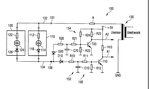
[0052] Figure 1 shows a monitoring device 100 according to a first exemplary
embodiment.
The monitoring device 100 has two flame detectors, a first flame detector 110
and a second
flame detector 120. According to the exemplary embodiment shown here, the
first flame
detector 110 monitors the presence of a main flame in a fuel combustion device
and the second
flame detector 120 monitors the presence of a pilot flame in the fuel
combustion device. As can
be seen in Figure 1, each of the two flame detectors 110, 120 has a
resistance, 112 and 122
respectively, a radiation sensitive sensor element (such as a UV cell or
photoelement), 114 and
124 respectively, and a rectifying diode, 116 and 126 respectively. The two
diodes 116 and 126
are connected, antiparallel relative to one another, to a common measurement
signal line 134.
[0053] Each of the two UV cells 114 and 124 has a glass flask made of a UV
permeable
quartz glass and filled with noble gas. In the glass flask are two electrodes.
If voltage is applied
between the two electrodes and, in addition, the noble gas is irradiated with
UV light emitted by
the main flame or the pilot flame, then the UV cell in question becomes at
least partially
electrically conducting and a current can flow through the corresponding flame
detector 110,
120.
12
CA 02775763 2012-07-30
54106-1133
[0054] The monitoring device 100 also has a voltage supplying device 130 which
is
configured as a transformer and arranged in a housing (not shown), and is
connected to the two
flame detectors 110 and 120 via a resistance R, a common voltage output 131
and a common
voltage supply device 132, The common voltage output 131 is configured as
connection contact
131 in the housing (not shown) of the monitoring device 100. According to the
exemplary
embodiment shown here, the transformer 130 performs a transformation during
which a 50 Hz
input signal with a network voltage (Unetwork) of 230 V is stepped up to a 50
Hz output signal
with a sensor voltage (Usensor) of approx. 300 V. It should be pointed out
that voltage
transformations with other frequencies and/or with other primary and/or
secondary voltage
values are of course possible. For example, in the US, an input signal with an
effective voltage
of 120 V and a frequency of 60 Hz is normally used.
[0065] The monitoring device 100 also has an evaluation circuit 150 which, in
turn, has a first
amplifier circuit 152 and a second amplifier circuit 154. The first amplifier
circuit 152 has a diode
1310 on the input side that is connected to a common signal input 138. The
second amplifier
circuit 154 has a diode D20 on the input side that is connected to the common
signal input 138.
According to the exemplary embodiment shown here the common signal input is
configured as
connection contact 138 in the abovementioned housing (not shown).
[0056] As can be seen in Figure 1, the two diodes 116 and D10 have the same
"polarity" in
relation to the common measurement signal line 134. This means that a voltage
passing
through the first flame detector 110 will be further processed exclusively
bythe first amplifier
circuit 152. Accordingly, the two diodes 125 and D20 also have the same
"polarity" in relation to
the common measurement signal line 134. This means that a voltage passing
through the
second flame detector 120 will be further processed exclusively by the second
amplifier circuit
154.
[0057] As an alternating voltage is applied to the two flame detectors 110 and
120 via the
common voltage supply fine 132, then the first flame detector 110 can, when
the main flame is
burning, only be electrically conducting during the positive half wave of
alternating voltage,
whereas the second flame detector 120 can only be conducting during the
negative half wave of
alternating voltage when the pilot flame is burning. The measurement signal
from the two flame
detectors 110 and 120 that is transferred to the evaluation circuit 150 via
the common
measurement signal line 134 is then separated from the two diodes D10 and D20
so that, as
13
CA 02775763 2012-07-30
54106-1133
already described above, the first amplifier circuit 152 is assigned to the
first flame detector 110
with the first output Al and the second amplifier circuit 154 being assigned
to the second flame
detector 120 with a second output A2.
[0058] As can be seen from Figure 1, the first amplifier circuit 152 has a
first low-pass filter
formed of a resistance R10 and a capacitor Cl0. Accordingly, the second
amplifier circuit 154
has a second low-pass filter formed of a resistance R20 and a capacitor C20.
These two filter
circuits 152 and 154 have the effect of evening out the pulsed direct voltage
adjacent to the filter
input, so that, in good approximation, a direct voltage signal is emitted at
the filter output in
question. This direct voltage signal is then amplified by the respective
amplifier circuit 152 or
154. As can be seen in Figure 1, the first amplifier circuit 152 has three
resistances R11, R12
and Rl 3 and a bipolar transistor TI 0. The second amplifier circuit 154 has
four resistances R21,
R22, R23 and R24 and a bipolar transistor T20. According to the exemplary
embodiment shown
here, the two amplifier circuits 152 and 154 operate, as can be seen in Figure
1, at two voltage
levels, 5 V and 0 V (GND).
10059] As such amplifier circuits are familiar to those skilled in the art,
the way in which they
function will not be explained in detail here. However, to those skilled in
the art it will be
immediately clear from the two amplifier circuits 152 and 164 shown in Figure
1 that If the first
flame detector 110 becomes at least partially conducting (the main flame is
on), a logic level of
approx. 0 V (Low) will be emitted at the first output Al. If the first flame
detector 110 receives no
UV radiation (the main flame is off), the first flame detector 110 performs a
shutoff function and
the logic level at the output Al will be approx. 5 V (High). Due to the
presence of the resistance
R24, if the second flame detector 120 becomes at least partially conducting
when it receives UV
radiation (the pilot flame is on), a logic level of approx. 5 V (High) is
emitted at the second
output A2. If the second flame detector 120 receives no radiation (the pilot
flame is off), the
second flame detector 120 performs a shutoff function and a logic level of
approx. 0 V (Low) will
be emitted at the output A2. By evaluating the two voltage levels it is thus
possible to monitor
both the presence of the main flame assigned to the first flame detector 110
and the presence of
the pilot flame assigned to the second flame detector. Because of the
antiparallel arrangement
of the flame detectors and despite the use of a common voltage supply line 132
and a common
measurement signal line 134, it is possible for the measurement signals of the
two flame
detectors to be clearly assigned to the two flames and for the two flames to
be independently
monitored.
14
CA 02775763 2012-07-30
54106-1133
[0060] Figure 2 shows a monitoring device 200 according to a second exemplary
embodiment. The monitoring device 200 has a voltage supplying device 230
configured as an
alternating voltage source and 0 direct voltage source 260. As can be seen by
comparing
figures 1 and 2,. an evaluation olrcuit 250 of the monitoring device 200 only
differs from the
evaluation circuit 150 shown In (Figure 1 In that. (a) instead of the usual
diodes Dl0 and D20, a
Zener diode ZD10 or ZD20 is used in each case, and that (b) a two-stage low-
pass filter circuit
240 Is also provided, which has two resistances RI and R2 and two capacitors
C1 and C2. The
separation (a) of the measurement signal from the first flame detector 110 and
(b) of the.
measurement signal from.the second flame detector 120 takes place In the same
way as in the
monitoring device 100 shown in Figure 1 and will therefore not be explained in
detail again.
10061] In the monitoring device 200 the two-stage low-pass filter circuit 240
ensures that the
measurement signals of both flame detectors 110 and 120 are evened out
immediately after the
common signal input 138.
.10062] The two Zener diodes ZD10 and ZD20 help ensure that, unlike with'the
monitoring
device 100, with the monitoring device 200 it is also possible to detect a
short circuit in the
sensor between the common vgitage supply line 132 and the common measurement
signal line
134. To this end, the levels of the breakdown or Zener voltages of the two
Zener diodes ZD10
and ZD20 are such that, in the event of a short circuit in the sensor, the
input voltage at the
common signal input 138 Is higher than the diode voltage of the two Zener
diodes.ZD10 and
ZD20. It should be borne in minks here that, In the event of a short circuit
in the sensor, the
voltage at the common signal input 1381s the full alternating voltage supplied
by the voltage
supplying deviceltransformer 130. By contrast, during normal operation of the
monitoring device
200 there Is at least a certain drop In the voltage over the UV cells (not
shown) of the two flame
detectors 110 and 120 when flames are burning, with the result that the
voltage at the common
signal input 138 is lower than this alternating voltage in the event of a
short circuit in the sensor.
Thus, in the event of a short circuit In the sensor, an alternating current
signal Is directed to the
two transistors TI 0 and T20. Tt>le following output signals are generated as
a result:
Output Al : Low -> main flame on
High -> main flame off
Alt. voltage -> short circuit in sensor
CA 02775763 2012-07-30
54106-1133
Output A2: Low -> pilot flame off
High -> pilot flame on
Alt. voltage -? short circuit in sensor
[0063] it should be pointed out that Figure 2 shows a circuit diagram for the
monitoring
device 200 that is suitable for a simulation program with which the following
operating conditions
can be simulated-
(A) The main flame is burning -> Switch S1 is off
(B) The pilot flame is burning -> Switch S2 is off
(C) Short circuit in sensor -} Switch 33 is off
[0064] The voltage signals, which are adjacent to outputs Al and A2, can be
shown for all
possible operating conditions on the evaluation unit 270 depicted as an
oscilloscope in the
diagram.
[0065] Figure 3 shows the logical output signals, which are adjacent to the
two outputs of the
amplifier circuit shown in Figure 2, for various flame constellations.
Reference number AA1
designates the output signal assigned to output Al shown in Figure 2.
Reference number AA2
designates the output signal assigned to output A2 shown in Figure 2. For
clarity's sake, the
voltage of the output signal AA1 is shown as being shifted by -2 V.
[0066] As already explained above, the level of the output signal AA2 is
"Love' when the pilot
flame is out. If the level of the output signal is "High", the pilot flame is
burning. The level of the
output signal AA1 is also 'High' when the main flame is out. If the level of
the output signal AA1
is at "Low", the main flame is burning.
[0067] Figure 4 shows the output signals AA1 and AA2, which are adjacent to
the two outputs
Al and A2 of the amplifier circuit 150, for various flame constellations, as
well as for when there
is a short circuit in the sensor between the common voltage supply line 132
shown in Figure 2
and the common measurement signal line 134. Provided there is no short circuit
in the sensor,
the levels of the output signals AA1 and AA2 assume the values "Low" and
"High" as described
above (AA1 is also shown as being shifted by -2 V in Figure 3).
16
CA 02775763 2012-07-30
54106-1133
(0068] In the exemplary scenario shown in Figure 4 there is a short circuit in
the sensor in
two time windows. The first short circuit in the sensor starts at to and ends
at tb, and the second
short circuit In the sensor starts at tc and ends at td = 12.8 seconds. As
already described
above, in both these time windows for the shortcuts in the sensor, the output
signal AA1 and the
output signal AA2 are alternating voltage signals and have the same frequency
as the
alternating voltage source 230 (see Figure 2).
[0069] Figure 5 shows a time chart of how a short circuit in the sensor
between the common
voltage supply line shown in Figure 2 and the common measurement signal line
can be
detected during intermittent operation of a fuel combustion device that has a
main flame and a
pilot flame. The monitoring device 200 shown in Figure 2, with the two Zener
diodes ZD10 and
ZD20,. is not absolutely necessary for this. Rather, it is also possible, as
explained below, for a
short circuit in the sensor to be detected on the basis of a time correlation
between a switching
cycle of connected fuel feed valves and the resulting (flame) signals emitted
at the outputs Al
and A2.
[0070] According to the exemplary embodiment shown here, a fuel feed valve for
the main
flame is opened at a point in time t1. The opened main flame valve Is
represented by the bar
581 in Figure 5. Provided the monitoring device is working correctly and the
main flame goes on
as a result - which is assumed in the following .- the presence of the main
flame is indicated at
the output Al at a point in time t2. The corresponding flame signal is
represented by the bar
581 a in Figure 5.
[0071] The time delay t2 - tl depends, among other things, on the time
required for the fuel
to be transported from the valve outlet to the location of the main flame. As
a result, it is possible
to calculate a maximum delay TSA1 for each fuel burning device, depending on
its design,
within which the main flame must go on. This delayTSA1 can be between 1 second
and 10
seconds, depending on the design of the fuel burning device in question.
However, if the first
flame signal does not go on within this time span TSA1 starting at t1, then it
can be assumed
that the flame monitoring device is defective.
[0072] If the valve for the main flame is closed at a point in time t5 then,
if the monitoring
device is functioning correctly, it is expected that the flame signal 581 a
for the main flame goes
17
CA 02775763 2012-07-30
54106-1133
off within a certain delay, at a point in time t6. If this is not the case, it
can be assumed that there
is a short circuit in the sensor.
[0073] The same applies to the opening (at a point in time t3) and closing (at
a point in time
t7) of the valve for the fuel feed for the pilot flame. In Figure 5, the
opened pilot flame valve is
represented by the bar 582. If the monitoring device is functioning correctly,
the flame signal
582a for the pilot flame will appear at a point in time t4 and disappear again
at a point in time t8.
It can also be assumed that there is a short circuit in the sensor if the
flame signal 582a is still
present even after the pilot flame valve has been closed for some time. In
this case as well, if
the monitoring device is functioning correctly, the time difference between t3
and t4= must not be
greater than a characteristic delay TSA2 before ignition of the pilot flame
[00741 Because, in principle, it has three different output signals ("Low",
"High" and
"Alternating voltage") that can be adjacent to either of the two outputs Al
and A2, the monitoring
device 200 shown in Figure 2 makes extensive fault monitoring possible. For
example, faults in
components of the evaluation circuit 150 can be reliably detected and the
components in
question actually identified. In this way, the requirements of, for example,
standards EN230 and
EN298 regarding behavior in the event of faults in components are fulfilled.
[0075] Table 1 below shows various faults in components of the monitoring
device 200,
together with the associated output signals at the outputs Al and A2. The
following
abbreviations are used in Table 1:
C: Collector
B: Base
E: Emitter
LIHIA: State remains unchanged at "Low", "High" or "Alternating current
signal", despite occurrence of fault in component
AC: Alternating current signal
SCS: Short circuit in sensor
FS: . Flame signal
(0076] In the case of the output Al, "High" means that there is no flame
signal from the main
flame and "Low" means that there is a flame signal from the main flame.
18
CA 02775763 2012-07-30
54106-1133
[0077] In the case of the output A2, "High" means that there is a flame signal
from the main
flame and "Low" means that there is no flame signal from the main flame.
[0078] The invention has been described in detail with particular reference to
preferred
embodiments thereof and examples, but it will be understood that variations
and modifications
can be effected within the spirit and scope of the invention covered by the
claims which may
include the phrase "at least one of A, B and C" as an alternative expression
that means one or
more of A, B and C may be used, contrary to the holding in Superguide V.
D!RECTV,
69 USPQ2d 1865 (Fed. Cir. 2004).
Table 1:
Type of fault Output Al Output A2
RI Interruption "LOW'
R2 Interruption "Hi h" "Low"
RIO Interruption "High"- UH/A
R11 Interruption "Hi h" UH/A
R12 Interruption UH/A UHIA
R13 Interruption "Low" UH/A
R20 Interruption UH/A "Low
R21 Interruption UH/A "Low"
R22 Interruption UH/A UHIA
R23 Interruption UHIA "Low"
R24 Interruption UHIA "Hi h"
C1 Interruption AC (SCS) AC (SCS)
Short circuit "High" "Low"
C2 Interruption AC (SGS) AC (SCS)
Short circuit "High" "Low"
C10 Interruption UHIA UHIA
No FS if A2 active
Short circuit "High" UH/A
C20 Interruption UH/A UH/A
No FS if Al active
Short circuit UHIA "Low"
D10 Interruption "High" L/H/A
Short circuit UH/A UH/A
D20 Interruption UHIA "Law"
Short circuit UH/A UH/A
110 Interruption C "High" UH/A
19
CA 02775763 2012-07-30
54106-1133
Interruption B '"High" LJH/A
Interruption E "High" L/H/A
Short circuit CE "Low" UH/A
Short circuit EB "High" LIH/A
Short circuit GB "Low" UH/A
T20 Interruption C UH/A "Low"
Interruption B UH/A "High"
Interruption E UH/A "High"
Short Circuit CE LJH/A
Short Circuit ES UH/A "High"
Short circuit CS UH/A "Love'