Language selection

Search

Patent 2775771 Summary

Third-party information liability

Some of the information on this Web page has been provided by external sources. The Government of Canada is not responsible for the accuracy, reliability or currency of the information supplied by external sources. Users wishing to rely upon this information should consult directly with the source of the information. Content provided by external sources is not subject to official languages, privacy and accessibility requirements.

Claims and Abstract availability

Any discrepancies in the text and image of the Claims and Abstract are due to differing posting times. Text of the Claims and Abstract are posted:

  • At the time the application is open to public inspection;
  • At the time of issue of the patent (grant).
(12) Patent Application: (11) CA 2775771
(54) English Title: SYSTEM TO STORE AND TO TRANSMIT ELECTRICAL POWER
(54) French Title: SYSTEME DE STOCKAGE ET DE TRANSMISSION D'ENERGIE ELECTRIQUE
Status: Dead
Bibliographic Data
(51) International Patent Classification (IPC):
  • H02J 3/02 (2006.01)
  • H02J 3/30 (2006.01)
  • H02J 4/00 (2006.01)
(72) Inventors :
  • STIESDAL, HENRIK (Denmark)
  • WOLF, ERIK (Germany)
(73) Owners :
  • SIEMENS AKTIENGESELLSCHAFT (Germany)
(71) Applicants :
  • SIEMENS AKTIENGESELLSCHAFT (Germany)
(74) Agent: SMART & BIGGAR
(74) Associate agent:
(45) Issued:
(86) PCT Filing Date: 2010-09-10
(87) Open to Public Inspection: 2011-04-07
Examination requested: 2015-05-12
Availability of licence: N/A
(25) Language of filing: English

Patent Cooperation Treaty (PCT): Yes
(86) PCT Filing Number: PCT/EP2010/063316
(87) International Publication Number: WO2011/039045
(85) National Entry: 2012-03-28

(30) Application Priority Data:
Application No. Country/Territory Date
09012402.5 European Patent Office (EPO) 2009-09-30

Abstracts

English Abstract

The invention relates to a system to store and to transmit electrical power. The system comprises at least one storage system, at least one bidirectional converter, at least one load coupled to a network, wherein the load is adapted to both, receive electrical power from the network and supply electrical power to the network. A first storage system is used to store electrical power of a power source. The first storage system is connected to a first bidirectional converter by a DC power transmission system. The first bidirectional converter is connected to an AC network and the AC network is connected to a first load.


French Abstract

La présente invention concerne un système pour stocker et transmettre de l'énergie électrique. Le système comprend au moins un système de stockage, au moins un convertisseur bidirectionnel, au moins une charge couplée à un réseau, la charge étant adaptée pour recevoir de l'énergie électrique du réseau ainsi que pour fournir de l'énergie électrique au réseau. Un premier système de stockage est utilisé pour stocker de l'énergie électrique d'une source d'énergie. Le premier système de stockage est connecté à un premier convertisseur bidirectionnel par un système de transmission d'énergie continue. Le premier convertisseur bidirectionnel est connecté à un réseau alternatif et ce dernier est connecté à une première charge.

Claims

Note: Claims are shown in the official language in which they were submitted.


1
Claims


1. System to store and to transmit electrical power,
comprising

at least one storage system comprising a central storage
system,
at least one bidirectional converter comprising a first
bidirectional converter,
at least one load coupled to an AC network and adapted to
both, receive electrical power from the AC network and supply
electrical power to the AC network, wherein the at least one
load comprises a first load,

- wherein the central storage system (CST1,...,CST3) is used to
store electrical power of a power source,

- wherein the central storage system (CST1,...,CST3) is
connected to the first bidirectional converter (CON12, CON22,
CON32) by a DC power transmission system,

- wherein the first bidirectional converter (CON12, CON22,
CON32) is connected to the AC network, and

- wherein the AC network is connected to the first load
(LOA11, LOA21, LOA31).

2. System according to claim 1,

- wherein the at least one bidirectional converter comprises
a second bidirectional converter (CON13, CON23, CON33) and
the at least one load comprises a second load (LOA12, LOA22,
LOA32),

- wherein the central storage system (CST1,...,CST3) is further
connected to the second bidirectional converter (CON13,
CON23, CON33) by the DC power transmission system,


2

- wherein the second bidirectional converter (CON13, CON23,
CON33) is connected to the AC network,

- wherein the AC network is connected to the second load
(LOA12, LOA22, LOA32), and

- wherein the AC network comprises a switch (SW11, SW21,
SW31) being used either to couple the first bidirectional
converter (CON12, CON22, CON32) and the first load (LOA11,
LOA21, LOA31) to the second bidirectional converter (CON13,
CON23, CON33) and the second load (LOA12, LOA22, LOA32) or to
decouple the first bidirectional converter (CON12, CON22,
CON32) and the first load (LOA11, LOA21, LOA31) from the
second bidirectional converter (CON13, CON23, CON33) and the
second load (LOA12, LOA22, LOA32).

3. System according to claim 1 or claim 2,

- wherein the at least one load (LOA11, LOA21, LOA31, LOA12,
LOA22, LOA32) is a vehicle for example a railway vehicle.

4. System according to one of the preceding claims,

- wherein the central storage system (CST1,...,CST3) is
connected to the DC transmission system either directly
and/or through an AC/DC converter (CON11, CON21, CON31)
and/or through a DC/DC converter (CON11, CON21, CON31).
5. System according to claim 4,

- wherein the AC/DC converter (CON11, CON21, CON31) and/or
the DC/DC converter (CON11, CON21, CON31) is a bidirectional
converter.


3

6. System according to one of the preceding claims,

- wherein the central storage system (CST1,...,CST3) comprises
a hydrogen storage and/or a molten salt storage and/or a
pumped hydro storage.

7. System according to one of the preceding claims,

- wherein the at least one storage system further comprises a
decentral storage system,

- wherein the decentral storage system (DST11, DST12, DST21,
DST22, DST31, DST32) is connected to the AC network through
one of that bidirectional converters (CON12, CON13, CON22,
CON23, CON32, CON33).

8. System according to claim 7,

- wherein the decentral storage system (DST11, DST12, DST21,
DST22, DST31, DST32) is connected to the DC transmission
system through one of that bidirectional converters (CON12,
CON13, CON22, CON23, CON32, CON33) and over that DC
transmission system to the central storage system
(CST1, ..., CST3).

9. System according to claim 7 or claim 8,

- wherein the decentral storage system (DST11, DST12, DST21,
DST22, DST31, DST32) comprises an electro-chemical, an
electrical or a mechanical storage.

10. System according to one of the preceding claims,


4

- wherein a controller (CTR1,...,CTR3) is connected to the at
least one storage system (CST1,...,CST3, DST11, DST12, DST21,
DST22, DST31, DST32).

11. System according to one of the preceding claims,

- wherein the at least one storage system (CST1,...,CST3,
DST11, DST12, DST21, DST22, DST31, DST32) and/or the at least
one converter (CON11, CON21, CON31, CON12, CON22, CON32,
CON13, CON23, CON33) and/or the at least one load (LOA11,
LOA21, LOA31, LOA12, LOA22, LOA32) and/or the switch (SW11,
SW21, SW31) and/or the AC network-is connected with an energy
management system, which is adapted to control energy flows.
12. System according to claim 11,

wherein the energy management system is adapted to control
the movement of the at least one load and/or the switching
operation of the switch (SW11, SW21, SW31, SW12, SW22, SW32)
for selectively powering a sub-section of the network.

13. System according to one of the preceding claims,,
wherein the power source comprises at least one power source
system (RES11, RES21, RES22, RES23, RES31, RES32) which is
connected to the DC transmission system.

14. System according to claim 13,
wherein the power source system (RES11, RES21, RES22, RES23,
RES31, RES32) comprises renewable power sources like wind
power sources, solar power sources or hydro power sources.
15. System according to claim 14,


wherein power source system comprises at least one back-up
power source (BAS1,...,BAS3) is connected to the DC
transmission system for compensating variations of the
renewable power source (RES11, RES21, RES22, RES23, RES31,
RES32).
Description

Note: Descriptions are shown in the official language in which they were submitted.


CA 02775771 2012-03-28
WO 2011/039045 1 PCT/EP2010/063316
Description

System to store and to transmit electrical power
Field of the invention

The present invention relates to an energy storage and
transmission system, in particular a DC transmission system.
Background of the invention

Transportation systems are often expected to overcome long
distances and to cross areas where suitable power generation
systems are not available. Direct current (DC) transmission
is a suitable transmission method for economic power
transmission over such long distances.

DC transmission systems are known for energy transfer between
two remote systems. Thereby, a first converter station is
usually located close to the power generation unit at one end
of a DC transmission line and a second converter station is
located at the other end of the DC transmission line in the
load center.

Some more sophisticated DC transmission systems comprise
bidirectional converter stations and allow for controlling
the current flow direction through the bidirectional
converter stations.

Worldwide transportation produces a huge amount of carbon
dioxid emissions and thus has a negative impact on the
environment. It is therefore desirable to provide
transportation systems, especially railway vehicles, with
energy from renewable energy sources.
However, transportation systems have to be highly reliable.
Renewable energy sources, on the contrairy, are intermittent
and their energy output quantity fluctuates.


CA 02775771 2012-03-28
WO 2011/039045 2 PCT/EP2010/063316
Besides, the power demand of transportation systems usually
fluctuates too because the vehicles start and stop regularly.
It is therefore the object of the present invention to
provide an energy storage and transmission system which
allows for compensating fluctuations of energy supply and
demand.

This object is achieved by means of the independent claim.
Advantageous features are defined in the dependent claims.
Further objects and advantages are apparent in the following
detailed description.

Summary of the invention
The present invention discloses a system to store and to
transmit electrical power, comprising at least one storage
system, at least one bidirectional converter, at least one
load coupled to a network, wherein the load is adapted to
both, receive electrical power from the network and supply
electrical power to the network, wherein a first storage
system is used to store electrical power of a power source,
wherein the first storage system is connected to a first
bidirectional converter by a DC power transmission system,
wherein the first bidirectional converter is connected to an
AC network and wherein the AC network is connected to a first
load.

The system according to the invention incorporates at least
one energy storage to compensate energy output variations of
at least one energy source. It thus renders possible the use
of energy sources with fluctuating energy output for
applications requiring an unvarying energy supply.

Thereby, the system according to the invention enables the
use of renewable energy sources, e.g. solar or wind power
plants, for these applications whithout requiring a national
or regional grid acting as energy storage.


CA 02775771 2012-03-28
WO 2011/039045 3 PCT/EP2010/063316
Applications requiring an unvarying energy supply comprise
transport systems. Thus, the system according to the
invention allows for climate-friendly energy supply of
transportation systems, for example railway systems.
Advantageously, the system according to the invention allows
for bidirectional energy flows. A load not only consumes
energy, it may also feed back energy into the system.
It is a further advantage of the present invention that
energy feeded in by the load may not only be stored locally,
but may also be transferred to the DC transmission system and
from the DC transmission system to another storage.
Brief description of the drawings

Embodiments of the present invention will now be described,
by way of example, with reference to the accompanying
drawings in which:

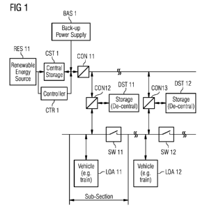
Fig. 1: shows a storage and transmission system with a power
source connected to the sending end of a DC transmission
system through a central storage
Fig. 2: shows a storage and transmission system with power
sources connected either directly or through a central
storage to the DC transmission system

Fig. 3: shows a storage and transmission system with several
power sources and a central storage wherein the power sources
and the storage are connected to the DC transmission system
As shown in figure 1 the system according to the invention
comprises a central storage system CST1. The central storage
system is connected to a power source system RES11 and is
used to store electrical power which allows for compensating
energy output variations of the power source system.


CA 02775771 2012-03-28
WO 2011/039045 4 PCT/EP2010/063316
The power source system RES11 comprises either a single power
source or several power sources wherein the several power
sources are managed in conjunction. Preferably, the power
source system comprises renewable power sources like wind or
solar power plants.

The aformentioned central storage system CST1 is furthermore
connected to bidirectional converter stations CON12, CON13 by
a High Voltage Direct Current power transmission system
hereinafter called HVDC transmission system. The HVDC
transmission system allows for economic power transmission
over long distances and for fast control of power flows, not
only for the HVDC link but also for surrounding electrical
systems.

The central storage system CST1 is connected to the HVDC
transmission system through an AC/DC or DC/DC converter
station CON11 and comprises a hydrogen storage, a molten salt
storage or a pumped hydro storage. Besides, a controller CTR1
is connected to the central storage system CST1.

In addition, a back-up power source BAS1 is connected to the
HVDC transmission system through the converter station CON11
for compensating variations of the renewable power source
system. The backup power source comprises one or more AC or
DC power sources and the converter station CON11 comprises an
AC/DC converter or a DC/DC converter, respectively.

The above-mentioned bidirectional converter stations CON12,
CON13, are connected to an AC supply network and loads LOA11,
LOA12 are coupled to that AC supply network. By way of
example these loads are railway vehicles.

The railway vehicles are adapted to both, receive electrical
power from the AC supply network and provide electrical power
to the AC supply network.


CA 02775771 2012-03-28
WO 2011/039045 5 PCT/EP2010/063316
As further shown in figure 1, the AC supply network comprises
switches SW11, SW21 which allow for segmenting the AC supply
network into sub-sections. The sub-sections can be powered
independently. Thus only the sub-sections on which a railway
vehicle is present could be provided with power.

Thereby, the switches or sub-section interrupters SW11, SW12
are used to couple the first converter station CON12 and the
associated first load LOA11 to the second converter station
CON13 and the associated second load LOA12 or to decouple the
first converter station CON12 and the associated first load
LOA11 from the second converter station CON13 and the
associated second load LOA12.

The bidirectional converter stations CON12, CON13 comprise
DC/AC converters. By means of the bidirectional converter
stations, on the one hand, power is feeded into the AC supply
network for example to accelerate a railway vehicle or to
maintain the vehicles speed, on the other hand, power is
harvested from the AC supply network for example during
deceleration of a railway vehicle.

Decentral energy storage units DST11, DST12 are either
connected to or integrated into these bidirectional converter
stations CON12, CON13 to absorb electrical power. Power
stored in the decentral storage units DST11, DST12 can be
provided to the railway vehicle. The decentral storage units
DST11, DST12 may comprise an electrochemical storage (e.g.
battery), an electrical storage (e.g. super cap), a
mechanical storage (e.g. flywheel energy storage) or any
combination thereof.

Energy harvested from the AC supply network may also be fed
back to the HVDC transmission system and from the HVDC
transmission system to the central storage CST1. Therefore
converter CON11 can be a bidirectional converter.


CA 02775771 2012-03-28
WO 2011/039045 6 PCT/EP2010/063316
In addition, the storage system CST1, DST11, DST12 and/or the
bidirectional converter CON12, CON13 and/or the load LOA11,
LOA12 and/or the switch SW11, SW12 and/or the network is
connected with an energy management system, which controls
energy flows within the system. It further may control the
movement of the load LOA11, LOA12 and the switching operation
of the switch SW11, SW12.

In an alternate embodiment shown in figure 2 further power
source systems are connected to the system in addition to the
main power source.

As shown in figure 2, the system comprises a central storage
system CST2 which is connected to a power source system
RES21.

That power source system RES21 comprises either a single
power source or several power sources wherein the several
power sources are managed in conjunction. Preferably, the
power source system RES21 comprises renewable power sources
like wind or solar power plants.

The aforementioned central storage system CST2 is connected
to bidirectional converter stations CON22, CON23 by an HVDC
transmission system. Thereby, the central storage system CST2
is connected to the HVDC transmission system directly as well
as through an AC/DC or DC/DC converter station CON21. The
central storage system CST2 comprises a hydrogen storage
and/or a molten salt storage and/or a pumped hydro storage.
Besides, a controller CTR2 is connected to the central
storage system CST2.

Moreover, a back-up power source BAS2 is connected to the
HVDC transmission system through the converter station CON21
for compensating variations of the renewable power source
system. The backup power source may comprise one or more AC
or DC sources and the converter station CON21 comprises an
AC/DC converter or a DC/DC converter, respectively.


CA 02775771 2012-03-28
WO 2011/039045 7 PCT/EP2010/063316
The embodiment of the invention shown in figure 2, comprises,
in addition to the main and backup power sources RES21 and
BAS2, further power source systems RES22, RES23 which are
connected to the HVDC transmission system. The further power
source systems can be located decentrally and may comprise
either a single power source or several power sources wherein
the several power sources are managed in conjunction. The
power source systems RES22 and RES23 may also comprise
renewable power sources.

The above-mentioned bidirectional converter stations CON22,
CON23 are connected to an AC supply network and loads LOA21,
LOA22 are coupled to the AC supply network. By way of example
the loads are railway vehicles.

The railway vehicles are adapted to both, receive electrical
power from the AC supply network and provide electrical power
to the AC supply network.
As further shown in figure 2, the AC supply network comprises
switches SW21, SW22 which allow for segmenting the AC supply
network into sub-sections. The sub-sections can be powered
independently. Thus only the sub-sections on which a railway
vehicle is present could be provided with power.

Thereby, the switches or sub-section interrupters SW21, SW22
are used to couple the first converter station CON22 and the
associated first load LOA21 to the second converter station
CON23 and the associated second load LOA22 or to decouple the
first converter station CON22 and the associated first load
LOA21 from the second converter station CON23 and the
associated second load LOA22.

The bidirectional converter stations CON22, CON23 comprise
DC/AC converters. By means of these bidirectional converter
stations, on the one hand, power is feeded into the AC supply
network for example to accelerate a railway vehicle or to


CA 02775771 2012-03-28
WO 2011/039045 8 PCT/EP2010/063316
maintain the vehicles speed, on the other hand, power is
harvested from the AC supply network for example during
deceleration of a railway vehicle.

Decentral energy storage units DST21, DST22 are either
connected to or integrated into these bidirectional converter
stations CON22, CON23 to absorb electrical power. Power
stored in the decentral storage units DST21, DST22 can be
provided to the railway vehicles. The decentral storage units
DST21, DST22 may comprise an electrochemical storage (e.g.
battery), an electrical storage (e.g. super cap), a
mechanical storage (e.g. flywheel energy storage) or any
combination thereof.

Energy harvested from the AC supply network may also be fed
back to the HVDC transmission system and from the HVDC
transmission system to the central storage system CST2.
Therefore the central storage system is directly connected to
the HVDC transmission system and converter CON21 is adapted
to allow for bidirectional energy flows.

In addition, the storage system CST2, DST21, DST22 and/or the
converter CON21, CON22, CON23 and/or the load LOA21, LOA22
and/or the switch SW21, SW22 and/or the network is connected
to an energy management system, which controls energy flows
within the system. It further may control the movement of the
load LOA21, LOA22 and the switching operation of the switch
SW21, SW22.

In a further alternate embodiment shown in figure 3, the
power source systems are located decentrally.

As shown in figure 3, a central storage system CST3 is again
connected to bidirectional converter stations CON32, CON33 by
an HVDC transmission system.

Thereby, the central storage system CST3 is connected to the
HVDC transmission system directly as well as through an AC/DC


CA 02775771 2012-03-28
WO 2011/039045 9 PCT/EP2010/063316
or DC/DC converter CON31. It comprises a hydrogen storage
and/or a molten salt storage and/or a pumped hydro storage.
The embodiment shown in figure 3, comprises power source
systems RES31 and RES32, which are connected to the HVDC
transmission system. As aforementioned, these and further
power source systems may be located decentrally. They are
adapted to provide energy to the central storage system CST3.

The power source systems RES31 and RES32 comprise either a
single power source or several power sources wherein the
several power sources are managed in conjunction. Preferably,
the power sources RES31, RES32 comprise renewable power
sources like wind or solar power plants.
In addition, a back-up power source BAS3 is connected to the
DC transmission system through the converter station CON31.
The backup power source may comprise one or more AC or DC
power sources and the converter station CON31 comprises an
AC/DC converter or a DC/DC converter, respectively.
The bidirectional converter stations CON32, CON33 are
connected to an AC supply network. The loads LOA31 and LOA32
are coupled to that AC supply network. By way of example
these loads are railway vehicles.

The railway vehicles are adapted to both, receive electrical
power from the AC supply network and provide electrical power
to that AC supply network.
As further shown in figure 3, the AC supply network comprises
switches SW31 and SW31 which allow for segmenting the AC
supply network into sub-sections. The sub-sections may be
powered independently. Thus only the sub-sections on which a
railway vehicle is present could be provided with power.
Thereby, the switches or sub-section interrupters SW31, SW32
are used to couple the first converter station CON32 and the


CA 02775771 2012-03-28
WO 2011/039045 10 PCT/EP2010/063316
associated first load LOA31 to the second converter station
CON33 and the associated second load LOA32 or to decouple the
first converter station CON32 and the associated first load
LOA31 from the second converter station CON33 and the
associated second load LOA32.

The bidirectional converter stations CON32, CON33 comprise
DC/AC converters. By means of these bidirectional converter
stations, on the one hand, power is feeded into the AC supply
network for example to accelerate a railway vehicle or to
maintain the vehicles speed, on the other hand, power is
harvested from the AC supply network for example during
deceleration of a railway vehicle.

Decentral energy storage units DST31, DST32 are either
connected to or integrated into these bidirectional converter
stations CON32, CON33 to absorb electrical power. Power
stored in the decentral storage units can be provided to the
railway vehicle. The decentral storage units may comprise an
electrochemical storage (e.g. battery), an electrical storage
(e.g. super cap), a mechanical storage (e.g. flywheel energy
storage) or any combination thereof.

Energy harvested from the AC supply network may also be fed
back to the HVDC transmission system and from the HVDC
transmission system to the central storage CST3. Therefore
the central storage system is directly connected to the HVDC
transmission system and converter CON31 is adapted to allow
for bidirectional energy flows.
In addition, the storage system CST3, DST31, DST32 and/or the
converter CON31, CON32, CON33 and/or the load LOA31, LOA32
and/or the switch SW31, SW32 and/or the network is connected
with an energy management system, which controls energy flows
within the system. It further may control the movement of the
load LOA31, LOA32 and the switching operation of the switch
SW31, SW32.

Representative Drawing
A single figure which represents the drawing illustrating the invention.
Administrative Status

For a clearer understanding of the status of the application/patent presented on this page, the site Disclaimer , as well as the definitions for Patent , Administrative Status , Maintenance Fee  and Payment History  should be consulted.

Administrative Status

Title Date
Forecasted Issue Date Unavailable
(86) PCT Filing Date 2010-09-10
(87) PCT Publication Date 2011-04-07
(85) National Entry 2012-03-28
Examination Requested 2015-05-12
Dead Application 2017-09-12

Abandonment History

Abandonment Date Reason Reinstatement Date
2016-09-12 FAILURE TO PAY APPLICATION MAINTENANCE FEE
2016-11-30 R30(2) - Failure to Respond

Payment History

Fee Type Anniversary Year Due Date Amount Paid Paid Date
Application Fee $400.00 2012-03-28
Maintenance Fee - Application - New Act 2 2012-09-10 $100.00 2012-08-13
Maintenance Fee - Application - New Act 3 2013-09-10 $100.00 2013-08-14
Maintenance Fee - Application - New Act 4 2014-09-10 $100.00 2014-08-08
Request for Examination $800.00 2015-05-12
Maintenance Fee - Application - New Act 5 2015-09-10 $200.00 2015-08-12
Owners on Record

Note: Records showing the ownership history in alphabetical order.

Current Owners on Record
SIEMENS AKTIENGESELLSCHAFT
Past Owners on Record
None
Past Owners that do not appear in the "Owners on Record" listing will appear in other documentation within the application.
Documents

To view selected files, please enter reCAPTCHA code :


To view images, click a link in the Document Description column. To download the documents, select one or more checkboxes in the first column and then click the "Download Selected in PDF format (Zip Archive)" or the "Download Selected as Single PDF" button.

List of published and non-published patent-specific documents on the CPD .

If you have any difficulty accessing content, you can call the Client Service Centre at 1-866-997-1936 or send them an e-mail at CIPO Client Service Centre.


Document
Description 
Date
(yyyy-mm-dd) 
Number of pages   Size of Image (KB) 
Abstract 2012-03-28 2 69
Claims 2012-03-28 5 145
Drawings 2012-03-28 3 41
Description 2012-03-28 10 428
Representative Drawing 2012-05-16 1 6
Cover Page 2012-06-01 2 42
Abstract 2014-04-07 1 16
Claims 2014-04-07 4 105
Description 2014-04-07 11 448
PCT 2012-03-28 22 793
Assignment 2012-03-28 2 60
Prosecution-Amendment 2014-04-07 12 365
Prosecution-Amendment 2015-05-12 2 79
Correspondence 2015-01-15 2 63
Examiner Requisition 2016-05-30 4 242