Note: Descriptions are shown in the official language in which they were submitted.
CA 02775875 2012-04-30
EARTH DRILLING APPARATUS AND METHOD
FIELD OF THE INVENTION
This invention relates to earth drilling, and
particularly to improvements by which insertion of well
casing can be carried out more efficiently.
BACKGROUND OF THE INVENTION
A water well is typically drilled by a portable drill
rig having a mast. The drill stem, composed of one or more
lengths of drill pipe, and having a cutting bit at one end,
is rotated by a top head connected to the opposite end of
the drill stem. The top head is movable lengthwise along
the mast, and descends with the drill stem as drilling
proceeds. When a major part of the length of an uppermost
length of pipe in the drill stem is in the bore hole and
the top head is near the lower end of the mast, the top
head is disconnected from the drill stem, and moved upward
toward the upper end of the mast. Another length of drill
pipe is then moved into place between, and connected to,
the top head and the part of the drill stem extending
upward from the bore hole, and drilling is resumed.
In well drilling, it is common practice to use well
casing to prevent collapse of the walls of a borehole while
drilling is taking place. A well casing is typically
composed of one or more lengths of pipe having a diameter
greater than that of the drill pipe.
In order to set well casing in place, the bore hole is
first drilled to the desired depth of the casing using a
1
CA 02775875 2012-04-30
bit having a diameter that is larger than the diameter of
the casing. When the bore hole reaches the desired casing
depth, the drill string is withdrawn from the bore hole.
As the drill string is withdrawn, drill pipe sections are
removed from the drill string one section at a time until
the drill string, including the bit, are removed from the
hole. Then, the casing sections are introduced one section
at a time through an opening in a drive table movable along
the mast of the drill rig. The first section of casing to
be introduced is lowered down the open hole, supported by a
plate lifting device hooked to a cable attached to a jib
boom.
The lengths of casing can be brought into position
above the table by means of pipe-handling arms, or
alternatively by a cable connected to a jib boom. The
lengths of casing can then be aligned with the bore hole by
hand, while still attached to the cable.
Each length of casing is typically provided with a tab
welded near its upper end for engagement with the table in
order to prevent the casing from being dropped into the
bore hole. When each length of casing is introduced to the
extent such that its tab is in, or nearly in, engagement
with the table and the table is in its lowermost position,
a next length of casing is attached to the casing already
in place, usually by welding, but sometimes by engagement
of threads on the casing sections. After the attachment is
completed, the tab is cut off and the insertion of the
casing is continued. When the casing is in place, grout is
introduced into the space surrounding the casing. Then,
2
CA 02775875 2012-04-30
drilling is continued, using a bit having a diameter
smaller than the internal diameter of the casing.
The conventional process is particularly time-
consuming because it requires disassembly and removal of
the drill string after the casing bore is drilled and
reassembly of the drill string in order to continue
drilling beyond the lower end of the casing. There is also
a risk that the casing will be accidentally dropped into
the casing bore necessitating retrieval, which can be
difficult.
SUMMARY OF THE INVENTION
A first aspect of the invention is a method in which
the introduction of casing is carried out simultaneously
with drilling, thereby avoiding the time-consuming steps of
removing the drill string from the casing bore before the
casing is introduced, and reassembling the drill string for
further drilling beyond the lower end of the casing.
More particularly, drilling of a well is carried out
using a drill rig comprising an elongated mast having upper
and lower ends, a mast support, a top head for rotating a
drill string, the top head being movable lengthwise along
the mast, and a casing rotator connected to the mast. The
casing rotator includes a rotatable chuck for gripping and
rotating a length of well casing. The drilling process
comprises the following sequence of steps. A length of
drill pipe is connected to the top head. A length of well
casing is then slid onto the length of drill pipe connected
to the top head until the end of the length of drill pipe
3
CA 02775875 2012-04-30
remote from the top head is exposed. The length of drill
pipe is then connected to the upper end of a drill string
already in a bore hole, thereby lengthening the drill
string. The length of well casing is connected to the
upper end of a well casing surrounding the drill string
thereby lengthening the well casing. The drill string has
a cutting bit at its lower end, and the well casing
surrounding the drill string has a drive shoe at its lower
end. Drilling of the well is carried out by rotating the
drill string by means of the top head, and simultaneously
rotating and lowering the well casing into the well by
means of the casing rotator. The foregoing sequence of
steps is repeated until the well casing is inserted to a
desired depth.
After the repetition of the above-described sequence
of steps is discontinued, and, with the well casing
inserted to the desired depth, drilling can be continued by
connection of additional lengths of drill pipe to the drill
string, and rotating the drill string by means of the top
head.
The steps of rotating the drill string by means of the
top head, and simultaneously rotating and lowering the well
casing, are preferably carried out by rotating the drill
string and well casing in opposite directions.
A second aspect of the invention is a drill rig
construction which is better adapted to the above-described
simultaneous drilling and casing introduction method.
Preferably, the casing rotator is fixed to the mast, the
mast is movable lengthwise relative to the mast support,
4
CA 02775875 2012-04-30
and the well casing is lowered by repeatedly moving the
mast lengthwise relative to the mast support, and relative
to the top head.
More particularly, a drill rig in accordance with this
second aspect of the invention comprises an elongated mast,
a mast support, a top head for rotating a drill string, the
top head being movable lengthwise along the mast, and a
casing rotator having a rotatable chuck for gripping and
rotating a length of well casing. The casing rotator is
mounted at a fixed position along the length of the mast,
and the mast is movable relative to the mast support along
the mast's direction of elongation. A well casing can be
advanced into a well by simultaneous rotation of the chuck
and lengthwise movement of the mast. The well casing is
advanced by gripping the casing with the chuck of the
casing rotator, and rotating the casing while
simultaneously lowering the mast. When the casing rotator
reaches the lower limit of its range of movement, the grip
of the casing rotator on the mast is released, the mast is
raised, and the grip of the casing rotator on the casing is
reestablished so that further advancing movement of the
casing can take place by lowering of the mast.
The top head, which rotates the drill string, is
guided by the mast, but the mast and top head move
independently along the direction of the length of the
mast. Consequently, drilling can proceed continuously while
the well casing is being advanced by up and down movement
of the mast, being interrupted only for the insertion of
5
CA 02775875 2012-04-30
additional lengths of drill pipe and additional lengths of
well casing.
The fact that the casing rotator is located at a fixed
position along the length of the mast ensures that it does
not interfere with the movement of lengths of drill pipe
and lengths of well casing into alignment with the drill
string and casing, respectively already in place.
Traditional pipe handling equipment and techniques can
therefore be used. In addition, since drilling and
advancement of the casing take place simultaneously, the
top head can remain substantially at a constant position on
the mast throughout the portion of each drilling cycle
during which the mast is moving downward to advance the
casing. Consequently, it becomes easier to control the
advancing movement of the drill string and the casing.
Objects and other advantages of the invention will be
apparent from the following description when read in
conjunction with the drawings.
BRIEF DESCRIPTION OF THE DRAWINGS
FIGs. 1-8 are perspective views of a drill rig in
accordance with the invention, showing successive stages of
the process of introducing a length of well casing into a
bore hole.
DETAILED DESCRIPTION OF THE PREFERRED EMBODIMENTS
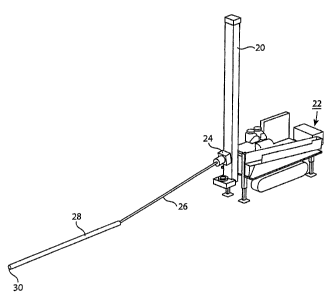
As shown in FIG. 1, the drill rig comprises an
elongated mast 20 mounted on a transporting vehicle 22, in
this case a track-driven vehicle. A top head 24 for
6
CA 02775875 2012-04-30
rotating a drill string is provided on the mast. The top
head is guided for movement lengthwise along the mast, and
movable along the mast by chains (not shown) driven by a
hydraulic motor (not shown).
The top head 24 is pivoted so that it can be tilted as
shown in FIG. 1 to a condition such that a length 26 of
drill pipe connected to the top head can be brought to a
nearly horizontal condition when the top head is moved to a
position near the lower end of the mast. When the drill
pipe is in its nearly horizontal condition, a length 28 of
well casing can be slid onto the drill pipe as shown in
FIG. 2.
The length of well casing can be drawn onto the length
of drill pipe by a cable (not shown) having a hook that
engages the end 30 of the casing. The cable extends from a
jib boom (not shown) on the mast and the casing is drawn
onto the drill pipe by operation of a winch around which
the cable is wound.
When the upper end of the length of well casing is
adjacent the top head, the top head is raised as shown in
FIG. 3, and the length of drill pipe and the surrounding
length of well casing are gradually drawn upward and into a
condition in which they are parallel to the mast as shown
in FIG. 4. At this time, the drill pipe and casing are
both aligned with an opening in a table 32, which is fixed
to the mast 20 at or near the lowermost end of the mast,
and a portion of the length 26 of drill pipe extends beyond
the lower end of the length of casing.
7
CA 02775875 2012-04-30
In the first stage of the drilling process, that is,
when the length of drill pipe 26 is to be the lowermost
length of drill pipe in the drill string and the length of
well casing 28 is to be the lowermost length of casing, a
bit will be connected to the lower end of the length of
drill pipe. The diameter of the bit should be less than
the inner diameter of the well casing so that the bit and
drill string can be withdrawn when drilling is completed,
or for replacement of the bit. Alternatively, a collapsible
bit having a diameter
larger than the internal diameter of the casing can be
used. The casing will include a drive shoe, and because
the casing will participate in drilling by enlarging the
bore hole formed by the drill bit, the drive shoe will
preferably have a circle of hardened cutting teeth
surrounding its end opening. The toothed drive shoe can be
an integral part of the lowermost length of casing, or can
be supplied as a short element for attachment to a standard
length of casing.
The table 32, as shown in FIG. 4 has a central opening
in which a casing rotator 34 is situated. The casing
rotator comprises a set of jaws which can be made to
contract by hydraulic actuators in order to grip a length
of well casing, and which can be made to rotate by a
hydraulic motor (not shown) in the table 32. The top head
and casing rotator should rotate in opposite directions.
Preferably, the top head should rotate clockwise (looking
down) to maintain a tight connection between the threads of
the top head and the uppermost length of pipe in the drill
8
CA 02775875 2012-04-30
string, and between the connecting threads of the lengths
of pipe in the drill string. The casing rotator should
rotate in the opposite direction, i.e., counterclockwise,
so that friction between the casing and the drill string
does not accidentally cause disconnection of the drill
string from the top head or disconnection of drill pipes
from one another.
The cutting bit can be attached to the exposed lower
end of the length 26 of drill pipe either before or after
the casing is moved through the casing rotator by lowering
of the top head along the mast. The drill pipe and the
length of casing are lowered through the casing rotator and
the casing is held by casing clamps (not shown) underneath
the casing rotator while the cable is disconnected from the
lower end of the casing.
After the cutting bit is in place as shown in FIG. 5,
and with the mast in its raised condition and the jaws of
the casing rotator clamped onto the length 28 of casing,
drilling and advancing of the casing can commence by
simultaneously lowering the mast, rotating the drill pipe
clockwise and rotating the casing counterclockwise. FIG. 6
shows an early stage in the drilling operation, in which
the mast is moving downward and approaching its lowermost
position.
When the mast reaches its lowermost position, the jaws
of the casing rotator are opened to release their grip on
the casing, and the mast is raised so that the jaws can
grip the length of casing at a higher position. As the
mast is raised, the top head is allowed to remain at a
9
CA 02775875 2012-04-30
fixed height so that the bit remains at the bottom of the
hole being drilled. The jaws are again closed so that the
casing rotator grips the casing, and simultaneous drilling
and advancing movement of the casing are resumed and
continued until the mast once again reaches its lowermost
position as shown in FIG. 7, whereupon the jaws are again
opened, the mast is moved upward as shown in FIG. 8, the
jaws are reengaged with the casing, and drilling and
advancing movement of the casing are continued.
When the first length of casing is advanced to a
position such that its upper end is a short distance above
the upper side of the casing rotator and the mast is at or
near its lowermost position, another length of drill pipe
and another length of casing can be attached respectively
to the first length of drill pipe and to the first length
of casing. A hydraulically operated holding fork is
extended from the rotator housing, and aligned with flats
on the drill pipe in order to grip the length of drill pipe
in the hole and allow the top head to disconnect from the
drill pipe. A new length of drill pipe is then moved into
place and attached to the top head. The attachment of the
new length of drill pipe can be carried out by moving the
top head upward on the mast and bringing the new length of
drill pipe from a storage rack or carousel into position
underneath the top head using any of various known types of
drill pipe handling equipment, for example the equipment
described in International Patent Publication No. WO
98/55728, Published December 10, 1998. The new length of
drill pipe is connected to the top head, and then connected
CA 02775875 2012-04-30
by threads to first length of drill pipe. The top head can
then be lowered while the top head and the length of drill
pipe connected to it are tilted, so that the drill pipe is
brought to a near horizontal condition as in FIG. 1. A
second length of casing can then be slid onto the drill
pipe as in FIG. 2, and the drill pipe and the surrounding
length of casing can be drawn upward as in FIG. 3 to a
condition in which they are parallel to the mast in FIG. 4
and aligned with the opening in the casing rotator. At
this time, the second length of drill pipe is attached to
the first length of drill pipe by threads, and the second
length of casing is attached to the first length of casing
either by welding, or by threads if threaded casing is
used. Simultaneous drilling and advancing movement of the
casing can then be resumed, following essentially the same
procedure as described above and depicted in FIGs. 1-8.
Additional lengths of drill pipe and casing can be
inserted in the same manner in which the second lengths of
drill pipe and casing are inserted. When the casing
reaches the desired casing depth, the space surrounding the
casing can be filled with grout, and drilling can be
continued to a desired depth below the lower end of the
casing by the addition of more lengths of drill pipe to the
drill string.
When the well reaches the desired depth, the drill
string is withdrawn. The drill bit can be withdrawn
through the casing, since its diameter is less than the
internal diameter of the casing. Alternatively various
kinds of collapsible bits, such as an "underreaming" bit,
11
CA 02775875 2012-04-30
can be used, in which case the diameter of the bit, while
drilling is taking place can be greater than the internal
diameter of the casing.
The well drilling process according to the invention
is more efficient than conventional drilling because
advancing movement of the casing and drilling are carried
out simultaneously, obviating the time-consuming withdrawal
of the drill string following the drilling of a casing bore
and prior to the introduction of the well casing. The
process can also be carried out using casings without
supporting tabs and eliminates the step of cutting the
supporting tabs off the lengths of well casing. Although
it is possible to carry out the process using conventional
drilling equipment, the use of a drill rig in which the
mast is movable lengthwise and the casing rotation table is
fixed to the mast enables the simultaneous drilling and
casing advancement to be carried out with still greater
efficiency.
25
12