Note: Descriptions are shown in the official language in which they were submitted.
CA 02775920 2012-05-03
237906
COMPONENTS AND PROCESSES OF PRODUCING COMPONENTS WITH
REGIONS HAVING DIFFERENT GRAIN STRUCTURES
BACKGROUND OF THE INVENTION
The present invention generally relates to processes for producing components
having
regions with different microstructures. More particularly, this invention is
directed to a
technique for producing components, as an example, rotating components of a
turbomachine, from preforms having different compositions. The preforms are
joined
and heat treated to yield different microstructures within regions of the
component
defined by the joined preforms.
Components within the combustor and turbine sections of a gas turbine engine
are often
formed of superalloy materials in order to achieve acceptable mechanical
properties while
at elevated temperatures resulting from the hot combustion gases produced in
the
combustor. Higher compressor exit temperatures in modern high pressure ratio
gas
turbine engines can also necessitate the use of high performance superalloys
for
compressor components, including blades, spools, disks (wheels) and other
components.
Suitable alloy compositions and microstructures for a given component are
dependent on
the particular temperatures, stresses, and other conditions to which the
component is
subjected. For example, rotating hardware such as turbine disks and compressor
spools
and disks are typically formed of alloys that must undergo carefully
controlled forging,
heat treatments, and surface treatments to produce a controlled grain
structure and
desirable mechanical properties. Notable examples of alloys used in these
applications
include gamma prime ((N) precipitation-strengthened nickel-base superalloys
containing
chromium, tungsten, molybdenum, rhenium and/or cobalt as principal elements
that
combine with nickel to form the gamma (() matrix, and contain aluminum,
titanium,
-1-
i
CA 02775920 2012-05-03
237906
tantalum, niobium, and/or vanadium as principal elements that combine with
nickel to
form the gamma prime precipitate strengthening phase, principally Ni3(AI,Ti).
Particular
examples of gamma prime nickel-base superalloys include Rend 88DT (R88DT; U.S.
Patent No. 4,957,567), Rend 95 (R95; U.S. Patent No. 3,576,681), and Rend 104
(R104;
U.S. Patent No. 6,521,175), as well as certain nickel-base superalloys
commercially
available under the trademarks Inconel , Nimonic , and Udimet . Disks and
other
critical gas turbine engine components are often forged from billets produced
by powder
metallurgy (P/M), conventional cast and wrought processing, and spraycast or
nucleated
casting forming techniques. Forging is typically performed on fine-grained
billets to
promote formability, after which a supersolvus heat treatment is often
performed to cause
uniform grain growth (coarsening) to optimize properties.
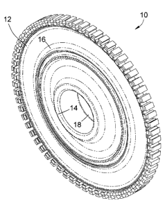
A turbine disk 10 of a type known in the art is represented in FIG. 1. The
disk 10
generally includes an outer rim 12, a central hub or bore 14, and a web 16
between the
rim 12 and bore 14. The rim 12 is configured for the attachment of turbine
blades (not
shown) in accordance with known practice. A bore hole 18 in the form of a
through-hole
is centrally located in the bore 14 for mounting the disk 10 on a shaft, and
therefore the
axis of the bore hole 18 coincides with the axis of rotation of the disk 10.
The disk 10 is
presented as a unitary forging and representative of turbine disks used in
aircraft engines,
including but not limited to high-bypass gas turbine engines such as the GE90
and
GEnx commercial engines manufactured by the General Electric Company.
The bore 14 and web 16 of the turbine disk 10 (as well as those of compressor
spools and
disks) generally have lower operating temperatures than the rim 12. It is
therefore
permissible and often desirable that the bore 14 have different properties
than the rim 12.
Depending on the particular alloy or alloys used, optimal microstructures for
the rim 12,
bore 14 and web 16 can also differ. For example, a relatively fine grain size
is often
optimal for the bore 14 and web 16 to promote tensile strength, burst
strength, and
resistance to low cycle fatigue (LCF), while a coarser grain size is often
optimal in the
rim 12 to promote creep, stress-rupture, and crack growth resistance, for
example, low
-2-
i
CA 02775920 2012-05-03
237906
dwell (hold-time) fatigue crack growth rates (DFCGR) at high temperatures. To
satisfy
these competing requirements, disks have been proposed that are formed of
multiple
alloys and/or have different microstructures within the rim and bore. For
example, U.S.
Patent Nos. 4,820,358, 5,527,020, 5,527,402 and 6,478,896 disclose dual heat
treatment
techniques capable of producing single-piece, constant-composition disks
having coarser
grains within the rim and finer grains with the bore as a result of performing
heat
treatments at different temperatures on the rim and bore, thereby obtaining
the different
grain structures and resulting different properties.
Multiple alloy disks that have been investigated typically entail the
fabrication of separate
rim and bore portions formed of different alloys. The rim and bore portions
are then
joined together, such as by welding or another metallurgical joining process.
One such
example is known as forge-enhanced bonding which, as disclosed in U.S. Patent
Nos.
5,100,050, 5,106,012 and 5,161,950, entails simultaneously forging preforms of
the rim
and bore. During the forging operation, deformation of the preforms yields the
rim and
bore as well as results in metallurgical joining of the rim and bore. Another
example is
solid-state welding processes, which include inertia welding techniques of the
types
disclosed in U.S. Patent No. 6,969,238 and U.S. Published Patent Application
Nos.
2008/0120842 and 2008/0124210. Because the different alloys may have different
solvus
temperatures such that the alloys are not conducive to a common solution heat
treatment
cycle, inertia welding has been limited to joining solution heat treated rim
and bore
portions, which are then subjected to an aging cycle after the welding
operation.
Even with the advancements outlined above, in practice current certified
commercial
flight turbine disks have only been produced as monolithic structures formed
by a single
alloy and processed to have a uniform microstructure whose grain size is
necessarily a
compromise between the creep, stress-rupture and DFCGR properties desired for
the rim
and the LCF and burst properties desired for the bore.
-3-
i
CA 02775920 2012-05-03
237906
BRIEF DESCRIPTION OF THE INVENTION
The present invention provides processes for fabricating components to have
two or more
regions with different grain structures, and components produced by such
processes.
Nonlimiting examples include rotating components of turbomachines, including
turbine
disks of gas turbine engines.
According to a first aspect of the invention, a process entails fabricating
first and second
preforms that individually correspond to first and second regions of a desired
component.
Each of the first and second preforms comprises an interface surface at which
the first
and second preforms can be joined together. The first and second preforms are
formed of
first and second precipitation-strengthened alloys, respectively, and the
first precipitation-
strengthened alloy differs from the second precipitation-strengthened alloy by
having a
higher solvus temperature or a higher grain refiner content of at least one
grain-refining
element. The first and second preforms are joined together to form an article
comprising
first and second portions formed by the first and second preforms,
respectively, and
corresponding to the first and second regions of the component, respectively,
and so that
the interface surfaces of the first and second preforms form a solid-state
joint located
between the first and second portions of the article. A supersolvus heat
treatment is then
performed on the article so that greater grain growth occurs in the second
portion than in
the first portion.
According to a particular aspect of the invention, if the first precipitation-
strengthened
alloy has a higher solvus temperature than the second precipitation-
strengthened alloy,
then the supersolvus heat treatment heats the article to a temperature above
the solvus
temperature of the second precipitation-strengthened alloy of the second
portion but not
above the solvus temperature of the first precipitation-strengthened alloy of
the first
portion. According to another particular aspect of the invention, if the first
precipitation-
strengthened alloy has a higher grain refiner content than the second
precipitation-
strengthened alloy, then the supersolvus heat treatment heats the article to a
temperature
-4-
I
CA 02775920 2012-05-03
237906
above the solvus temperatures of the first and second precipitation-
strengthened alloys of
the first and second portions.
According to another aspect of the invention, a process of fabricating a
turbine disk of a
gas turbine engine entails fabricating first and second preforms individually
corresponding to a bore and a rim of the disk. Each of the first and second
preforms
comprises an interface surface at which the first and second preforms can be
joined
together. The first and second preforms are formed of first and second gamma
prime-
strengthened nickel-base superalloys, respectively, and the first gamma prime-
strengthened nickel-base superalloy differs from the second gamma prime-
strengthened
nickel-base superalloy by having a higher gamma-prime solvus temperature or a
higher
grain refiner content of at least one grain-refining element. The first and
second preforms
are joined together to form an article comprising first and second portions
formed by the
first and second preforms, respectively, and corresponding to the rim and the
bore of the
disk, respectively. In addition, the interface surfaces of the first and
second preforms
form a solid-state joint located between the first and second portions of the
article and
corresponding to a web of the disk interconnecting the rim and the bore. A
supersolvus
heat treatment is then performed on the article so that greater grain growth
occurs in the
second portion than in the first portion, the bore has an average grain size
of ASTM 8 or
smaller, and the rim to have an average grain size of ASTM 7 or larger. If the
first
gamma prime-strengthened nickel-base superalloy has a higher gamma-prime
solvus
temperature than the second gamma prime-strengthened nickel-base superalloy,
then the
supersolvus heat treatment heats the article to a temperature above the gamma-
prime
solvus temperature of the second gamma prime-strengthened nickel-base
superalloy but
not above the gamma-prime solvus temperature of the first gamma prime-
strengthened
nickel-base superalloy. If the first gamma prime-strengthened nickel-base
superalloy has
a higher grain refiner content than the second gamma prime-strengthened nickel-
base
superalloy, then the supersolvus heat treatment heats the article to a
temperature above
the gamma-prime solvus temperatures of the first and second gamma prime-
strengthened
nickel-base superalloys.
-5-
i
CA 02775920 2012-05-03
237906
Other aspects of the invention include components formed by one of the
processes
comprising the steps described above.
A technical effect of the invention is the ability to produce a component
having two or
more regions with different properties, including different grains sizes so
that the
different regions of the component can have grain sizes that promote different
properties.
In terms of a turbine disk, the process can produce a disk to have finer
grains in the bore
and coarser grains in the rim, enabling the properties of the rim and bore to
be tailored or
otherwise better adapted for the different operating conditions of the rim and
bore.
Another effect of the invention is the ability to produce the rim and bore
from different
alloys having significantly different solvus temperatures and/or properties,
or from alloys
that differ only in the amounts of grain-refining elements they contain. The
process of
this invention can potentially be applied to a wide variety of alloys, heat
treatments, and
forging conditions to achieve different grain sizes and structures within
different regions
of a component.
Other aspects and advantages of this invention will be better appreciated from
the
following detailed description.
BRIEF DESCRIPTION OF THE DRAWINGS
FIG. I is a perspective view of a turbine disk of a type used in gas turbine
engines.
FIG. 2 represents the fabrication of a dual-alloy turbine disk by inertia
welding a rim
preform to a bore preform, and FIG. 3 represents the resulting turbine disk
profile in
accordance with an embodiment of the present invention.
FIG. 4 represents rim and bore preforms for fabricating a dual-alloy turbine
disk, FIG. 5
is a cross-sectional view representing a forge-enhanced bonding technique
performed on
the preforms of FIG. 4 to yield a forging, and FIG. 6 represents a turbine
disk profile
produced from the forging of FIG. 5 in accordance with another embodiment of
the
present invention.
-6-
I
CA 02775920 2012-05-03
237906
FIG. 7 is a microphotograph of a dual-alloy disk produced from two alloys
having
different solvus temperatures, and following a solution heat treatment at a
temperature
above only one of the two solvus temperatures in accordance with a particular
aspect of
the present invention.
FIG. 8 is a microphotograph of a dual-alloy disk produced from two alloys
differing only
in their carbon contents, having essentially the same solvus temperature, and
following a
solution heat treatment at a temperature above their solvus temperature in
accordance
with another particular aspect of the present invention.
DETAILED DESCRIPTION OF THE INVENTION
The present invention will be described with reference to rotating hardware of
the type
used in turbomachines, and particularly turbine and compressor disks and
compressor
spools of high-bypass gas turbine engines. However, though it should be
understood that
the teachings and benefits of the invention are not limited to such hardware,
and instead
can be adapted and applied to hardware used in a wide range of applications.
For
convenience, the invention will be described in particular reference to the
turbine disk 10
represented FIG. 1, though it should be understood that the teachings and
benefits of the
invention are not limited to this particular disk 10.
FIG. 2 represents a step involved in fabricating the disk 10 using an inertia
welding
technique, and FIGS. 4 and 5 represent steps involved in fabricating the disk
10 using a
forge-enhanced bonding technique. Both processes entail preparing a separate
rim
preform 22 or 42 and bore preform 24 or 44, which then undergo a joining
process, such
as the inertia welding technique of FIG. 2 to yield a welded profile 30,
represented in
FIG. 3 as having rim, bore and web portions 32, 34 and 36, respectively, and a
solid-state
joint 38, or undergo the forge-enhanced bonding technique of FIGS. 4 and 5 to
yield a
forged profile 50, represented in FIG. 6 as having rim, bore and web portions
52, 54 and
56, respectively, and a solid-state joint 58. The processes and profiles 30
and 50
represented in FIGS. 2 through 6 are intended to be nonlimiting, since it is
foreseeable
-7-
CA 02775920 2012-05-03
237906
that other techniques could be employed to metallurgically join the preforms
22, 44, 32
and 44, as well as combinations of various techniques. In any case, the rim
preform
22/42 is formed from an alloy that is different than the alloy from which the
bore preform
24/44 is formed. The alloys used to form the preforms 22, 24, 42 and 44 are
preferably
strengthened with a precipitation phase that can be solutioned during
processing of the
alloys. In the context of forming the turbine disk 10, preferred alloys for
the preforms 22,
24, 42 and 44 are gamma prime precipitation-strengthened nickel-base alloys.
In all
cases, the alloys for the preforms 22, 24, 42 and 44 are chosen on the basis
of the
operating conditions to which the final product will be subjected. As such,
alloys for the
rim preforms 22 and 42 are chosen on the basis of the operating conditions of
the rim 12
and alloys for the bore preforms 24 and 44 are chosen on the basis of the
operating
conditions of the bore 14 when the disk 10 is installed in a turbomachine,
such as a gas
turbine engine. Additionally the bore and rim alloys may be chosen in part
based on their
responses to the processes used to manufacture the preforms 22, 24, 42 and 44,
or based
on the characteristics of their responses to joining processes and the
mechanical behavior
of their respective joints 38 and 58. Nonlimiting examples of suitable
materials include
the aforementioned gamma prime nickel-base superalloys R88DT, R95 and R104, as
well
as certain nickel-base superalloys commercially available under the trademarks
Inconel ,
Nimonic , and Udimet .
Because the resulting rim 12 and bore 14 are produced from different alloys,
the disk 10
can be termed a multi-alloy component whose rim 12 and bore 14 can be formed
of
materials better tailored for different operating conditions to which the rim
12 and bore
14 are subjected. Also, as will be noted below, the rim preforms 22 and 42 and
bore
preforms 24 and 44 can be produced from alloys that are sufficiently different
to enable
the resulting profiles 30 and 50 to respond to a mono-temperature solution
heat treatment
with different grain growth responses. However, it is within the scope of the
invention
that different solution heat treatments could be performed on regions of the
profiles 30
and 50 corresponding to the rim 12 and bore 14 of the disk 10. It is also
within the scope
-8-
i
CA 02775920 2012-05-03
237906
of the invention that preforms could be produced for additional regions of the
disk 10, for
example, the web 16, to achieve desired microstructures between the bore 14
and rim 12.
With reference to the inertia welding technique of FIGS. 2 and 3, FIG. 2
represents
portions of the rim preform 22 and bore preform 24 in cross-section. It should
be
appreciated that, because of the axisymmetric configuration of the disk 10,
there are
diametrically opposite portions of preforms 22 and 24 that are not shown in
FIG. 2. The
preforms 22 and 24 can be produced by a variety of known processes, including
billets
produced by powder metallurgy (P/M), conventional cast and wrought processing,
and
spraycast or nucleated casting forming techniques. The preforms 22 and 24
preferably
have an average grain size of about ASTM 6 to about 9, which is a suitable
range for
providing acceptable LCF properties in the bore 14 while allowing for grain
growth in the
rim 12 that is capable of promoting creep properties. FIG. 2 illustrates that
the rim and
bore preforms 22 and 24 can be forged or otherwise fabricated prior to inertia
welding to
produce the disk profile 30 of FIG. 3, which closely corresponds to the
desired
geometries of the rim 12, bore 14 and web 16 in the final disk 10.
The preforms 22 and 24 are shown in FIG. 2 as having two machined interface
surfaces
28 at which joining occurs by inertia welding. The surfaces 28 are located
within regions
26 of the preforms 22 and 24 corresponding to the web 16 of the disk 10, such
that the
resulting weld joint (38 in FIG. 3) will be located in the web 16 of the disk
10. The
interface surfaces 28 are further represented as being oriented at an angle to
the axis 20 of
the eventual disk 10, providing a contact (draft) angle that facilitates
assembling and
mating of the annular-shaped rim preform 22 within the bore preform 24, as
indicated by
the arrows in FIG. 2. Consequently, the resulting weld joint 38 shown in FIG.
3 is also
inclined at the same angle. However, it is foreseeable that the interface
surfaces 28 of the
rim and bore preforms 22 and 24 could vary from that illustrated and, in fact,
be parallel
to the disk axis 20. To further facilitate assembly and contact between the
preforms 22
and 24, the surfaces 28 are preferably conformably shaped so that they readily
slide into
contact with each other.
-9-
I
CA 02775920 2012-05-03
237906
The inertia welding process represented by FIG. 2 is a solid-state welding
technique
accomplished by rotating the rim preform 22 and/or bore preform 24 about the
disk axis
20. As a matter of convenience, the rim preform 22 may be held stationary and
the bore
preform 24 rotated. While relative rotation is occurring, the rim and bore
preforms 22
and 24 are moved together parallel to the axis 20 until their interface
surfaces 28 come in
contact. As relative rotation continues, the contacting surfaces 28 generate
frictional
heating, and increasing the application of force in the axial direction
increases the
temperatures of the regions underlying the surfaces 28 of the rim and bore
preforms 22
and 24 to a temperature approaching the incipient melting temperatures of the
materials
from which the preforms 22 and 24 are made. The axial force, relative
rotational speeds
and input rotational energy at initiation of welding, and required relative
displacements
necessary to inertia weld the preforms 22 and 24 will vary, depending on the
size, mass
and materials of the preforms 22 and 24 and the surface area of their
interface surfaces
28. The preforms 22 and 24 are held in contact under these conditions for a
period of
time sufficient to cause them to bond together along their contacting surfaces
28 as the
rotational speed decays to zero, forming the solid-state weld joint 38 that
contains fine-
grained material as a result of the temperatures sustained during inertia
welding. FIG. 3
represents the resulting profile 30 as having a rim portion 32, bore portion
34 and web
portion 36 that closely correspond to the desired geometries of the rim 12,
bore 14 and
web 16, respectively, in the final disk 10.
With reference to the forge-enhanced bonding technique of FIGS. 4 through 6,
FIG. 4
represents portions of the rim preform 42 and bore preform 44 in cross-
section. Again, it
should be appreciated that, because of the axisymmetric configuration of the
disk 10,
there are diametrically opposite portions of the preforms 42 and 44 that are
not shown in
FIG. 4. The preforms 42 and 44 can be also produced by processes of the type
identified
for the preforms 22 and 34 of FIG. 2. For illustrative purposes, FIG. 4
depicts the
outlines of the rim portion 52 and bore portion 54 of the resulting profile 50
of FIG. 6,
which closely corresponds to the desired geometries of the rim 12, bore 14 and
web 16 in
the final disk 10.
-10-
i
CA 02775920 2012-05-03
237906
The preforms 42 and 44 are shown in FIG. 4 as having two machined interface
surfaces
48 located within regions 46 of the preforms 42 and 44 corresponding to the
web 16 of
the disk 10, such that the resulting solid-state joint (58 in FIG. 5) will be
located in the
web 16 of the disk 10. The interface surfaces 48 are further represented as
being oriented
at an angle to the axis 20 of the eventual disk 10, with the result that the
joint 58 is also
inclined at the same angle. However, it is foreseeable that the interface
surfaces 48 of the
rim and bore preforms 42 and 44 could be parallel to the disk axis 20. To
further facilitate
assembly and contact between the preforms 42 and 44, the surfaces 48 are
preferably
conformably shaped to promote uniform contact therebetween.
The preforms 42 and 44 are placed in dies 62 and 64 of a forge press to yield
the forging
40 represented in FIG. 5. Suitable forging conditions will depend on the
particular
materials and sizes of the preforms 42 and 44 and are generally within the
knowledge and
capability of those skilled in the art, particularly in view of the teachings
of U.S. Patent
Nos. 5,100,050, 5,106,012 and 5,161,950, and therefore will not be discussed
in any
detail here. The cavities 66 and 68 of the dies 62 and 64 substantially define
the shape of
the profile 50 everywhere except at the interface surfaces 48 and, therefore,
the joint 58
within the forging 40. FIG. 5 represents the result of the forging operation,
during which
material flows from the interface surfaces 48 into cavities or vents 70 and 72
of the dies
62 and 64. The vents 70 and 72 are represented as coaxial but having different
diameters,
so that the vents 70 and 72 are not axially aligned in the axial direction of
the disk axis 20
but instead are radially offset from each other. The offset is selected so
that the material
in the vicinity of the interface surfaces 48 of the preforms 42 and 44 will
face one of the
vents 70 and 72 when forging is initiated, and during forging will be
displaced or
expelled into the vents 70 and 72. A very large degree of metal flow and grain
distortion
intentionally occurs during forging within the material in the vicinity of the
interface
surfaces 48 of the preforms 42 and 44. Using a single or multiple strokes
during the
forging operation, this distortion is purged from the forging 40 into the
vents 70 and 72,
resulting in the creation of annular flanges 74 and 76. The flanges 74 and 76
are then
-11-
CA 02775920 2012-05-03
237906
removed during final machining of the forging 40 to produce the desired
profile 50
shown in FIG. 6.
It is well known in the art that many nickel-base superalloys have preferred
strain rate
regimes to achieve desired supersolvus grain growth behavior. The forge-
enhanced
bonding technique described above (as well as other forging techniques) offers
the
necessary control capabilities to achieve these regimes in the region of the
joint 58 to
achieve a preferred grain growth. Adjustment of the geometries of the preforms
42 and
44 and their respective interface surfaces 48, along with forge process
control, may be
used to achieve the desired strain and strain rate profiles local to the joint
58 as well as
throughout the entire forging 40. In one example, the method of joining could
include an
initial inertia welding step (for example, of the type described in reference
to FIGS. 2 and
3). For certain alloys, the strain and strain rate patterns created by inertia
welding would
not achieve the desired regimes for preferred grain growth. The initial
joining step could
then be followed by a forging operation so that sufficient strain is induced
in the preferred
strain rate regime to dominate subsequent supersolvus grain growth behavior.
The
forging operation may be a forge-enhanced bonding technique similar to that
described in
reference to FIGS. 4 through 6, but with the oppositely-disposed edges of the
weld joint
38 facing the vents 70 and 72 when forging is initiated so that portions of
the weld joint
38 are displaced or expelled into the vents 70 and 72 during forging.
As previously discussed, a preferred aspect of the invention is to produce the
disk 10 so
that its rim 12 and bore 14 are formed of different compositions, and then
heat treating
the disk 10 to obtain a finer structure in the bore 14 and a coarser structure
in the rim 12.
In investigations leading up to the present invention, two approaches were
evaluated.
A first of the approaches involved producing a profile (30 or 50) whose rim
and bore
portions (22/42 and 24/44) are separately formed and joined together, for
example, using
the inertia welding or forge-enhanced bonding techniques described above. The
bore
portion 24/44 is composed of a precipitation-strengthened alloy having a
solvus
temperature significantly higher than that of the rim portion 22/42. For
example, the rim
-12-
CA 02775920 2012-05-03
237906
and bore portions 22/42 and 24/44 are formed of two gamma prime precipitation-
strengthened nickel-base superalloys, and the gamma prime precipitation-
strengthened
nickel-base superalloy of the bore portion 24/44 has a gamma prime solvus
temperature
at least 10 C higher and more preferably at least 25 C higher than the gamma
prime
precipitation-strengthened nickel-base superalloy of the rim portion 22/42.
The profile
30/50 is then heat treated at a solution heat treat temperature higher than
solvus
temperature of the alloy within the rim portion 22/42, but lower than the
solvus
temperature of alloy within the bore portion 24/44. This creates a disk 10
having a
subsolvus heat treated bore 14 having a fine-grained microstructure that
promotes its
tensile strength, burst strength, and LCF resistance, and a supersolvus heat
treated rim 12
having a coarser grain size that promotes its creep, stress-rupture, and crack
growth
resistance, for example, DFCGR.
The second approach involved producing a profile (30 or 50) whose rim and bore
portions (22/42 and 24/44) are again separately formed and joined together,
for example,
using the inertia welding or forge-enhanced bonding techniques described
above. As
with the first approach, the rim and bore portions 22/42 and 24/44 are
composed of
precipitation-strengthened alloys, for example, two gamma prime precipitation-
strengthened nickel-base superalloys. However, with the second approach the
two alloys
are not required to have different solvus temperatures, and instead they may
have the
same solvus temperature or their solvus temperatures may be within 25 C of
each other.
Instead, the rim and bore portions 22/42 and 24/44 may have substantially the
same
composition, but the alloy for the bore portions 24/44 is alloyed to contain a
greater
amount of one or more minor elements capable of having a grain-refinement
effect. Two
notable examples are carbon or boron, though the use of other grain refiners
is also
foreseeable. As particular but nonlimiting examples, the alloy for the bore
portion 24/44
may contain at least 0.1 weight percent of carbon, while the alloy for the rim
portion
22/42 may contain less than 0.06 weight percent of carbon. Because the alloys
for the
rim and bore portions 22/42 and 24/44 are only required to differ in terms of
their grain
refiner contents, the alloy for the bore portion 24/44 can be produced by
modifying the
-13-
CA 02775920 2012-05-03
237906
alloy of the rim portion 22/42 to contain an additional quantity of one or
more grain-
refining elements. It is also within the scope of the invention to process the
bore portion
24/44 so that one or more limited portions thereof contain a greater amount of
one or
more minor elements so that the desired grain-refinement effect occurs within
the
portion(s) containing the higher levels of grain refiner(s). For example,
grain refiners
could be locally added by a surface treatment such as carburizing, ion
implantation, etc.,
performed prior to heat treatment. As a result, only the surface portion(s)
receiving the
surface treatment and surface regions beneath the surface portion(s) would
contain the
higher grain refiner content.
The profile 30/50 is then heat treated at a solution heat treat temperature
higher than the
solvus temperature(s) of the alloys within the rim portion 22/42 and bore
portion 24/44.
Due to the grain refinement effect of the grain refining element(s), whose
higher content
in the bore portion 24/44 restricts grain growth within the bore portion 24/44
more than
within the rim portion 22/42, the resulting disk 10 has a supersolvus heat
treated rim 12
having coarse-grained microstructure that promotes its creep, stress-rupture,
and crack
growth resistance (for example, DFCGR) and a supersolvus heat treated bore 14
having a
finer grain size that promotes its tensile strength, burst strength, and LCF
resistance.
Because a mono-temperature solution heat treatment can be used (in other
words, the
entire profile 30/50 is heated to a substantially uniform temperature), it is
foreseeable that
the solution heat treatment could be performed prior to joining the rim and
bore portions
22/42 and 24/44, instead of after the joining operation.
In a first of the investigations, a disk was produced to have its rim formed
of R88DT
(U.S. Patent No. 4,957,567) and its bore formed of R95 (U.S. Patent No.
3,576,681). The
gamma prime solvus temperature of R88DT is estimated to be about 1120 C and
the
gamma prime solvus temperature of R95 is estimated to be about 1175 C. The
disk was
produced by forge-enhanced bonding as described above in reference to FIGS. 4
through
6. A mono-temperature heat treatment was performed at about 2100EF (about
I150EC)
for about one hour, which was above the solvus temperature (supersolvus) of
the R88DT
-14-
i
CA 02775920 2012-05-03
237906
alloy used to form the rim portion, but below the solvus temperature
(subsolvus) of the
R95 alloy used to form the bore portion. The result was a fine-grained bore
having an
average grain size of ASTM 10 and finer, and a coarser-grained rim portion
having an
average grain size of ASTM 7 and coarser. These grain sizes are advantageous
in that the
resulting bore had high yield strength for resistance to burst, whereas the
rim would be
resistant to crack growth rates. FIG. 7 is a microphotograph showing the
microstructure
of the dual-alloy disk, with the microstructure of R88DT seen on the left and
the
microstructure of R95 seen on the right in the image.
In a second investigation, two disks were produced to have rims and bores
formed of
alloys based on R104 (U.S. Patent No. 6,521,175). The carbon content of the
rim alloy
was within the typical range of about 0.02-0.08% for the R104 alloy, whereas
the R104
alloy of the bores was modified to have the higher carbon content. The disks
were
produced by inertia welding as described above in reference to FIGS. 2 and 3.
One of the
disks was produced by heat treating extruded preforms of the rim and bore
followed by
inertia welding, while the second disk was produced by inertia welding
extruded
preforms of the rim and bore followed by a heat treatment. In each case, the
heat
treatment was performed at about 2140 F (about 1170 C) for about one hour,
which was
above the essentially identical solvus temperatures (supersolvus) of the R104
alloys used
to form the rim and bore portions.
The microstructures within both welds were characterized by a noticeably finer
grain
structure on the higher-carbon bore side of the weld joints. The results were
fine-grained
bores and coarser-grained rims. A notable difference between the two weld
joints was
that the specimen produced from the preforms that were solution heat treated
prior to
welding experienced grain size refinement along the weld bond line, whereas
the weld
joint of the specimen produced by solution heat treating the profile after
welding was
characterized by grain growth along the weld bond line. Neither weld joint
exhibited
critical grain growth, which was believed to be attributable in part to the
critical grain
growth resistance exhibited by the R104 alloy and in particular the carbon
content of the
-15-
i
CA 02775920 2012-05-03
237906
higher-carbon R104 alloy of the bore, which was concluded to have formed
carbides that
provided a grain boundary pinning effect. FIG. 8 is a microphotograph showing
the
microstructure of the dual-alloy disk, with the microstructure of the higher-
carbon R104
alloy visible in the upper half of the image and the microstructure of the
lower-carbon
R104 alloy visible in the lower half in the image.
From the above, it can be appreciated that the alloys chosen for the rim 12
and bore 14
can be optimized via their major element chemistry composition to influence
gamma-
prime solvus composition and content, and their minor element chemistry
composition to
influence degree of grain refinement. In effect, the rim 12 and bore 14 can be
produced
from different alloys that enable or cause the final article to respond to
controlled mono-
temperature heat treatments to achieve different grain growth responses in the
rim 12 and
bore 14. However, it is also foreseeable that a dual heat treatment could be
performed on
the profiles 30 and 50, in which case the rim portion 32/52 and bore portion
34/54 are
subjected to different supersolvus and/or different stabilization/aging
temperatures to
optimize grain size and properties within the rim 12 and bore 14. Examples of
dual heat
treatment techniques are disclosed in U.S. Patent No. 4,820,358, 5,527,020,
5,527,402
and 6,478,896.
While the invention has been described in terms of a specific embodiment, it
is apparent
that other forms could be adopted by one skilled in the art. Therefore, the
scope of the
invention is to be limited only by the following claims.
-16-
i