Note: Descriptions are shown in the official language in which they were submitted.
CA 02775946 2012-03-29
Guide wire
Technical field
The invention relates to a guide wire for a catheter,
designed to introduce and/or remove fluids in human
and/or animal hollow organs, in particular in blood
vessels, comprising an elongate hollow shaft with a
lumen for delivering and/or withdrawing the fluid, and
an insertion aid in the form of a flexible wire coil
attached coaxially to a distal end of the hollow shaft,
with a guide-wire tip arranged at a distal end, a core
wire being arranged in the lumen of the hollow shaft in
order to control a flexibility of the guide wire, which
core wire extends out of the lumen in a longitudinal
direction and right through the wire coil to the guide-
wire tip. The invention further relates to a method for
the diagnostic and/or therapeutic treatment of vessels
and/or tumors and to a use of a guide wire for
diagnostic and/or therapeutic purposes on the human
and/or animal body.
Prior art
Guide wires usually serve as aids for inserting
catheters into human and/or animal hollow organs. The
guide wires are pushed into the hollow organ before the
insertion of the catheter and are positioned at a
desired location. To do this, the guide wires have to
be sufficiently flexible and thin at the distal end,
for example in order also to follow narrow and strongly
curved vessel profiles. At the same time, however, the
guide wires must also have sufficient stiffness to
ensure that they can be pushed forward from the
direction of the proximal end.
CA 02775946 2012-03-29
- 2 -
Hollow guide wires are also known which, for example,
are used to introduce and/or remove liquid and act as
pressure measurement probes in a hollow organ. In the
proximal part, guide wires of this kind have, for
example, a hollow steel tube which, at the distal end,
has a relatively flexible helical spring with a guide-
wire tip. In order to control the stiffness of the
guide wire, a core wire, for example, is mounted on the
distal end of the steel tube, which core wire extends
through the helical spring as far as the guide-wire
tip. In the area of the proximal end of the helical
spring, the core wire is also welded to the latter all
the way round, in order to permit a defined sliding of
the guide wire.
In order to deliver and/or withdraw a fluid through the
guide wire, one or more lateral openings are formed in
the steel tube behind the wire coil. In this way, a
fluid can be delivered through the hollow guide wire
and the lateral openings into the hollow organ, or a
fluid is removed from the hollow organ through the
lateral openings and the guide wire. A hollow guide
wire, which is used as a pressure measurement probe, is
described, for example, in WO 97/32518 (Scimed Life
Systems Inc .) .
A deflectable guide wire for infusions is known from US
2007 213 689 Al (Johnson & Johnson) . The steerable end
is formed by a wire coil. To be able to direct the
infusion liquid into the area of the wire coil, the
guide wire accommodates an independent infusion tube,
which extends from the proximal end into the area of
the wire coil, where the therapeutic liquid can flow
out of the guide wire through the gaps between the
windings of the wire coil. The wire coil is
accommodated between an inner and an outer jacket made
of plastic. A disadvantage here is that a separate
infusion tube has to be accommodated in the guide wire
CA 02775946 2012-03-29
3 -
and that the release of the liquid in the coil area
cannot be controlled.
WO 97/11735 Al (Interventional Innovations) discloses a
guide wire whose distal part has a smaller diameter
than the proximal part. An open wire coil made of
tungsten or platinum is secured on the distal part of
the guide wire, in order to make the distal tip of the
guide wire softer for protecting tissue. A rod element
protruding from a distal end of the hollow wire and
into the wire coil is provided with a groove for the
liquid exchange. The open wire coil is not suitable for
the transport of liquid, such that the liquid can only
be released exactly where the groove emerges from the
guide wire.
US 5 322 508 A (Cordis Corporation) discloses another
guide wire having a transport system for liquid. A wire
coil is wound onto a core wire, and a plastic jacket is
applied to the outside of the wire coil. The liquid is
advanced in a helical line configuration in the
interstices of the coil. The liquid can emerge at the
end of the plastic enclosure. A disadvantage is that
guiding the liquid in a helical line configuration
results in a very long and narrow channel with
correspondingly high flow resistance.
US 5 211 636 A (Lake Region Manufacturing) proposes a
guide wire composed of an outer and an inner helical
spring, in the center of which a core wire is arranged.
The outer helical spring has the structure of a ribbon
shaped as a helical line and made up of four coil wires
extending parallel to one another and connected to one
another. The inner helical spring is formed by a single
wire, with a spacing present between adjacent windings.
The coils are routed in opposite directions, such that
the guide wire is able to transmit a torque. The main
part of the helical spring is wound tightly in order to
CA 02775946 2012-03-29
4 -
achieve maximum control of the guide wire. The helical
wire is wound with spacings at the distal end, and the
spacings between the windings serve as infusion
openings. A membrane is provided on the inner face of
the inner coil or between inner coil and outer coil,
such that the central lumen, in which the core wire is
also located, can be used as a channel for the infusion
liquid.
However, the currently known hollow guide wires for
delivering and/or withdrawing a fluid are not
completely satisfactory.
There is therefore still a need for an improved and
easily insertable guide wire for delivering and/or
withdrawing a fluid.
Disclosure of the invention
The object of the invention is to make available an
easily insertable guide wire which belongs to the
technical field mentioned at the outset and which
permits more precise introduction and/or removal of
fluids in human and/or animal hollow organs.
The object is achieved by the features defined in claim
1. According to the invention, a distal inner area of
the wire coil, adjacent to the guide-wire tip in a
proximal direction, communicates with the lumen of the
hollow shaft via a fluid channel formed alongside the
core wire and also has at least one outwardly open
through-opening for the fluid that is to be introduced
and/or removed.
In this context, a wire coil is to be understood in
particular as a hollow cylindrical structure which is
formed by a wire wound helically about a longitudinal
axis. The wire coil is formed in particular from a
CA 02775946 2012-03-29
- 5 -
metal wire, e.g. of platinum. However, the wire of the
wire coil does not necessarily have to be made of
metal. It is also conceivable in principle to provide a
wire made of plastic.
The core wire is made in particular from metal, for
example from steel. In principle, however, other
materials can also be used for the core wire, e.g.
high-strength plastics and/or composite materials.
By means of the through-opening being arranged
according to the invention in a distal inner area of
the wire coil adjacent to the guide-wire tip, the
through-opening lies in an area in direct proximity to
the guide-wire tip. In combination with the fluid
channel between the distal inner area and the lumen of
the hollow shaft, a fluid can thus be introduced from
the guide wire into a hollow organ directly in an area
of the guide-wire tip and/or removed therefrom. The at
least one opening of the distal inner area of the wire
coil is preferably directly adjacent, in the proximal
direction, to the guide-wire tip.
Since the position of the guide-wire tip in a hollow
organ can generally be determined relatively precisely,
e.g. by known imaging methods, for example using X-
rays, the proximity of the at least one through-opening
to the guide-wire tip also means that the position of
the at least one through-opening can be determined very
exactly. Particularly in comparison with known guide
wires in which the through-openings are arranged in the
proximal direction behind the wire coil, the position
of the through-opening in the guide wire according to
the invention can therefore be determined more
precisely.
Because of the core wire extending from the lumen
through the wire coil as far as the guide-wire tip, the
CA 02775946 2012-03-29
6 -
elasticity of the guide wire in its distal areas can
also be adjusted very exactly, which additionally
improves the insertability and controllability of the
guide wire in a hollow organ. It is specifically
possible, for example, for abrupt changes of elasticity
in the area of the transition between hollow shaft and
wire coil to be compensated by the core wire, which,
for example, counteracts a kinking of the guide wire
during insertion. Likewise, the elasticity of the
usually superelastic wire coil can be reduced by the
core wire and adapted to the specific requirements. It
is thus possible, in particular, to use wire coils with
especially small wire diameters, which in particular
saves space. The guide wire or the guide-wire tip can
thus be moved or maneuvered in a more targeted and more
precise manner to a desired location in the hollow
organ. As has been shown, in combination with the
inventive arrangement of the through-opening, it is
thus possible to increase to a surprising extent the
precision with which fluids are introduced and/or
removed in human and/or animal hollow organs.
Moreover, the solution according to the invention
permits a space-saving and compact construction, since
the fluid channel between the lumen and the distal
inner area of the wire coil can extend entirely within
the lumen and the wire coil. A free space is preferably
formed alongside the core wire in the lumen of the
hollow shaft and/or in the inner area of the wire coil,
said free space functioning as a fluid channel. In a
particularly advantageous embodiment, the hollow shaft
has, at its distal end, a front opening which
communicates with a front opening at the proximal end
of the wire coil. The cross-sectional surface areas of
the two front openings on the hollow shaft and on the
wire coil are advantageously larger than a cross-
sectional surface area of the core wire in this area.
CA 02775946 2012-03-29
- 7 -
In this way, a free space permitting passage of the
fluid remains alongside the core wire.
In a construction of this kind, the guide wires
according to the invention can be designed with a
cross-sectional surface area that is substantially
constant along their entire length or that decreases
continuously toward the guide-wire tip, which in turn
improves the insertability of the guide wire.
The distal end of the hollow shaft and the proximal end
of the wire coil are, for example, welded and/or
adhesively bonded to each other. In particular, a
proximal end of the wire coil can bear with its face on
a distal end of the hollow shaft. However, it is also
possible to push the proximal end of the wire coil onto
the distal end of the hollow shaft, such that the
proximal end of the wire coil surrounds the distal end
of the hollow shaft. An arrangement in which the
proximal end of the wire coil is pushed into the distal
end of the hollow shaft is also advantageous. In this
case, the distal end of the hollow shaft surrounds the
proximal end of the wire coil.
Overall, the guide wires according to the invention are
easily insertable into human and/or animal hollow
organs and also permit highly precise and targeted
introduction and/or removal of fluids at defined
locations in human and/or animal hollow organs.
Preferably, a fluid-permeable connection between wire
coil and core wire is present in an area of a proximal
end of the wire coil, such that the wire coil is
mechanically fixed relative to the core wire, and the
distal inner area of the wire coil communicates with a
proximal inner area of the wire coil lying proximally
from the fluid-permeable connection. In this way, in
particular, a still more precise sliding of the guide
CA 02775946 2012-03-29
- 8 -
wire in a hollow organ is possible, since compressions
and/or expansions of the wire coil in the longitudinal
direction are almost completely prevented, without
thereby substantially impairing the transverse
flexibility of the guide wire. Since the connection
between wire coil and core wire is in particular fluid-
permeable, the proximal inner area lying proximally
from the connection still nevertheless communicates
with the distal inner area of the wire coil lying
distally from the connection. In this way, even with a
stable mechanical connection between core wire and wire
coil, it is possible to easily obtain a fluid channel
extending in the longitudinal direction through the
wire coil.
If necessary, e.g. in the case of very long wire coils,
it is possible for several fluid-permeable connections
to be arranged, spaced apart from one another in the
longitudinal direction, between wire coil and core
wire. However, it is also conceivable in principle to
do without a fluid-permeable connection. However, in
the case of very narrow hollow organs, which generate a
high degree of resistance upon movement of the guide
wire, this may sometimes be disadvantageous, since
there is the possibility of the wire coil being
strongly compressed and/or expanded during the
movement.
In particular, the fluid-permeable connection is
present as an integrally bonded connection which is
designed asymmetrically and/or to one side with respect
to a longitudinal center axis of the wire coil, in
particular a soldered connection, between wire coil and
core wire. This has the effect that, in the area of the
fluid-permeable connection, a channel-like passage
lying to the side of the core wire remains free for the
fluid that is to be delivered and/or withdrawn.
Moreover, in a fluid-permeable connection designed in
CA 02775946 2012-03-29
9 -
this way, no additional elements are required, which
particularly reduces the amount of space needed and
permits a correspondingly more compact construction of
the guide wire.
The integrally bonded connection is in particular a
soldered connection. However, it is also possible to
provide an adhesive connection and/or a welded
connection. In particular, several separate connection
webs can be present, e.g. composed of a solder and/or
an adhesive, which extend for example in a radial
direction between core wire and wire coil. The
connection webs then form a fluid-permeable connection,
since the free spaces between the connection webs form
a passage for fluid.
In another preferred embodiment, the fluid-permeable
connection is designed as an integrally bonded
connection, in particular as a soldered connection,
wherein a tube extending parallel to the core wire and
embedded in the integrally bonded connection is present
as a channel-like passage for the fluid that is to be
delivered and/or withdrawn. The integrally bonded
connection can be designed, for example, as a soldered
connection and/or adhesive connection. Because of the
tube, the fluid-permeable connection has, on the one
hand, a relatively precisely defined through-opening.
On the other hand, it has been shown that a tube can be
relatively easily embedded in the integrally bonded
connection, which simplifies the production of the
guide wire. In this case, the core wire, with the tube
arranged alongside it, can be connected all the way
round to the wire coil in an integrally bonded manner,
which is usually easier than connecting the core wire
on one side to the wire coil. Moreover, a more stable
connection between core wire and wire coil is formed.
CA 02775946 2012-03-29
- 10 -
The core wire is advantageously fixed in the lumen at a
distance in the proximal direction from the proximal
end of the wire coil and, in particular, is arranged
eccentrically with respect to a longitudinal axis of
the lumen. In this way, the core wire extends from the
proximal end of the wire coil, all the way through the
latter, as far as the distal end or the guide-wire tip.
It has been found that an arrangement of this kind is
particularly advantageous since the abrupt change in
elasticity normally found between the hollow shaft and
the wire coil can be optimally compensated by the core
wire. An eccentric arrangement of the core wire,
bearing on a boundary surface of the lumen, also
simplifies the production of the guide wire. If the
core wire and the hollow shaft and also the boundary
surface of the lumen are made of similar materials,
e.g. metals, the core wire can, for example, be welded
directly onto the boundary surface of the lumen.
However, it is also possible to provide a hollow shaft
protruding into the wire coil and to arrange the core
wire spaced apart in the distal direction from the
proximal end of the wire coil. This may sometimes be
advantageous for specific uses, although in this case a
relatively substantial change in elasticity between
hollow shaft and wire coil can occur.
The lumen and/or the wire coil preferably have a
circular cross-sectional area, in particular with a
maximum external diameter of the core wire being
smaller than a minimum internal diameter of the lumen
and/or smaller than a minimum internal diameter of the
wire coil. Particularly preferably, the minimum
internal diameter of the lumen and/or the minimum
internal diameter of the wire coil is 3-4 times greater
than the external diameter of the core wire in the area
of the wire coil. In this way, a free space remains
alongside the core wire along the entire length of the
CA 02775946 2012-03-29
- 11 -
core wire in the lumen and/or in the wire coil, which
free space can serve as a fluid channel (extending
parallel to the longitudinal axis of the guide wire)
for the fluid that is to be delivered and/or withdrawn.
This represents a particularly simple measure for the
design of a fluid channel and is advantageous from the
point of view of production technology. Moreover, this
permits a particularly compact construction of the
guide wire, which in turn improves the insertability
and the precise movement of the guide wire in a hollow
organ.
However, a design of this kind is not absolutely
essential. In principle, the core wire can also
completely fill the lumen and/or the wire coil. In
particular, in the interior of the core wire, it is
possible, for example, to arrange passage channels via
which the fluid to be delivered and/or withdrawn can be
conveyed between the lumen and the distal inner area of
the wire coil. If considered appropriate, it is
likewise possible for at least one further
longitudinally extending lumen to be arranged in the
hollow shaft and/or on the outside of the hollow shaft
in order to serve as a fluid channel for passage of the
fluid that is to be delivered and/or withdrawn.
The core wire, the hollow shaft, the lumen and/or the
wire coil do not necessarily have a circular cross
section. For example, said elements of the guide wire
can also have oval cross sections, if this appears
appropriate. In these cases, the diameter is to be
understood in particular as a maximum extent of the
respective element in a transverse direction
perpendicular to the longitudinal direction of the
guide wire.
In order to generate the at least one opening, at least
two adjacent windings of the wire coil are preferably
CA 02775946 2012-03-29
- 12 -
arranged without touching and/or spaced apart from each
other. Between the at least two adjacent windings,
there is then advantageously a spacing that corresponds
to 0.1-0.5 times a wire diameter of the wire coil. In
particular, an opening of this kind opens out from the
wire coil laterally or in the transverse direction.
Particularly in the case of a wire coil made from a
round wire, the opening is substantially entirely free
of edges. This guarantees in particular a good
insertability and positionability of the guide wire in
a hollow organ, since the danger of the opening
catching and/or sticking in the hollow organ is
minimal. Moreover, the size or the surface area of the
opening can be easily adjusted via the spacing between
the adjacent windings forming the opening and/or via
the number of spaced-apart windings. In this way, the
opening can be adapted within wide ranges to very
different requirements. Moreover, the guide wire can be
made particularly compact, since no additional elements
have to be arranged for the opening. In particular, a
spacing of 0.1-0.5 times the wire diameter between the
adjacent windings of an opening ensures sufficient
permeability in combination with suitable elasticity of
the wire coil made from a wide variety of metallic wire
materials. To produce an opening, the wire coil can be
soft-drawn at the desired location.
However, in addition to or instead of an opening
between adjacent windings of the wire coil, it is also
possible in principle, for example, to provide an
opening in the guide-wire tip. This opening can, for
example, be a longitudinally extending bore through the
guide-wire tip. In this way, a fluid can be delivered
and/or withdrawn directly in front of the guide-wire
tip in the distal direction, which may be advantageous
for specific requirements.
CA 02775946 2012-03-29
- 13 -
Moreover, for specific applications and/or in the case
of specific wire materials, the spacing between the
adjacent windings can also be less than 0.1 times or
greater than 0.5 times the wire diameter of the wire
coil.
In another preferred embodiment, several further
adjacent windings of the wire coil are arranged bearing
on one another, such that at least one fluid-tight
portion of the wire coil is formed. In combination with
the at least one opening, it is thus possible that the
outlet and/or inlet for the fluid that is to be
delivered and/or withdrawn can be provided at an
exactly defined location of the wire coil. In this way,
the delivery and/or withdrawal of the fluid can take
place substantially at one point at an exactly located
position in the hollow organ. It is thus possible, with
a single wire coil, which can be composed of a single
wire for example, to convey a fluid (without a membrane
additionally having to be provided as a jacket or
tubing) and also to remove or introduce the fluid
through individual openings.
However, it is also possible for several or all of the
windings of the wire coil to be spaced apart, such that
the fluid can, for example, be delivered and/or
withdrawn across the entire distal inner area of the
wire coil or even along the entire length of the wire
coil. Such designs of the wire coil can be advantageous
in particular for administering drugs across a large
surface area. It should of course be noted that a
longer portion of spaced-apart windings does not lead
to release or uptake of the fluid distributed along the
entire length.
It is also possible in principle, and sometimes
advantageous for certain uses, to provide a wire coil
that is made up exclusively of windings bearing on one
CA 02775946 2012-03-29
- 14 -
another. In this case, as has already been explained
above, the at least one opening can be formed in the
guide-wire tip, for example.
In a particularly preferred embodiment, several
openings and several fluid-tight portions are present
in the wire coil, and they are preferably arranged in
an alternating sequence and in particular at regular
intervals along an entire length of the wire coil. The
individual openings are in particular of substantially
the same size. In this way, a fluid can be locally
delivered and/or withdrawn at several spaced-apart
locations simultaneously. In particular, when
delivering a fluid, this permits precise dosing.
In principle, however, the openings can also be present
at irregular intervals, if this appears appropriate for
specific uses.
The fluid-tight portions of the wire coil are
preferably radiopaque. For this purpose, the wire coil
is preferably made from a platinum wire, wherein a wire
diameter is in particular at least 25 m, preferably
45-55 m. In this way, the fluid-tight portions, or the
portions of the wire coil with windings bearing on one
another, are radiopaque in the normally used imaging
methods with X-rays and can be visualized directly. In
this case, it is possible to do without additional X-
ray markers on the guide wire. The position of the wire
coil can thus be determined very exactly.
The openings of the wire coil that are formed by the
spaced-apart windings are preferably radiolucent. This
can be achieved in particular if a spacing between the
at least two adjacent windings is 0.1-0.5 times the
wire diameter of the wire coil. This permits direct
visualization of the openings in the wire coil, as a
result of which the precision with which a fluid is
CA 02775946 2012-03-29
- 15 -
delivered and/or withdrawn is further improved. In the
case of several radiolucent openings arranged at
regular intervals, with radiopaque portions of the wire
coil lying between them, it is possible to closely
determine the position of the guide wire or the course
of the hollow organ in three dimensions.
In principle, however, the fluid-tight portions of the
wire coil can also be radiolucent and/or the openings
radiopaque. If so desired, it is possible in these
cases, for example, to arrange additional X-ray
markers, e.g. metal rings, on the guide wire.
Moreover, an elasticity of the wire coil is preferably
greater than an elasticity of the hollow shaft. In
particular, a modulus of elasticity of the wire coil is
less than a modulus of elasticity of the hollow shaft.
In this way, a distal portion of the guide wire is more
elastic than the areas of the guide wire lying behind
it in the distal direction. In this way, the more
elastic distal portion of the guide wire can be better
steered through the in some cases strongly branched and
curved hollow organs, e.g. blood vessels, while the
rear portions have sufficient stiffness for pushing in
the guide wire. All in all, the insertability and
positionability of the guide wire are thereby improved.
Fine adjustment of the elasticities in the distal area
takes place, as has been explained above, through the
core wire.
In principle, however, the elasticities of core wire
and hollow shaft can also be identical for example, if
this appears appropriate for specific uses.
Particularly preferably, the hollow shaft is present in
the form of a steel tube, while the wire coil is made
in particular from a platinum wire. A combination of
this kind has proven particularly suitable in respect
CA 02775946 2012-03-29
- 16 -
of good insertability in combination with precise
positioning. Moreover, said steel and platinum are to a
very large extent chemically inert to a great many
fluids of interest in this context.
In principle, however, other materials can also be used
for the hollow shaft and/or the wire coil. In
particular, the hollow shaft can be made, for example,
from a plastic tube.
It is also advantageous if the hollow shaft is designed
in two or more parts, wherein a proximal portion of the
hollow shaft preferably has less elasticity than a
distal portion of the hollow shaft. A modulus of
elasticity of the proximal portion is in particular
greater than a modulus of elasticity of the distal
portion of the hollow shaft. It is also preferable if
the distal portion of the hollow shaft has less
flexibility than the wire coil. In particular, the
modulus of elasticity of the distal portion of the
hollow shaft is greater than the modulus of elasticity
of the wire coil. Advantageously, an external diameter
of the hollow shaft made of two or more parts is
substantially constant along an entire length of the
hollow shaft. Correspondingly, an internal diameter of
the hollow shaft made of two or more parts is
advantageously substantially constant along an entire
length of the hollow shaft.
Guide wires of this kind have, in particular, an
elasticity that increases toward the guide-wire tip. By
means of the hollow shaft being made up of two or more
parts, the increase in elasticity in the longitudinal
direction can extend over a longer area than in the
case of a one-part hollow shaft. It is thus possible to
further improve the insertability and positionability
of the guide wire in a hollow organ.
CA 02775946 2012-03-29
- 17 -
In a hollow shaft made up of two or more parts, the
core wire is preferably mounted in the proximal portion
of the hollow shaft, with the core wire extending in
particular through the distal portion of the hollow
shaft and the wire coil as far as the guide-wire tip.
In this way, the increase in elasticity of the guide
wire in the longitudinal direction can be controlled
particularly exactly, and abrupt changes in elasticity
at the transitions between the various areas of the
hollow shaft and the wire coil can be compensated if
necessary.
In principle, however, one-part hollow shafts can also
be used. It is also possible for hollow shafts made up
of two or more parts to be provided which, for example,
have substantially the same elasticties in their distal
and proximal portions. If so desired, an elasticity can
be controlled in these cases via the core wire, for
example. Likewise, the external and/or internal
diameters of the hollow shaft can be designed
decreasing in the distal direction for example.
It is particularly preferable that a diameter of the
core wire decreases from a proximal end of the core
wire toward a distal end of the core wire, preferably
such that a flexibility of the guide wire decreases
continuously from the proximal end of the core wire
toward the guide-wire tip. In particular, this is
independent of whether the hollow shaft is made up of
one, two or more parts.
If appropriate, however, the core wire can also be
designed differently.
In a preferred variant, the proximal portion consists
of a metal tube, in particular a steel tube, and/or the
distal portion consists of a plastic tube, in
particular a polyimide tube. A combination of this kind
CA 02775946 2012-03-29
- 18 -
has proven particularly advantageous in respect of good
insertability together with precise positionability.
Moreover, said materials are to a very large extent
chemically inert to a great many fluids of interest in
this context.
For specific uses, however, other materials or
structures of the hollow shaft may also be
advantageous.
The several parts preferably have the same external
diameter. That is to say, there are no steps at the
transitions. According to this design option,
therefore, the proximal portion (e.g. the steel tube)
and the distal portion (e.g. the individual wire coil)
and the intermediate tube (plastic tube) connecting
them have the same external diameter. Advantageously,
the internal diameter is also substantially the same
size. Moreover, in the variants just described, it is
particularly advantageous in each case if the tubular
part of the guide wire is composed exclusively of the
three parts with the same external diameter and is free
of an additional membrane (envelope).
A particularly preferred embodiment is therefore
characterized in that the wire coil is composed of a
single wire, that the area of the wire coil is free of
an additional membrane, and that precisely three
different tubular parts are provided with substantially
the same external diameter.
It can also be advantageous if a hollow cylindrical
tubular stub, surrounding the core wire and protruding
from a distal end of the hollow shaft, extends
partially into the interior of the wire coil. A distal
end of the tubular stub is spaced apart in the proximal
direction from the distal end of the wire coil. In this
way, the wire coil can be additionally supported at the
CA 02775946 2012-03-29
- 19 -
transition to the hollow shaft, which in particular
increases the stability of the connection and reduces
the change in elasticity at the transition. Because of
the distal end of the tubular stub arranged spaced
apart from the guide-wire tip, it is also possible for
fluid to be delivered and/or withdrawn via an opening
formed laterally in the wire coil directly behind the
guide-wire tip. If the tubular stub extends as far as
the guide-wire tip, a fluid can be delivered and/or
withdrawn, for example, via an opening formed in the
longitudinal direction in the guide-wire tip.
However, a stub of this kind is not absolutely
essential and, accordingly, can also be omitted or
modified.
An external diameter of the tubular stub preferably
corresponds approximately to an internal diameter of
the wire coil. An optimal support of the wire coil is
achieved in this way. Moreover, an internal diameter of
the tubular stub is preferably larger than an external
diameter of the core wire in the area of the tubular
stub. In this way, a free space remains alongside the
core wire and serves as a fluid channel for passage of
the fluid that is to be delivered and/or withdrawn.
This is a solution that is particularly compact and
that is advantageous from the point of view of
production technology.
In principle, however, it is also conceivable to depart
from the diameters cited above. If the chosen internal
diameter of the tubular stub is approximately identical
to the external diameter of the core wire in this area,
a fluid channel can be formed, as had already been
explained above, for example in the core wire and/or in
a separate fluid channel alongside the tubular stub.
CA 02775946 2012-03-29
- 20 -
The tubular stub is connected more preferably on the
inside to the core wire via a fluid-permeable
connection and on the outside to the wire coil via a
further connection. In this way, a still more precise
movement of the guide wire in a hollow organ is
possible in particular, since compressions and/or
expansions of the wire coil in the longitudinal
direction are almost completely prevented. As has
already been described above, the fluid-permeable
connection can be an integrally bonded connection that
is designed asymmetrically and/or to one side, in
particular a soldered connection between tubular stub
and core wire. It is likewise possible to embed an
additional tube in the fluid-permeable connection. In
this way, in the area of the fluid-permeable
connection, a channel-like passage to the side of the
core wire remains free for the fluid that is to be
delivered and/or withdrawn. The further connection
between tubular stub and wire coil can be present, for
example, as an integrally bonded connection, in
particular a welded connection, an adhesive connection
and/or a soldered connection.
However, it is also possible to do without fluid-
permeable connections of this kind and/or further
connections.
The guide-wire tip of the guide wire is present in
particular as a rounded attachment on the distal end of
the wire coil. Hemispherical attachments have proven
particularly suitable as guide-wire tips. Attachments
of this kind as guide-wire tips are particularly
atraumatic. For example, the guide-wire tips are
produced from a plastic material.
However, other shapes of guide-wire tips are also
possible, if this is deemed necessary or advantageous
for specific uses. The guide-wire tip does not
CA 02775946 2012-03-29
- 21 -
necessarily have to be present as a separate part
and/or attachment. It may sometimes also be
advantageous for specific uses if the distal end of the
wire coil is designed as a guide-wire tip. In this
case, guide-wire tip and wire coil can be designed as
one piece, for example.
The guide wires according to the invention can be used
in particular for diagnostic and/or therapeutic
purposes on the human and/or animal body. Specifically,
the guide wires according to the invention can be used,
for example, for the treatment of peripheral arterial
occlusive disease or coronary heart disease, for
recanalization of blood vessels, for flow-improving
treatment in degenerated bypass vessels, for drug
therapy of tumors and/or for pressure measurement in a
hollow organ of the human and/or animal body. However,
other uses are also possible.
A further aspect of the invention relates to a method
for the diagnostic and/or therapeutic treatment of
vessels and/or tumors. In this method, a distal portion
of a guide wire according to the invention is inserted
into a vessel, the guide-wire tip is positioned at a
location to be treated in the vessel and/or in the area
of a tumor, and a fluid active substance is then
introduced through the lumen of the hollow shaft and
the at least one opening of the guide wire into the
vessel and/or tumor to be treated.
The release of the fluid active substance can take
place for seconds or a period of some hours and is
primarily dependent on the clinical indication. The
flow speed, and therefore also the amount of substance
released, is mainly dependent on the pressure applied
to the fluid active substance at the proximal end of
the guide wire and on the substance properties of the
administered fluid active substance.
CA 02775946 2012-03-29
- 22 -
By virtue of the exact positionability of the guide
wire according to the invention, the insertion of a
guide wire according to the invention into a vessel
and/or a tumor and the administration of a fluid active
substance locally and/or at one point can have a
considerable and very precisely predictable efficacy.
The fluid active substance is, for example, a contrast
agent for an imaging procedure, a thrombolytic
substance, and/or a substance with an anti-platelet,
embolic, toxic and/or anti-proliferative effect.
Representatives of thrombolytic substances are, for
example, rt-PA, Metalyse, streptokinase and/or
urokinase. Also suitable as fluid active substances
are, for example, combinations of substances with anti-
platelet and anti-plasma effects. Here, it is possible
in particular to use aspirin, clopidogrel, Effient or
the group of GPIIb/IIIA antagonists. As substances with
an anti-proliferative effect, it is possible, for
example, to use paclitaxel, tacrolimus, sirolimus
and/or everolimus. However, depending on the treatment
method, other active substances can also be used.
During the recanalization of vessels in the acute stage
of infarction, no-reflow phenomena often occur
following ischemia, which phenomena are caused mainly
by a peripheral thromboembolism and/or a thrombotic
peripheral vascular occlusion. Systemic thrombolytic
therapy is sometimes not possible in order to break up
the clots, since these are old clots which are either
not reached by the thrombolytic substance or which,
because they are old, cannot be broken up. The
insertion of a guide wire according to the invention
into the periphery of such a vessel and the local
administration of, for example, thrombolytic
substances, such as rt-PA, Metalyse, streptokinase
CA 02775946 2012-03-29
- 23 -
and/or urokinase, can develop thrombolytic efficacy by
virtue of the at least one opening of the guide wire
according to the invention being in immediate proximity
to the thrombotic structure. A further improvement of
the antegrade flow can also be expected through a
combination of substances with an anti-platelet and
anti-plasma effect. These include, in particular,
aspirin, clopidogrel, Effient or the group of
GPIIb/IIIa antagonists.
Degenerated bypass vessels, which likewise show
arteriosclerotic changes along an extended vessel
process and are occupied by clots, likewise have a
tendency to no-reflow phenomena. Here too, the
insertion of a guide wire according to the invention
and the release of substances with an anti-plasma or
anti-platelet effect can provide a possible improvement
in flow.
Patients with a diffuse vascular condition involving
peripheral arterial occlusive disease or coronary heart
disease can only be treated to a limited extent with
current interventional techniques. It is to be expected
here that an influence on the lumen width can be
achieved by insertion of a guide wire according to the
invention and by release of anti-proliferative
substances such as paclitaxel, tacrolimus, sirolimus
and/or everolimus.
Special tumors that have clearly defined blood supplies
and that cannot be removed, or that can be removed only
by placing the patient at increased surgical risk or by
causing considerable damage to the otherwise healthy
state of the patient, can be treated with drugs by
intravascular insertion of a guide wire according to
the invention. Substances that can be used here are of
an embolic, toxic and anti-proliferative nature.
CA 02775946 2012-03-29
- 24 -
Further advantageous embodiments and feature
combinations of the invention follow from the following
detailed description and from the patent claims taken
in their entirety.
Brief description of the drawings
In the drawings used to explain the illustrative
embodiment:
Fig. 1 shows a longitudinal section through a first
guide wire according to the invention, with a
through-opening lying directly behind the
guide-wire tip in a wire coil, and with a
fluid-permeable connection between core wire
and wire coil;
Fig. 2 shows the guide wire from Fig. 1 in the
transverse section along the line A-A;
Fig. 3 shows the guide wire from Fig. 1 in the
transverse section along the line B-B;
Fig. 4 shows a longitudinal section through a second
guide wire according to the invention, with a
fluid-permeable connection in the form of an
embedded tube;
Fig. 5 shows the guide wire from Fig. 4 in the
transverse section along the line C-C;
Fig. 6 shows a longitudinal section through a third
guide wire according to the invention, with
several through-openings spaced apart from one
another in the wire coil;
Fig. 7 shows a longitudinal section through a fourth
guide wire according to the invention, with a
CA 02775946 2012-03-29
- 25 -
tubular stub protruding from the hollow shaft
into the wire coil;
Fig. 8 shows the guide wire from Fig. 7 in the
transverse section along the line D-D;
Fig. 9 shows a longitudinal section through the guide
wire from Fig. 1 when inserted into a narrowed
blood vessel.
In principle, identical parts in the figures are
provided with identical reference signs.
Ways of implementing the invention
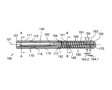
Figures 1-3 show a first guide wire 100 according to
the invention, with Fig. 1 showing a longitudinal
section along a longitudinal center axis 101 of the
first guide wire 100. The guide wire 100 comprises a
two-part hollow shaft 110, wherein a proximal portion
111 of the hollow shaft 110 is made, for example, from
a hollow cylindrical steel tube, while a distal portion
115 is made from a hollow cylindrical polyimide tube
arranged coaxially with respect to the proximal portion
111. A transverse section through the proximal portion
111 of the hollow shaft 110 is shown in Fig. 2. Because
of the choice of material, the elasticity of the distal
portion 115 of the hollow shaft 110 is greater than the
elasticity of the proximal portion 111.
The distal end 112 of the proximal portion 111 tapers
in the distal direction with a constant internal
diameter, whereas the proximal end 116 of the distal
portion 115 widens conically with a constant external
diameter in the proximal direction in a manner
complementary to the distal end 112 of the distal
portion 111. The internal diameters and also the
external diameters of the two portions 111, 115 are
CA 02775946 2012-03-29
- 26 -
substantially the same size, such that a continuous
circular cylindrical lumen 120 with a constant diameter
120.1 is present in the hollow shaft 110.
From the distal end 117 of the distal portion 115, a
coaxially arranged hollow cylindrical wire coil 150
extends in the distal direction away from the hollow
shaft 110. The proximal end 152 of the wire coil 150 is
anchored in the distal end 117 of the distal portion
115 by pressure welding. The wire coil is made, for
example, from a platinum wire with a wire diameter of
ca. 50 m. A transverse section through the wire coil
150 is shown in Fig. 3. A flexibility of the wire coil
150 is greater than the flexibility of the distal
portion 115 of the hollow shaft 110.
A guide-wire tip 170 in the form of an atraumatically
rounded and hemispherical attachment made of plastic is
mounted on the distal end 153 of the wire coil. The
guide-wire tip 170 can be connected to the wire coil
150, for example by pressure welding.
The first and second windings of the wire coil 150, and
the second and third windings thereof, arranged
directly in succession in the proximal direction behind
the guide-wire tip 170 are spaced apart such that, in
the area of the guide-wire tip, a fluid-permeable
through-opening 154 is present in the wire coil 150. A
first spacing 154.1 between the first and second
windings, and a second spacing 154.2 between the second
and third windings, corresponds in each case
approximately to 0.3 times a wire diameter of the wire
coil 150.
The through-opening 154 opens directly into the distal
inner area 151 of the wire coil 150 adjoining the
guide-wire tip 170 in the proximal direction. In other
words, the distal inner area 151 of the wire coil 150
CA 02775946 2012-03-29
- 27 -
thus has an outwardly open through-opening 154 for a
fluid that is to be introduced and/or removed. The
other windings of the wire coil 150 are arranged
bearing directly on one another and form a fluid-tight
and radiopaque portion 155 of the wire coil 150.
An internal diameter 150.1 of the wire coil 150 is
substantially constant along the entire length and
corresponds approximately to an internal diameter of
the hollow shaft 110 or to a diameter of the hollow
cylindrical lumen 120.
In the proximal portion 111 of the hollow shaft 110,
the proximal end 131 of a core wire 130 is also welded
on the boundary surface of the lumen 120 or in the
interior of the hollow shaft 110. The proximal end 131
of the core wire 130 is arranged eccentrically in the
hollow shaft 110. The core wire 130 extends through the
distal portion 115 and the wire coil 130 as far as the
guide-wire tip 170. The distal end 132 of the guide
wire 130 is connected to the guide-wire tip 170, for
example by pressure welding.
The core wire 130 is made, for example, from steel and
has an external diameter decreasing from its proximal
end 131 to its distal end 132, wherein a proximal
external diameter 130.1 at the proximal end 131 of the
core wire 130 is greater than a distal external
diameter 130.2 of the core wire in the area of the wire
coil 150. A flexibility of the guide wire 100 decreases
substantially continuously from the proximal end 131 of
the core wire 130 toward the guide-wire tip 170.
The external diameter 130.1, 130.2 of the core wire 130
is without exception smaller than a diameter 120.1 of
the lumen 120 and smaller than an internal diameter
150.1 of the wire coil 150.
CA 02775946 2012-03-29
- 28 -
In a proximal portion of the wire coil 150, the core
wire 130 is connected to the wire coil 150 via a fluid-
permeable connection 160. The fluid-permeable
connection 160 is, for example, an integrally bonded
connection in the form of a soldered connection. The
fluid-permeable connection 160 is designed
asymmetrically or to one side with respect to the
longitudinal center axis 101 of the guide wire 100,
such that, in the area of the fluid-permeable
connection 160, a channel-like passage 161 alongside
the core wire 130 remains free for the fluid that is to
be delivered and/or withdrawn. The distal inner area
151 of the wire coil 150 thus communicates via the
channel-like passage 161 with a proximal inner area 156
of the wire coil 150. In the transverse section, the
fluid-permeable connection covers about 40% of the
cross-sectional span of the inner area of the wire coil
150. The internal diameter 150.1 of the wire coil 150,
in the area of the fluid-permeable connection 160, is
ca. 3.5 times greater than the proximal external
diameter 130.1 of the core wire 130 in this area.
Thus, the lumen 120 of the first guide wire 100
communicates with the distal inner area 151 of the wire
coil 150 via the channel-like passage 161 formed
alongside the core wire 130, wherein the distal inner
area 151 in turn has a through-opening 154 toward the
outside for delivering and/or withdrawing a fluid.
Fig. 4 shows a second guide wire 200 according to the
invention in a longitudinal section along its
longitudinal center axis 201, while Fig. 5 shows a
transverse section in the area of the fluid-permeable
connection 260 of the second guide wire.
The second guide wire 200 likewise has a hollow shaft
210 with a lumen 220, wherein the hollow shaft 210 and
the lumen 220 of the second guide wire 200 are
CA 02775946 2012-03-29
- 29 -
substantially identical to the hollow shaft 100 and the
lumen 120 of the first guide wire 100. Likewise, the
second guide wire 200 has a wire coil 250 secured on
the hollow shaft 210, with a guide-wire tip 270 and a
core wire 230. The wire coil 250, the guide-wire tip
270 and the core wire 230 are also substantially
identical to the corresponding parts of the first guide
wire 100. Moreover, said parts of the second guide wire
200 are arranged in the same way and secured to one
another in the same way as the corresponding parts of
the first guide wire 100. Accordingly, the wire coil
250 of the second guide wire 200 also has a through-
opening 254 arranged directly behind the guide-wire tip
270 for a fluid that is to be delivered and/or
withdrawn.
In contrast to the first guide wire 100, however, the
second guide wire 200 has a fluid-permeable connection
260 designed as an integrally bonded connection with a
tube 261 embedded therein and extending parallel to the
core wire as a channel-like passage for the fluid that
is to be delivered and/or withdrawn. The tube 261 is,
for example, embedded all the way round in an
integrally bonded manner in a solder composition and
connected to the wire coil 250.
Thus, the lumen 220 of the second guide wire 200
communicates with the distal inner area 251 of the wire
coil 250 via the tube 161, which serves as channel-like
passage and is arranged alongside the core wire 230,
wherein the distal inner area 251 once again has the
through-opening 254 for delivering and/or withdrawing a
fluid.
Fig. 6 shows a third guide wire 300 according to the
invention in a longitudinal section along its
longitudinal center axis 301.
CA 02775946 2012-03-29
- 30 -
The third guide wire 200 likewise has a hollow shaft
310 with a lumen 320, wherein the hollow shaft 310 and
the lumen 320 of the third guide wire 300 are
substantially identical to the hollow shaft 100 and the
lumen 120 of the first guide wire 100. Likewise, the
third guide wire 300 has a wire coil 350 secured on the
hollow shaft 310, with a guide-wire tip 370 and a core
wire 330. The wire coil 350 is likewise made, for
example, from a platinum wire with a diameter of ca. 50
m.
In contrast to the first guide wire 100, however, the
wire coil 350 has several through-openings 354a, 354b,
354c, 354d spaced apart from one another. The first and
second windings of the wire coil 350 lying directly
behind the guide-wire tip 370 in the proximal direction
are spaced apart from one another such that, in the
area of the guide-wire tip 370, a first fluid-permeable
and radiolucent through-opening 354a is present in the
wire coil 150.
In the proximal direction, a first fluid-tight and
radiopaque portion 355a of the wire coil 350 adjoins
the first fluid-permeable through-opening 354a. The
first fluid-tight portion 355a is formed, for example,
by four windings of the wire coil 350 bearing directly
on one another.
In the proximal direction, the first fluid-tight
portion 355a is followed by a second fluid-permeable
and radiolucent through-opening 354b, which is formed
by two spaced-apart windings of the wire coil 350. It
is followed in the proximal direction by a second
fluid-tight and radiopaque portion 355b of the wire
coil 350. Like the first fluid-tight area 355a, the
second fluid-tight area 355b is also formed, for
example, by four windings of the wire coil 350 bearing
directly on one another.
CA 02775946 2012-03-29
- 31 -
In the proximal direction, the second fluid-tight
portion 355b is followed by a third fluid-permeable and
radiolucent through-opening 354c, which is again formed
by two spaced-apart windings of the wire coil 350. The
third through-opening is followed in the proximal
direction by a third fluid-tight and radiopaque portion
355c, which is likewise formed by four windings of the
wire coil 350 bearing directly on one another.
In the proximal direction, the third fluid-tight
portion 355c is followed directly by a fourth fluid-
permeable and radiolucent through-opening 354d formed
by two spaced-apart windings of the wire coil 350.
The fourth fluid-permeable through-opening 354d is
adjoined in the proximal direction by a fourth fluid-
tight and radiopaque portion 355d of the wire coil 350
formed by four windings of the wire coil bearing
directly on one another.
The last wire windings of the wire coil 350 in the
proximal direction, which form the proximal end 352 of
the wire coil, are welded in the distal end 317 of the
hollow shaft 310.
Thus, along the entire length of the wire coil 350,
several fluid-permeable and radiolucent through-
openings 354a, 354b, 354c, 354d are spaced regularly
apart from one another and a separated by several
fluid-tight and radiopaque portions 355a, 355b, 355c,
355d. The spaced-apart through-openings 354a, 354b,
354c, 354d each have, for example, a width which,
measured in a direction parallel to the longitudinal
center axis 301, is ca. 0.5 times the wire diameter of
the wire coil 350.
CA 02775946 2012-03-29
- 32 -
In the area of the fourth fluid-tight portion 355d, the
core wire 370 protruding from the hollow shaft 310 and
extending through the wire coil 350 as far as the
guide-wire tip is connected to the wire coil 350 via a
fluid-permeable connection 360. The fluid-permeable
connection 360 has substantially the same design as the
fluid-permeable connection 160 of the first guide wire
100 and is present, for example, as an integrally
bonded connection in the form of a soldered connection.
The fluid-permeable connection 360 is accordingly
designed asymmetrically or to one side with respect to
the longitudinal center axis 301 of the third guide
wire 300, such that, in the area of the fluid-permeable
connection 360, a channel-like passage 261 alongside
the core wire 130 remains free for the fluid that is to
be delivered and/or withdrawn. In the transverse
section, the fluid-permeable connection covers about
40% of the cross-sectional span of the inner area of
the wire coil 350. The internal diameter of the wire
coil 350, in the area of the fluid-permeable connection
360, is ca. 3.5 times greater than the external
diameter of the core wire 330 in this area.
Thus, the lumen 320 of the third guide wire 300
communicates with the distal inner area 351 of the wire
coil 350 via the channel-like passage 361 formed
alongside the core wire 330, wherein the distal inner
area 351 again has the four through-openings 354a,
354b, 354c, 354d for delivering and/or withdrawing a
fluid.
Figures 7 and 8 show a fourth guide wire 400 according
to the invention in a longitudinal section along the
longitudinal axis 401 and in a transverse section. The
hollow shaft 410, the wire coil 450, the guide-wire tip
370 and the core wire 430 of the fourth guide wire 400
are substantially identical to the corresponding parts
of the first guide wire 100. Accordingly, the wire coil
CA 02775946 2012-03-29
- 33 -
450 has a fluid-permeable through-opening 454 which is
arranged directly behind the guide-wire tip 370 in the
proximal direction and which is formed by three spaced-
apart windings of the wire coil and communicates with
the distal inner area 451 of the wire coil. The
through-opening 454 of the fourth wire coil 450
corresponds substantially to the through-opening 151 of
the first guide wire 100.
In contrast to the first guide wire 100, however, the
fourth guide wire 400 additionally has a tubular stub
480 in the form of a hollow cylindrical tube which,
coaxially with respect to the longitudinal center axis
401 of the fourth guide wire 400, protrudes from the
hollow shaft 410 into the inner area of the wire coil
450. A proximal end 481 of the tubular stub 480 is
anchored in a distal end 417 of the hollow shaft 410,
e.g. by adhesive bonding and/or welding. The external
diameter of the tubular stub 480 corresponds
substantially to the internal diameter of the hollow
shaft 410 and to the internal diameter of the wire coil
450.
A proximal portion of the tubular stub 480 is
connected, for example by an adhesive connection, to
the proximal portion of the wire coil 450.
A distal end of the tubular stub 480 is arranged in the
distal direction directly in front of the through-
opening 454, such that the through-opening 454 is not
covered by the tubular stub 480 and thus remains free.
The core wire 430 of the fourth guide wire 400 extends
through the tubular stub 480, wherein an internal
diameter of the tubular stub 480 is without exception
smaller than an external diameter of the core wire 430
in this area. Thus, a channel-like passage 461, through
which a fluid to be delivered and/or withdrawn can
CA 02775946 2012-03-29
- 34 -
pass, remains free in the tubular stub 480 alongside
the core wire 430.
Thus, by way of the channel-like passage 461 present in
the tubular stub 480, the lumen 420 of the fourth guide
wire 400 communicates with the distal inner area 451 of
the wire coil 450, which again has a fluid-permeable
through-opening 454 for delivering and/or withdrawing a
fluid.
Fig. 9 shows the first guide wire 100 from Figures 1-3
after it has been pushed into a blood vessel 500. The
guide-wire tip 170 lies directly in front of a narrowed
location 501 in the blood vessel 500, which is to be
treated, for example, by drugs. In the area of the
proximal end of the guide wire 100 lying outside the
body (and not shown in Fig. 9), the drug 502 to be
administered can be introduced into the lumen 120 and
can be fed into the vessel 500 via the through-opening
154 lying directly behind the guide-wire tip 170. Since
the through-opening 154 lies directly in the area of
the guide-wire tip 170, the drug to be administered
passes relatively precisely into the area of the
constriction 501 that is to be treated.
The embodiments described above are to be understood
merely as illustrative examples, which can be modified
in any desired way within the context of the invention.
Thus, in all of the guide wires 100, 200, 300, 400, it
is possible, for example, to replace the two-part
hollow shafts 110, 210, 310, 410 with one-part hollow
shafts. These can be present, for example, in the form
of a steel tube. In this case, the wire coil can be
welded onto the front face of the hollow shaft, for
example. It is also possible, of course, to use multi-
part hollow shafts with three, four or more separate
subsidiary portions. Regardless of whether they are in
CA 02775946 2012-03-29
- 35 -
one, two or more parts, the hollow shafts 110, 210,
310, 410 can also be designed tapering in the distal
direction for example, in order in particular to
improve the insertability.
The distal end area 112 of the proximal portion 111
and/or the proximal end area 116 of the distal portion
115 of the hollow shaft 100 can also be differently
designed and/or connected. For example, the two
portions 111, 115 can be joined together in abutment,
via in each case an annular front face lying
perpendicularly with respect to the longitudinal center
axis 101, and adhesively bonded and/or welded.
Likewise, the guide-wire tips 170, 270, 370, 470 can
also be differently designed and, for example, adapted
to a specific purpose.
In addition to the fluid-permeable connections 160,
260, 360, further connections can also be formed
between core wire 130, 230, 330 and wire coil 150, 250,
350. However, it is also possible in principle to do
completely without the fluid-permeable connections 160,
260, 360. Likewise, in the fourth guide wire 400, an
additional fluid-permeable connection can be formed
between core wire and tubular stub 480, for example in
order to additionally increase the stability of the
wire coil.
In the fluid-permeable connection 260 of the second
guide wire 200, further tubes can also be present in
addition to the tube 261, for example in order to
increase the fluid-permeable cross-sectional surface
area.
It is also possible in principle for the wire coils
150, 250, 350, 450 to be designed tapering in the
distal direction toward the guide-wire tips if this
CA 02775946 2012-03-29
- 36 -
appears appropriate. In some circumstances, this can
improve the insertability of the guide wires.
In the third guide wire 300, it is also possible to
provide more or fewer through-openings than the four
through-openings 354a, 354b, 354c, 354d of the wire
coil 450. It is thus conceivable, for example, for all
of the windings of the wire coil 450 to be spaced
apart, such that a fluid can be delivered and/or
withdrawn along the entire length of the wire coil. A
corresponding design is also possible in the wire coils
150, 250 of the first two guide wires 100, 200.
In the first guide wire 100, the proximal end 131 of
the core wire 130 can in principle also be mounted in
the distal portion 115 of the hollow shaft 110. The
core wire 130 can also have areas with external
diameters decreasing and/or increasing in stages, for
example in order to compensate for abrupt changes in
elasticity. In principle, however, the core wire can
also have an external diameter that is constant along
the entire length.
All of the guide wires 100, 200, 300, 400 can also be
designed, for example, with an oval cross section, if
this is advantageous for certain uses.
It is also possible to provide additional through-
openings on the hollow shafts 110, 210, 310, 410
themselves, if this appears appropriate.
It can be stated in conclusion that novel guide wires
have been created that can be inserted easily into
human and/or animal hollow organs and that also permit
highly precise and targeted introduction and/or removal
of fluids at defined locations in human and/or animal
hollow organs.