Note: Descriptions are shown in the official language in which they were submitted.
CA 02775948 2016-03-07
ROTARY SURFACE CLEANING TOOL
FIELD OF THE INVENTION
The present invention relates generally to a rotary tool for cleaning
surfaces,
including rugs and carpets, and in particular to such apparatus and methods
with brushes for
coaction with cleaning liquid delivering means and suction extraction means.
BACKGROUND OF THE INVENTION
Many apparatuses and methods are known for cleaning carpeting and other
flooring,
wall and upholstery surfaces. The cleaning apparatuses and methods most
commonly used
today apply cleaning fluid as a spray under pressure to the surface whereupon
the cleaning
fluid dissolves the dirt and stains and the apparatus scrubs the fibers while
simultaneously
applying suction to extract the cleaning fluid and the dissolved soil. Many
different
apparatuses and methods for spraying cleaning fluid under pressure and then
removing it
with suction are illustrated in the prior art. Some of these cleaning
apparatuses and methods
use a rotating device wherein the entire machine is transported over the
carpeting while a
cleaning head is rotated about a vertical axis.
Another category of carpeting and upholstery cleaning apparatuses and methods
using
the rotating device wherein the entire machine is transported over the
carpeting while a
cleaning head is rotated about a vertical axis includes machines having a
plurality of arms,
each of having one or more spray nozzles or a suction means coupled to a
vacuum source.
These rotary cleaning tools providing a more intense scrubbing action since,
in general, more
scrubbing surfaces contact the carpet. These apparatuses and methods are
primarily
illustrated in U.S. Pat. No. 4,441,229 granted to Monson on April 10, 1984,
and are listed in
the prior art known to the inventor but not discussed in detail herein.
A third category of carpeting and upholstery cleaning apparatuses and methods
that
attempt to deflect or otherwise control the cleaning fluid are illustrated by
U.S. Pat. No.
6,243,914, which was granted to the inventor of the present patent application
June 12, 2001,
. U.S. Pat. No. 6,243,914 discloses a cleaning
head for carpets, walls or upholstery, having a rigid open-bottomed main body
that defines a
surface subjected to the cleaning process. Mounted within or adjacent to the
main body and
1
CA 02775948 2012-05-03
coplanar with the bottom thereof is a fluid-applying device which includes a
slot at an acute
angle to the plane of the bottom of the body located adjacent the plane of the
bottom of the
body, the slot configured such that the fluid is applied in a thin sheet that
flows out of the slot
and into the upper portion of the surface to be cleaned and is subsequently
extracted by
suction into the vacuum source for recovery. The cleaning head is
alternatively multiply
embodied in a plurality of arms which are rotated about a hub.
FIG. 1 illustrates a typical prior art professional fluid cleaning system as
illustrated in
U.S. Pat. 6,243,914. It is to be understood that this cleaning system is
typically mounted in a
van or truck for mobile servicing of carpets and flooring in homes and
businesses. The
typical truck-mounted fluid cleaning system 1 includes a main liquid waste
receptacle 3 into
which soiled cleaning fluid is routed. A cleaning head or nozzle 5 is mounted
on a rigid
vacuum wand 7 which includes a handle 8 for controlling cleaning head 5. A
supply of
pressurized hot liquid solution of cleaning fluid is supplied to cleaning head
5 via a cleaning
solution delivery tube 9 arranged in fluid communication with a cleaning
solution inlet
orifice 11 of cleaning head 5 for delivering there through a flow of
pressurized liquid
cleaning solution to fluid cleaning solution spray jets 13 of cleaning head 5.
Carpet cleaning
head 5 typically includes a rectangular, downwardly open truncated pyramidal
envelope 15
which contains the cleaning fluid spray that is applied to the carpet or other
flooring, as well
as forming a vacuum plenum for the vacuum retrieving the soiled liquid for
transport to
waste receptacle 3. An intake port 16 of the vacuum wand 7 is coupled in fluid
communication with the vacuum plenum of cleaning head 5.
Mounted above the main waste receptacle 3 is a cabinet 17 housing a vacuum
source
and supply of pressurized hot liquid cleaning fluid. Soiled cleaning fluid is
routed from
cleaning head 5 into waste receptacle 3 via rigid vacuum wand 7 and a flexible
vacuum
return hose 19 coupled in fluid communication with an exhaust port 20 thereof,
whereby
spent cleaning solution and dissolved soil are withdrawn under a vacuum force
supplied by
the fluid cleaning system, as is well known in the art. A vacuum control valve
or switch 21 is
provided for controlling the vacuum source.
FIG. 2 illustrates details of operation of the typical truck-mounted fluid
cleaning
system 1 illustrated in FIG. 1. Here, the main waste receptacle 3, as well as
the vacuum
source and cleaning fluid supply cabinet 17, are shown in partial cut-away
views for
V84873CANAN_LAW\ 975492\1 2
CA 02775948 2016-03-07
exposing details thereof The cleaning fluid is drawn through cleaning solution
delivery tube
9 from a supply 23 of liquid cleaning solution in the cabinet 17. The vacuum
for vacuum
return hose 19 is provided by a vacuum suction source 25, such as a high
pressure blower,
driven by a power supply 27. The blower vacuum source 25 communicates with the
main
waste receptacle 3 through an air intake 29 coupled into an upper portion 31
thereof and,
when operating, develops a powerful vacuum in an air chamber 33 enclosed in
the receptacle
3.
Vacuum return hose 19 is coupled in communication with waste receptacle 3
through
a drain 35, for example, at upper portion 31, remote from intake 29. Vacuum
return hose 19
feeds soiled cleaning fluid into waste receptacle 3 as a flow 37 of liquid
soiled with dissolved
dust, dirt and stains, as well as undissolved particulate material picked up
by the vacuum
return but of a size or nature as to be undissolvable in the liquid cleaning
fluid. The flow 37
of soiled cleaning fluid enters into waste receptacle 3 through drain 35 and
forms a pool 39
of soiled liquid filled with dissolved and undissolved debris. A float switch
41 or other means
avoids overfilling the waste receptacle 3 and inundating the blower 25 through
its air intake
29. A screen or simple filter may be applied to remove gross contaminates from
the soiled
liquid flow 37 before it reaches the pool 39, but this is a matter of operator
choice since any
impediment to the flow 37 reduces crucial vacuum pressure at the cleaning head
5 for
retrieving the soiled liquid from the cleaned carpet or other 'surface.
Soiled liquid cleaning fluid effectively filters air drawn into the waste
receptacle 3 by
dissolving the majority of dust, dirt and stains, and drowning and sinking any
undissolved
debris whereby it is sunk into the pool 39 of soiled liquid and captured
therein. Thus, the
soiled liquid in the vacuum return hose 19 effectively filters the air before
it is discharged
into the enclosed air chamber 34, and no airborne particles of dust and dirt
are available to
escape into the enclosed air chamber 33 floating above the liquid pool 39.
In a rotary surface cleaning tool, cleaning head 5 utilizes cleaning liquid
delivering
means and suction extraction means in combination with a rotary cleaning plate
that is
coupled for high speed rotary motion.
One example of a rotary surface cleaning tool is illustrated by U.S. Pat. No.
4,182,001, SURFACE CLEANING AND RINSING DEVICE, issued to Helmuth W. Krause
on January 8, 1980.
3
CA 02775948 2012-05-03
FIG. 3 illustrates the rotary surface cleaning and rinsing machine of Krause,
indicated
generally at 50, which includes a substantially circular housing 51 and frame
53 with its
lower axial face open at 55, with this face 55 being disposed substantially
parallel to the
surface which is to be cleaned, such as a rug 57. Mounted on top of the
housing 51 and frame
53 is an enclosure 59 from which extends a handle assembly 61. Handle assembly
61 is held
by the operator during the manipulation of machine 50. Handle assembly 61 has
operating
levers 63 and 65. Control handle 65 regulates flow of cleaning or rinsing
fluid to rotary
surface cleaning tool 51 through feed line 67. For example, feed line 67 is
coupled to
cleaning solution delivery tube 9 from supply 23 of liquid cleaning solution
in cabinet 17 in a
truck-mounted unit, or another supply of liquid cleaning solution. Control
handle 63 can be
used to regulate the starting and stopping of drive motors.
An exhaust pipe or tube 69 is mounted on handle assembly 61 and is connected
to the
top of rotary surface cleaning tool 51 at a connection 71. Suction is created
by the motor and
fan assembly 73. Else, exhaust pipe or tube 69 is coupled for suction
extraction to vacuum
return hose 19 and vacuum source 25 in a truck-mounted unit. Soiled cleaning
fluid extracted
by suction extraction from carpet or rug 57 is drawn off through outlet
connection 71 and
through discharge hose 69. Frame 53 may also be supported by a swivel wheel
75. A large
rotor 77 is rotationally mounted within housing 51 and rotationally coupled
within enclosure
59. Rotor 77 is drivingly connected by a drive belt or chain 79 to an output
shaft 81 of an
electric motor 83 mounted on the frame 53. Motor 83 serves to turn large rotor
77. A
plurality of circular brushes 85 are located on rotor 77.
FIG. 4 illustrates brushes 85 are rotated as shown by arrows 87 in the
opposite
direction from the turning motion 89 of the rotor 77 by a rotating drive means
for
contrarotating brushes 85 with respect to rotor 77. Moreover, brushes 85 are
rotated at
significantly higher revolutions per minute (RPM) than rotor 77 for producing
a very
vigorous brush scrubbing action. For example, brushes 85 rotate more than
seven times with
respect to rug 57 for each full rotation of rotor 77. As a result, the brush
elements or bristles
in the peripheral region traveling very rapidly in a backward direction 87
relative to rotor 77
tend to lift up and to flip over the matted pile of rug 57 thereby exposing
and scrubbing its
underside. Then, in interior regions 91 where brush elements or bristles are
traveling in the
same direction as rotor 77, they flip the pile back into its original position
for scrubbing it on
V84873CAWAN_LAW\ 975492\1 4
CA 02775948 2012-05-03
the other side. Thus, the pile of rug 57 becomes thoroughly scrubbed on its
underside as well
as on its upper side. A cyclic scrubbing action is produced flipping the
matted pile back and
forth many times during one pass of machine 50.
Also positioned on rotor 77 are suction extraction nozzles 93 spaced between
brushes
85 and communicating with discharge hose 69. Suction extraction nozzles 93 are
fixed to
rotor 77 and each is provided with a relatively narrow vacuum extraction slot
95. Each
vacuum extraction slot 95 is positioned coplanar with the ends of the brush
elements or
bristles of brushes 85 distal from rotor 77.
Also mounted on rotor 77 is a plurality of spray nozzle means 97 for
dispensing
cleaning or rinsing liquid. Each of spray nozzle means 97 can be mounted for
angular
adjustment so as to direct sprays of cleaning or rinsing liquid through
individual nozzles 99
onto rug 57 at different angles. The cleaning or rinsing fluid is conveyed to
nozzle means 97
through line 67 which leads to a supply of cleaning or rinsing fluid, such as
either feed line
67 or solution delivery tube 9.
During operation of the cleaning device, rotor 77 rotates in the direction
indicated by
arrow 89. As the cleaning liquid is sprayed onto rug 57 through nozzles 99,
rotating brushes
85 agitate the pile of rug 57 in conjunction with the cleaning liquid to
loosen dirt in or on the
surface. The spent cleaning liquid and loosened dirt are extracted up by the
next succeeding
suction extraction nozzle 93. Accordingly, the liquid-dwell-time is solely
controlled by
machine 50, and not by the rate at which the operator advances machine 50 over
the floor.
However, known rotary surface cleaning tool are limited in their ability to
effectively
provide the desired cleaning of target floor surfaces and extraction of soiled
cleaning liquid.
SUMMARY OF THE INVENTION
The present invention is a rotary surface cleaning machine for cleaning
floors,
including both carpeted floors and uncarpeted hard floor surfaces including
but not limited to
wood, tile, linoleum and natural stone flooring. The rotary surface cleaning
machine has a
rotary surface cleaning tool mounted on a frame and coupled for high speed
rotary motion
relative to the frame. The rotary surface cleaning tool has a substantially
circular operational
surface that performs the cleaning operation. The rotary surface cleaning tool
is driven by an
on-board power plant to rotate at a high rate. The rotary surface cleaning
tool is coupled to a
V84873CA\VAN_LAW\ 975492\1 5
CA 02775948 2012-05-03
supply of pressurized hot liquid solution of cleaning fluid and a powerful
vacuum suction
source.
According to one aspect of the invention a plurality of individual arrays of
cleaning
solution delivery spray nozzles are substantially uniformly angularly
distributed across the
operational surface of the rotary surface cleaning tool, the arrays of spray
nozzles being
coupled in fluid communication with a pressurized flow of cleaning fluid
through a plurality
of individual liquid cleaning fluid distribution channels of a cleaning fluid
distribution
manifold portion of the rotary surface cleaning tool. Each of the plurality of
individual arrays
of cleaning solution delivery spray nozzles includes a plurality of individual
delivery spray
nozzles that are radially oriented across the substantially circular
operational surface of the
rotary surface cleaning tool, and each individual array of the spray nozzles
extends across a
portion of the operational surface that is substantially less than an annular
portion thereof
extended between an inner radial limit and an outer radial limit. Individual
ones of the arrays
of spray nozzles are positioned in a substantially spiral pattern across the
annular portion of
the operational surface of the rotary surface cleaning tool between the inner
radial limit of the
annular portion and receding therefrom over the annular portion toward the
outer radial limit
thereof.
This spiral pattern of individual array of spray nozzles greatly reduces the
number of
individual delivery spray nozzles that must be supplied on the operational
surface of the
rotary surface cleaning tool. However, the high speed of rotation ensures that
sufficient
quantities of cleaning solution is delivered since each individual array of
spray nozzles is
presented to the target floor area at least one, two or several times each
second. The spray
nozzles are very expensive to drill or otherwise form because they are only
about 0.03 inch in
diameter. Therefore, a large cost savings is gained, while the delivery of
cleaning solution
does not suffer. Forming the array of spray nozzles in the spiral pattern so
that the individual
array of spray nozzles to cover only a fractional portion of the operational
surface of the
rotary surface cleaning tool also ensures that the cleaning solution is
delivered with
substantially uniform pressure across the entire radius of the rotary surface
cleaning tool,
without resorting to special design features normally required in the prior
art to provide
uniform pressure across each spray nozzle array that extends across at least a
large portion of
radius of the rotary surface cleaning tool, or else the entire radius.
V84873CA\VAN_LAW\ 975492\1 6
CA 02775948 2012-05-03
According to another aspect of the invention a plurality of suction extraction
shoes
are also substantially uniformly angularly distributed across the operational
surface of the
rotary surface cleaning tool alternately between the arrays of cleaning
solution delivery spray
nozzles and are projected from the operational surface of the rotary surface
cleaning tool by a
biasing means that is structured for individually biasing each suction
extraction shoe
outwardly relative to bottom operational surface of the rotary surface
cleaning tool. For
example, a resilient cushion, such as a closed-cell foam rubber cushion of
about one-quarter
inch thickness or thereabout, is positioned between a flange portion of each
shoe and the
rotary surface cleaning tool.
Each of the suction extraction shoes is further formed with a fluid extraction
passage
presented in a position adjacent to the operational surface of the rotary
surface cleaning tool.
The fluid extraction passage of each suction extraction shoe communicates
through one of a
plurality of manifold branch passages within the rotary surface cleaning tool
with a vacuum
plenum that is in fluid communication with the vacuum suction source.
According to another aspect of the invention the rotary surface cleaning tool
has a
target surface scrubbing means for causing a washboard-type scrubbing effect
of a moveable
target surface to be cleaned, i.e., a carpet. The target surface scrubbing
means causes
oscillations of the moveable target surface alternately toward and away from
the operational
surface of the rotary surface cleaning tool by alternate application of vacuum
suction pulling
the carpet toward the operational surface of the rotary surface cleaning tool
and application
of compression by the next consecutive shoe pushing the carpet away from the
operational
surface of the rotary surface cleaning tool.
According to another aspect of the invention the target surface scrubbing
means for
causing a washboard-type scrubbing effect is one or both of (a) a relatively
raised surface
portion of each suction extraction shoe that projects further from the
operational surface of
the rotary surface cleaning tool than a relatively lower surface portion
thereof, and (b) one or
more rows of bristle brushes arranged along a surface portion of each suction
extraction shoe
and projected further from the operational surface of the rotary surface
cleaning tool than a
surface of the corresponding suction extraction shoe. The relatively raised
surface portion of
each suction extraction shoe, or the one or more rows of bristle brushes,
whichever is present,
the leading surface portion of the suction extraction shoe as a function of a
direction of the
V84873CA\VAN_LAW\ 975492\1 7
CA 02775948 2012-05-03
rotary motion of the operational surface of the rotary surface cleaning tool,
while the
relatively lower surface or brushless portion forms the trailing surface
portion of the suction
extraction shoe.
When present, the rows of bristle brushes provide a more aggressive cleaning
action
in cleaning when provided in combination with fluid cleaning of carpet or
other target
flooring surface. Furthermore, when present the optional raised bristle
brushes effectively
raise bottom operational surface of the rotary surface cleaning tool slightly
away from target
floor surface so that the rotary surface cleaning machine can be alternated
between carpeting
and hard floor surfaces such as wood, tile, linoleum and natural stone
flooring, without
possibility of scarring or other damage to either the operational surface of
the rotary surface
cleaning tool or the hard floor surfaces.
Other aspects of the invention are detailed herein.
BRIEF DESCRIPTION OF THE DRAWINGS
The foregoing aspects and many of the attendant advantages of this invention
will
become more readily appreciated as the same becomes better understood by
reference to the
following detailed description, when taken in conjunction with the
accompanying drawings,
wherein:
FIG. 1 illustrates a typical prior art professional fluid cleaning system of a
type that is
typically mounted in a van or truck for mobile servicing of carpets and
flooring in homes and
businesses;
FIG. 2 illustrates details of operation of the typical truck-mounted fluid
cleaning
system illustrated in FIG. 1;
FIG. 3 illustrates one rotary surface cleaning and rinsing machine of the
prior art;
FIG. 4 is another view of the rotary surface cleaning and rinsing machine of
the prior
art as illustrated in FIG. 3;
FIG. 5 illustrates the rotary surface cleaning machine of the invention for
delivery of
liquid cleaning fluid to a target surface to be cleaned, such as either
carpeting or hard floor
surfaces including but not limited to wood, tile, linoleum and natural stone
flooring;
V84873CAWAN_LAW\ 97549211 8
CA 02775948 2012-05-03
FIG. 6 is a side view of the rotary surface cleaning machine illustrated in
FIG. 5,
wherein a plurality of suction extraction shoes are more clearly illustrated
as being located on
a rotary surface cleaning tool and projected from an open lower axial face of
a housing dome;
FIG. 7 is a bottom view of the rotary surface cleaning machine illustrated in
FIG. 5
and FIG. 6, wherein the plurality of suction extraction shoes are more clearly
illustrated as
being located on the rotary surface cleaning tool in the open lower axial face
of the housing
dome;
FIG. 7A is another bottom view of the rotary surface cleaning machine
illustrated in
FIG. 5 and FIG. 6, wherein a relatively narrow annular suction or vacuum
extraction passage
is formed as a substantially continuous annular slot between the bottom
cleaning surface of
the rotary surface cleaning tool and the housing dome at its lower axial face
for closer
approach to walls and other surfaces projected from the floor;
FIG. 8 illustrates the rotary surface cleaning tool of the rotary surface
cleaning
machine illustrated in FIGS. 5 through FIG. 7, wherein the rotary surface
cleaning tool is
mounted on the support frame with an on-board power plant;
FIG. 9 is a partial cross-section view of the rotary surface cleaning machine
illustrated in FIG. 5 through FIG. 8, wherein the rotary surface cleaning tool
is mounted on
the support frame through a rotary coupling;
FIG. 9A illustrates a relatively narrow annular suction or vacuum extraction
passage
formed as a substantially continuous annular slot between the bottom cleaning
surface of the
rotary surface cleaning tool and the housing dome, and further illustrates an
alternative
vacuum plenum that is useful for cleaning trapped debris from the vacuum
passage;
FIG. 9B is an exploded view showing operation of the alternative vacuum plenum
of
FIG. 9A;
FIG. 9C is another exploded view showing operation of the alternative vacuum
plenum of FIG. 9A and FIG. 9B;
FIG. 10 illustrates the rotary surface cleaning tool of the rotary surface
cleaning
machine illustrated in FIG. 5 through FIG. 9, wherein the rotary surface
cleaning tool is
drivingly connected, for example but without limitation, by a drive gear to
the rotary drive
output of the on-board power plant;
V84873CA\VAN_LAW\ 975492\1 9
CA 02775948 2012-05-03
FIG. 11A illustrates an upper coupling surface of the rotary surface cleaning
tool of
the rotary surface cleaning machine of the prior art;
FIG. 11B illustrates an upper coupling surface of the rotary surface cleaning
tool of
the rotary surface cleaning machine illustrated in FIG. 5 through FIG. 9, as
further illustrated
in FIG. 10, and further illustrates the vacuum manifold having an optional
curved portion that
actually generates a pumping action of the suction pressure;
FIG. 12 illustrates a bottom operational surface of the rotary surface
cleaning tool of
the rotary surface cleaning machine illustrated in FIG. 5 through FIG. 9, as
further illustrated
in FIG. 10 and FIG. 11;
FIG. 13 is a detail view of one embodiment of the suction extraction shoe of
the
rotary surface cleaning machine illustrated in FIG. 5 through FIG. 9;
FIG. 14 is a detailed cross-section view of one embodiment of the suction
extraction
shoe illustrated in FIG. 13, wherein the suction extraction shoe is shown as
having a leading
surface and a trailing surface as a function of the rotational direction of
the rotary surface
cleaning tool;
FIG. 15 illustrates the bottom operational surface of the rotary surface
cleaning tool
of the rotary surface cleaning machine illustrated in FIG. 5 through FIG. 9,
having the
suction extraction shoe with an optional raised leading surface portion and a
relatively lower
trailing surface portion as illustrated in FIG. 13 and FIG. 14;
FIG. 16 illustrates bottom the operational surface of the rotary surface
cleaning tool
of the rotary surface cleaning machine illustrated in FIG. 5 through FIG. 9,
having a spiral
pattern of cleaning solution delivery spray nozzle arrays of individual
delivery holes, wherein
each spray nozzle array consists of one to about four individual delivery
holes, and wherein
the individual spray nozzle arrays are positioned in a spiral pattern across
the bottom
operational surface of the rotary surface cleaning tool;
FIG. 16A illustrates an alternative configuration of the spiral pattern of
cleaning
solution delivery spray nozzle arrays illustrated in FIG. 16;
FIG. 17 is a detail view of another embodiment of the suction extraction shoe
of the
rotary surface cleaning machine illustrated in FIG. 5 through FIG. 9, wherein
the leading
surface does not include the optional raised portion but is rather
substantially coplanar with
V84873CAWAN_LAW\ 975492\1 10
CA 02775948 2012-05-03
the trailing surface, but the leading surface rather includes one or more
bristle brushes in one
or more rows arranged along an outermost portion thereof;
FIG. 18 is a detailed cross-section view of the embodiment of the suction
extraction
shoe illustrated in FIG. 17;
FIG. 19 illustrates the operational surface of the rotary surface cleaning
tool of the
rotary surface cleaning machine illustrated in FIG. 5 through FIG. 9, wherein
the suction
extraction shoes are configured with substantially coplanar leading and
trailing surfaces, and
the shoe leading surfaces have one or more of the bristle brushes in one or
more rows
arranged along the outermost portions thereof;
FIG. 20 illustrates rotary surface cleaning tool of the rotary surface
cleaning machine
illustrated in FIG. 5 through FIG. 9, wherein each suction extraction shoe is
supported in the
bottom operational surface by a biasing means structured for individually
biasing or
"floating" each suction extraction shoe outwardly relative to the bottom
operational surface
of the rotary surface cleaning tool;
FIG. 21 is a cross-section view of the rotary surface cleaning tool of the
rotary surface
cleaning machine illustrated in FIG. 5 through FIG. 9, wherein the biasing
means for
individually biasing or "floating" each suction extraction shoe outwardly
relative to the
bottom operational surface of the rotary surface cleaning tool is structured,
by example and
without limitation, as a resilient cushion, such as a closed-cell foam rubber
cushion of about
one-quarter inch thickness or thereabout, that is positioned between a flange
portion of each
shoe and the rotary surface cleaning tool;
FIG. 22 is a detail view of another embodiment of the suction extraction shoe
of the
rotary surface cleaning machine illustrated in FIG. 5 through FIG. 9, wherein
each suction
extraction shoe is structured for accomplishing the "washboard" scrubbing
effect of the
moveable target surface, i.e. carpet surface, independently of the next
consecutive suction
extraction shoe;
FIG. 23 is a detailed cross-section view of the embodiment of the suction
extraction
shoe illustrated in FIG. 22, wherein the suction extraction shoe is shown as
having the
optional relatively lower or recessed portion formed on the leading surface
and the relatively
raised portion is formed on the trailing surface as a function of the reversed
clockwise
rotational direction of the rotary surface cleaning tool; and
V84873CA\VAN_LAW\ 975492\1 11
CA 02775948 2016-03-07
FIG. 24 illustrates the bottom operational surface of the rotary surface
cleaning tool
of the rotary surface cleaning machine illustrated in FIG. 5 through FIG. 9,
having the
suction extraction shoe formed with the optional relatively lower or recessed
surface portion
on its leading surface, and the optional relatively raised surface portion
formed on the trailing
surface as illustrated in FIG. 22 and FIG. 23.
DETAILED DESCRIPTION OF PREFERRED EMBODIMENT
In the Figures, like numerals indicate like elements.
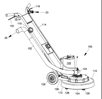
FIG. 5 illustrates a rotary surface cleaning machine 100 of a type for
delivery of
liquid cleaning fluid to a target surface to be cleaned, such as either
carpeting or hard floor
surfaces including but not limited to wood, tile, linoleum and natural stone
flooring. Rotary
surface cleaning machine 100 is coupled to draw liquid cleaning fluid through
cleaning
solution delivery tube 9 from a supply 23 of liquid cleaning solution in the
cabinet 17.
Rotary surface cleaning machine 100 is optionally a stand-alone unit coupled
to a
supply of pressurized hot liquid solution of cleaning fluid and a having an on-
board motor or
other power plant coupled for driving a fan assembly for generating a suction
as, for
example, rotary tool for cleaning surfaces disclosed by U.S. Pat. No.
4,182,00L
Alternatively, rotary surface cleaning machine 100 is part
of a truck-mounted fluid cleaning system such as illustrated in FIG. 1 and
FIG. 2 and
disclosed in U.S. Pat. 6,243,914_ When part of
a
truck-mounted fluid cleaning system, rotary surface cleaning machine 100 is
coupled to
vacuum return hose 19 and truck-mounted vacuum source 25 by means of an
exhaust pipe or
hose 102 coupled to an exhaust port 104. Fluid extraction suction is generated
by the vacuum
force supplied by vacuum source 25. Soiled cleaning fluid extracted from
carpet or rug 57 is
drawn off through exhaust port 104 and carried through flexible vacuum return
hose 19 to
main waste receptacle 3.
As illustrated here by example and without limitation, rotary surface cleaning
machine 100 includes a support frame member 106, which may be supported by a
wheel
assembly 108. Support frame 106 carries a substantially circular housing dome
110 having its
lower axial face open at 112 with this face 112 being disposed substantially
parallel to the
surface which is to be cleaned, such as rug 57. A pivotally mounted handle
assembly 114 is
12
CA 02775948 2012-05-03
used by the operator during operation for manipulating machine 100. Handle
assembly 114
supports one or more operating control mechanisms mounted thereon for the
convenience of
the operator. For example, one flow control mechanism 116 regulates flow of
cleaning fluid
through cleaning solution delivery tube 9. A conventional quick connection can
be used for
supplying the liquid cleaning solution. Another vacuum control mechanism 118
can be used
to regulate the suction extraction of spent cleaning liquid and loosened dirt.
A rotary control
mechanism 120 can be used to regulate the starting and stopping of the rotary
surface
cleaning tool through control of an on-board power plant 122, such as an
electric motor or
other power plant, mounted on support frame 106.
A rotary surface cleaning tool 124 is configured as a large rotor that is
joumaled with
support frame 106 for high speed rotary motion within housing dome 110. On-
board power
plant 122 is coupled for driving the high speed rotary motion of rotary
surface cleaning tool
124.
A plurality of suction extraction shoes 126 are located on rotary surface
cleaning tool
124 and project from open lower axial face 112 of housing dome 110. Each
suction
extraction shoe 126 is coupled in fluid communication with vacuum source 25
through
exhaust port 104 and exhaust pipe or hose 102 for the suction extraction of
spent cleaning
liquid and loosened dirt.
FIG. 6 is a side view of the rotary surface cleaning machine 100 illustrated
in FIG. 5,
wherein the plurality of suction extraction shoes 126 are more clearly
illustrated as being
located on rotary surface cleaning tool 124 and projected from open lower
axial face 112 of
housing dome 110.
FIG. 7 is a bottom view of the rotary surface cleaning machine 100 illustrated
in FIG.
5 and FIG. 6, wherein the plurality of suction extraction shoes 126 are more
clearly
illustrated as being located on rotary surface cleaning tool 124 in open lower
axial face 112
of housing dome 110.
As disclosed herein, a rotary drive output 128 of on-board power plant 122 is
coupled
for driving the high speed rotary motion of rotary surface cleaning tool 124.
For example,
rotary surface cleaning tool 124 is rotationally mounted within housing dome
110 and is
drivingly connected, for example but without limitation by any of: a drive
belt, a drive chain,
or a drive gear, to rotary drive output 128 of on-board power plant 122
mounted on frame
V84873CA\VAN_LAW\ 975492\1 13
CA 02775948 2012-05-03
106. Here, by example and without limitation, rotary drive output 128 of on-
board power
plant 122 is a drive gear coupled to drive a circumferential tooth gear 130
disposed about the
circumference of rotary surface cleaning tool 124. Accordingly, drive means
alternative to
the rotary gear drive disclosed herein by example and without limitation are
also
contemplated and may be substituted without deviating from the scope and
intent of the
present invention. Power plant 122 thus serves to turn rotary surface cleaning
tool 124 at a
high speed rotary motion under the control of rotary control mechanism 120.
Rotary surface cleaning tool 124 includes a plurality of arrays 132 of
cleaning
solution delivery spray nozzles each coupled in fluid connection to the
pressurized flow of
cleaning fluid delivered through cleaning solution delivery tube 9. Spray
nozzle arrays 132
deliver pressurized hot liquid solution of cleaning fluid to target carpeting
or hard floor
surface. Spray nozzle arrays 132 are distributed on rotary surface cleaning
tool 124 in groups
positioned between the plurality of suction extraction shoes 126. Accordingly,
when rotary
surface cleaning tool 124 turns at 150 RPM during operation, each spray nozzle
array 132
delivers the pressurized hot liquid solution of cleaning fluid to the target
floor surface at least
one, two or more times each second. Consecutively with arrays 132 of spray
nozzles, each of
the plurality of suction extraction shoes 126 also covers the same area of the
target floor as
spray nozzle arrays 132 at least one, two or more times each second.
Furthermore, each of
the plurality of suction extraction shoes 126 includes a relatively narrow
suction or vacuum
extraction passage 136 oriented substantially radially of rotary surface
cleaning tool 124.
FIG. 7A illustrates a relatively narrow annular auxiliary suction or vacuum
extraction
passage 136a formed as a substantially continuous annular slot between bottom
cleaning
surface of rotary surface cleaning tool 124 and housing dome 110 at lower
axial face 112
thereof Auxiliary annular suction or vacuum extraction passage 136a is coupled
in fluid
communication with vacuum source 25 through exhaust port 104 and exhaust pipe
or hose
102 for the suction extraction of spent cleaning liquid and loosened dirt.
Auxiliary annular
suction or vacuum_extraction passage 136a is positioned adjacent to an
outermost surface of
housing dome 110, which permits minimum approach distance to walls and other
surfaces
projected from the floor or rug 57. Accordingly, housing dome 110 of the
invention having
auxiliary annular vacuum extraction passage 136a in combination with the
plurality of
suction or vacuum extraction passages 136 oriented substantially radially of
rotary surface
V84873CA\VAN JAVV\ 975492\1 14
CA 02775948 2012-05-03
cleaning tool 124 is a significant novel improvement over conventional vacuum
extraction
structures of the prior art as to be an independently patentable feature, as
discussed in more
detail herein below. Furthermore, auxiliary vacuum extraction slot 136a need
not completely
surround rotary surface cleaning tool 124 to be effective. For example,
auxiliary vacuum
extraction slot 136a need not extend into area adjacent to support frame
member 106 under
mounted handle assembly 114.
FIG. 8 illustrates the rotary surface cleaning tool 124 of the rotary surface
cleaning
machine 100 illustrated in FIGS. 5, 6 and 7, wherein rotary surface cleaning
tool 124 is
mounted on support frame 106 with on-board power plant 122. Here, by example
and
without limitation, rotary drive output 128 of on-board power plant 122 is a
drive gear
coupled to drive circumferential tooth gear 130 disposed about the
circumference of rotary
surface cleaning tool 124. However, as disclosed herein, drive means
alternative to the rotary
gear drive are also contemplated and may be substituted without deviating from
the scope
and intent of the present invention.
FIG. 9 is a partial cross-section view of the rotary surface cleaning machine
100
illustrated in FIG. 5 through FIG. 8, wherein rotary surface cleaning tool 124
is mounted on
support frame 106 through a rotary coupling. For example, rotary surface
cleaning tool 124 is
mounted through a cylindrical sleeve extension 138 of a rotor hub member 140
that is
journaled in a bushing 142.
Each of the plurality of spray nozzle arrays 132 is coupled in fluid
communication
with the pressurized hot liquid solution of cleaning fluid through a cleaning
fluid distribution
manifold 144 that is in fluid communication with cleaning solution delivery
tube 9. Cleaning
fluid distribution manifold 144 includes a central sprue hole 146 for
receiving the pressurized
cleaning fluid and an expansion chamber 148 for reducing the pressure of the
cleaning fluid
to below a delivery pressure provided by the supply of pressurized cleaning
solution, such as
but not limited to supply 23 of pressurized cleaning solution in the cabinet
17 of a
truck-mounted system, or another supply of pressurized cleaning solution.
Expansion
chamber 148 is connected for distributing the liquid cleaning fluid outward
along a plurality
of radial liquid cleaning fluid distribution channels 150 for delivery by the
plurality of spray
nozzle arrays 132 uniformly distributed across bottom cleaning surface 72 of
rotary surface
cleaning tool 124. Individual radial cleaning fluid distribution channels 150
are uniformly
V84873CA\VAN_LAW\ 975492\1 15
CA 02775948 2012-05-03
angularly distributed within rotary surface cleaning tool 124, wherein each of
cleaning fluid
distribution channels 150 communicates with one of the plurality of spray
nozzle arrays 132
for delivery thereto of the pressurized hot liquid solution of cleaning fluid.
Radial liquid
cleaning fluid distribution channels 150 are optionally extended to an outer
circumference
124a of the large rotor of surface cleaning tool 124 for ease of
manufacturing, and later
sealed with plugs 151.
Between adjacent arrays 132 of spray nozzles are distributed radially-oriented
suction
or vacuum extraction passage 136 each coupled to a vacuum source for
retrieving a quantity
of soiled cleaning fluid. Radially-oriented plurality of suction extraction
shoes 126 are
uniformly distributed angularly about rotary surface cleaning tool 124 for
uniformly
angularly distributing the suction or vacuum extraction passages 136 about
rotary surface
cleaning tool 124. Exhaust port 104 communicates with a vacuum plenum 152
within rotor
hub member 140, which in turn communicates through respective suction
extraction shoes
126 with each suction or vacuum extraction passage 136. For example, radially-
oriented
suction or vacuum extraction passages 136 communicate through individual
vacuum
manifold branch passages 154 of a vacuum manifold 155 that each communicate in
turn with
a substantially cylindrical central vacuum passage 156 within rotor hub member
140. Central
vacuum passage 156 communicates at its upper end through vacuum plenum 152 and
exhaust
port 104 with exhaust pipe or hose 102.
As indicated by rotational arrow 158, rotary surface cleaning tool 124 is
rotated at
high speed during application of cleaning solution to the target surface.
Rotary surface
cleaning tool 124 successfully delivers a generally uniform distribution of
liquid cleaning
solution to a target surface, such as rug 57, between the quantity of arrays
132 of spray
nozzles and the large number of passes, i.e. at least one, two or more passes
per second, of
each spray nozzle array 132 occasioned by the high rotational speed rotary
surface cleaning
tool 124 regardless of any lack of uniformity in the instantaneous fluid
delivery of any
individual spray nozzle array 132. Additionally, the instantaneous fluid
delivery of each
individual spray nozzles array 132 tends to be generally uniform at least
because the length
of the spray nozzle array 132 is minimal as compared with the size of rotary
surface cleaning
tool 124.
V84873CA\VAN_LAW\ 975492\1 16
CA 02775948 2012-05-03
FIG. 9A illustrates auxiliary annular suction or vacuum extraction passage
136a
formed as a substantially annular slot between outer circumference 124a of
surface cleaning
tool 124 and circumferential skirt 111 of housing dome 110 adjacent to its
lower axial face
112. Annular vacuum extraction passage 136a communicates with central vacuum
passage
156 within rotor hub member 140. By example and without limitation, annular
vacuum
extraction passage 136a communicates with central vacuum passage 156 through
extensions
157 formed in one or more individual vacuum manifold branch passages 154 and
through
outer circumference 124a of surface cleaning tool 124. As discussed herein,
individual
vacuum manifold branch passages 154 each communicate in turn with central
vacuum
passage 156 within rotor hub member 140, whereby annular vacuum extraction
passage 136a
communicates with central vacuum passage 156 and exhaust port 104.
Alternatively, annular vacuum extraction passage 136a communicates with a
vacuum
passage 136b formed between housing dome 110 and vacuum manifold cover 159
which is
fixed to top of surface cleaning tool 124 and seals individual vacuum manifold
branch
passages 154. Vacuum passage 136b communicates with central vacuum passage 156
within
rotor hub member 140 either indirectly through one or more vacuum manifold
apertures 161
formed through_vacuum manifold cover 159 in communication with individual
vacuum
manifold branch passages 154, else directly through one or more vacuum passage
apertures
163 formed in direct communication with central vacuum passage 156 directly
through
cylindrical sleeve extension 138 of rotor hub member 140. According to yet
another
alternative, vacuum passage 136b communicates directly to a second independent
exhaust
port 104a that is coupled through a portion 113 of housing dome 110, exhaust
port 104a is in
turn coupled to truck-mounted vacuum source 25 by means of either exhaust hose
102 or
another exhaust hose, whereby vacuum pressure is not reduced in vacuum
manifold branch
passages 154 and vacuum extraction passages 136 communicating therewith. Other
means
for coupling annular vacuum extraction passage 136a in communication with
central vacuum
passage 156 or directly with either exhaust hose 102 or another exhaust hose
are also
contemplated and may be included and or substituted without deviating from the
scope and
intent of the present invention.
According to one embodiment, at least circumferential skirt 111 of housing
dome 110
forming annular vacuum extraction passage 136a is formed of a resiliently
pliable material,
V84873CA\VAN_LAW\ 975492\1 17
CA 02775948 2012-05-03
such as a plastic or rubber material. The material is pliable enough to
collapse skirt 111 of
housing dome 110 when cleaning machine 100 is forced into contact with an
immovable
object, such as a wall. Yet the material is resilient enough to substantially
automatically
reform collapsed skirt 111 and annular vacuum extraction passage 136a when
cleaning
machine 100 is moved away from contact such immovable object. Accordingly,
cleaning
machine 100 can be moved closely enough to such immovable objects that spray
nozzle
arrays 132 and suction extraction shoes 126 of cleaning tool 124 can be
positioned almost
directly against a wall for cleaning solution delivery and retrieval. This
flexibility of
circumferential skirt 111 of housing dome 110 is thus advantageous, for
example, for
cleaning wall-to-wall carpet.
FIG. 9A also illustrates an alternative vacuum plenum 152a communicating with
central vacuum passage 156, for example at an upper portion thereof.
Alternative vacuum
plenum 152a is useful for emptying and cleaning central vacuum passage 156
during
operation of rotary surface cleaning machine 100. Alternative vacuum plenum
152a
optionally includes means 218 for visually inspecting central vacuum passage
156. For
example, visual inspecting means 218 is formed as a visually clear sight
window set into a
side wall 220 of alternative vacuum plenum 152a. Else, in another example,
visual inspecting
means 218 is provided as all, or at least a portion of side wall 220 of
alternative vacuum
plenum 152a being formed substantially entirely of a visually clear material,
such as glass or
a visually clear polyvinyl chloride (PVC) or polycarbonate material, whereby
central vacuum
passage 156 is clearly visible through some or substantially all of vacuum
plenum side wall
220. Visual inspecting means 218 is a unique attribute of alternative vacuum
plenum 152a. In
inventor's long years and vast experience, prior art vacuum plenums have all
been opaque
whereby operator must determine levels of undissolved dust, dirt and debris
entrapped in the
vacuum plenum either by physically disassembling the vacuum plenum for visual
inspection,
else by noticing a reduction in the suction level at the suction extraction
ports. Either prior art
means for determining a build-up of entrapped contaminants at least reduces
efficiency of the
cleaning tool, and may be detrimental to the cleaning tool, and potentially to
the entire
cleaning system. Therefore, vacuum plenum_visual inspecting means 218 of the
present
invention advantageously provides both increased cleaning efficiency of rotary
surface
V84873CA\VAN_LAW\ 975492\1 18
CA 02775948 2012-05-03
cleaning machine 100, and means for protecting rotary surface cleaning machine
100 from
damage, as from clogging or even possible over heating.
Another advantageous unique attribute of alternative vacuum plenum 152a is a
removable vacuum inlet cap assembly 230 which operates as a clean-out for
advantageously
emptying and cleaning central vacuum passage 156 during operation of rotary
surface
cleaning machine 100, whereby rotary surface cleaning machine 100 is provided
with
increased cleaning efficiency and protection from damage, as from clogging or
even possible
over heating. For example, removable vacuum inlet cap assembly 230 includes a
removable
machined or molded inlet cap 232 that fits over a substantially round open end
152b of
tubular alternative vacuum plenum 152a. Inlet cap 232 is formed with a stem or
plug 234 that
is sized to enter into and mate with open end 152b of tubular alternative
vacuum plenum
152a. Inlet cap 232 is structured to seal open end 152b of vacuum plenum 152a.
For
example, cap plug 234 is formed with one or more seal seats 236 each sized to
receive a seal
238 which is compressed between cap plug 234 and open end 152b of vacuum
plenum 152a.
For example, seal seats 236 each accept thereinto an elastomeric o-ring seal
238 sized to be
compressed between cap plug 234 and open end 152b of vacuum plenum 152a.
Alternatively, inlet cap 232 is sized to fit outside diameter of side wall 220
of vacuum
plenum 152a similarly to a lid fitting ajar, wherein one or more seal seats
236 are formed
into inner surface of lid side wall similarly to lid screw threads, and o-ring
seals 238 are fit
into seal seats 236 and compressed between lid inner side wall and outer
surface of side wall
220 of vacuum plenum 152a. According to another alternative, whether inlet cap
232 has cap
plug 234 sized to fit into open end 152b of tubular alternative vacuum plenum
152a, or has
external wall sized to fit outside diameter of side wall 220, underside of
inlet cap 232 is
alternatively formed with one or more seal seats 236 and one or more seals 238
are
positioned between underside of inlet cap 232 and top surface of vacuum plenum
side wall
220 at open end 152b of tubular alternative vacuum plenum 152a, which seals
238 are
compressed between inlet cap 232 and vacuum plenum side wall 220 as by
negative pressure
of vacuum in central vacuum passage 156 during operation of rotary surface
cleaning
machine 100. Inlet cap 232 is thus retained in connection with alternative
vacuum plenum
152a by application of negative pressure of vacuum in central vacuum passage
156 during
operation of rotary surface cleaning machine 100, and seal 238 maintains the
negative
V84873CA\VAN_LAW\ 975492\1 19
CA 02775948 2012-05-03
vacuum pressure in vacuum passage 156, whereby no mechanical connection is
required.
Furthermore, because no mechanical connection, i.e., clamp or threads, is
necessary between
inlet cap 232 and alternative vacuum plenum 152a, inlet cap 232 is readily
removable from
alternative vacuum plenum 152a as soon as negative vacuum pressure is released
from
vacuum passage 156 and seal 238 is broken. In other words, inlet cap 232 is
just pulled off of
alternative vacuum plenum 152a as soon as vacuum is cut from vacuum passage
156, or
rotary surface cleaning machine 100 is shut down, without releasing any clamps
or
unscrewing any joints.
According to another aspect of removable vacuum inlet cap assembly 230,
cleaning
solution delivery tube 9 is inserted through an aperture 240 formed through
inlet cap 232, for
example substantially at the center thereof. Delivery tube 9 is sealed in
aperture 240 of inlet
cap 232, for example by a threaded joint, an o-ring joint, or another sealed
coupling 242
therebetween.
Delivery tube 9 is removably extended through central vacuum passage 156 into
cleaning fluid expansion chamber 148 of cleaning fluid distribution manifold
144 through a
sealing plate 244 thereof positioned between vacuum passage 156 and cleaning
fluid
expansion chamber 148. Delivery tube 9 is removably extended into cleaning
fluid expansion
chamber 148 through an another sealing coupling 246 and forms central sprue
hole 146. For
example, a smooth tubular end 9a of delivery tube 9 distal of inlet cap 232
extends through
an aperture 248 in a hub or stem portion 250 of sealing plate 244 in sealed
coupling 246. For
example, sealing coupling 246 includes one or more seals which are compressed
in aperture
248 between delivery tube 9 and stem portion 250 of sealing plate 244. Here,
sealed coupling
is one, two, three (shown) or more elastomeric o-ring seals compressed between
delivery
tube 9 and stem portion 250 of sealing plate 244, whereby smooth tubular end
9a of delivery
tube 9 is slidably engageable with sealed coupling 246 in sealing plate 244
simply by
pushing inlet cap 232 into engagement with open end 152b of alternative vacuum
plenum
152a. Likewise, smooth tubular end 9a of delivery tube 9 is slidably
disengageable from
sealed coupling 246 with sealing plate 244 simply by pulling inlet cap 232
from open end
152b of alternative vacuum plenum 152a, as disclosed herein.
FIG. 9B is an exploded view showing smooth tubular end 9a of delivery tube 9
slidingly withdrawn from aperture 248 in stem portion 250 of sealing plate 244
and
V84873CA\VAN_LAW\ 975492\1 20
CA 02775948 2012-05-03
disengaged from sealing coupling 246 therewith when vacuum inlet cap assembly
230 is at
least partly removed from alternative vacuum plenum 152a.
FIG. 9C illustrates one novel attribute of removable vacuum inlet cap assembly
230
operating with alternative vacuum plenum 152a, which novel attribute is an
ability to easily
and substantially automatically clean built-up hair, fibers and other debris
252 from a
position wrapped and twisted around solution delivery tube 9. Inventor has
determined a
tendency for longer hair, fibers and other debris to twist around delivery
tube 9 where it
passes through vacuum passage 156. Such elongated contaminants are sucked into
vacuum
passage 156 through shoe vacuum extraction passages 136 and annular suction or
vacuum
extraction passage 136a during operation of rotary surface cleaning machine
100. Build-up of
such long fibers can exacerbate entrapment of smaller contaminants that can
reduce
efficiency of the cleaning tool, and may be detrimental to the cleaning tool,
and potentially to
the entire cleaning system, as disclosed herein. Therefore, it is beneficial
to the operational
efficiency and longevity of rotary surface cleaning machine 100 to clean
delivery tube 9 of
such longer hair, fibers and other debris as may become wrapped and twisted
there around.
To this end, delivery tube 9 is substantially smooth over a lengthwise portion
9b thereof
between inlet cap 232 of vacuum inlet cap assembly 230 and smooth tubular
distal end 9a of
delivery tube 9. Lengthwise portion 9b of delivery tube 9 may be substantially
straight, as
shown, or may taper toward distal end 9a. Inventor has determined that such
contaminants
may be easily removed from lengthwise portion 9b of delivery tube 9 by
operation of
vacuum suction source 25. It has been determined that merely presenting distal
end 9a of
delivery tube 9 to vacuum suction source 25, whereby built-up hair, fibers and
other debris
252 are sucked from smooth lengthwise portion 9b of delivery tube 9 over
smooth distal end
9a.
Accordingly, alternative vacuum plenum 152a of the invention having removable
vacuum inlet cap assembly 230 is a significant novel improvement over
conventional
vacuum plenums of the prior art as to be an independently patentable feature.
FIG. 10 illustrates rotary surface cleaning tool 124 of the rotary surface
cleaning
machine 100 illustrated in FIG. 5 through FIG. 9, wherein rotary surface
cleaning tool 124 is
drivingly connected, for example but without limitation, by a drive gear to
rotary drive output
128 of on-board power plant 122. Here, by example and without limitation,
rotary surface
V84873CANAN_LAW\ 975492\1 21
CA 02775948 2012-05-03
cleaning tool 124 is a large rotor that is fixedly attached to a rotary drive
member 160
through a fixed coupling 162, such as a plurality of threaded fasteners
(shown) or other
conventional fixed coupling means. Rotary drive member 160 includes
circumferential tooth
gear 130 disposed about the circumference thereof for operating as the drive
gear coupled to
rotary drive output 128 of on-board power plant 122.
Rotary drive member 160 is mounted to cylindrical sleeve extension 138 of
rotor hub
member 140 that is in turn journaled in bushing 142. See, for example, FIG. 9.
The large
rotor of rotary surface cleaning tool 124 is fitted with central sprue hole
146 and includes
expansion chamber 148 and the plurality of individual closed liquid cleaning
fluid
distribution channels 150, as well as the plurality of spray nozzle arrays 132
that are
uniformly distributed across the bottom cleaning surface of rotary surface
cleaning tool 124.
The large rotor of rotary surface cleaning tool 124 also includes individual
vacuum manifold
branch passages 154 that each communicate in turn with central vacuum passage
156 of rotor
hub member 140, as well as the plurality suction or vacuum extraction passages
136 of
respective suction extraction shoes 126 located on rotary surface cleaning
tool 124 and
projected from open lower axial face 112 of housing dome 110.
FIG. 11 illustrates vacuum manifold 155 formed in an upper coupling surface
164 of
rotary surface cleaning tool 124 of the rotary surface cleaning machine 100
illustrated in FIG.
5 through FIG. 9, as further illustrated in FIG. 10. The large rotor of rotary
surface cleaning
tool 124 is again illustrated as including expansion chamber 148 and the
plurality of
individual closed liquid cleaning fluid distribution channels 150 that
communicate with the
plurality of spray nozzle arrays 132 distributed across the bottom cleaning
surface of rotary
surface cleaning tool 124. Here, rotary drive member 160 is removed to more
clearly show
vacuum manifold 155 having individual vacuum manifold branch passages 154 that
each
communicate in turn with central vacuum passage 156 of rotor hub member 140.
Each
individual vacuum manifold branch passage 154 terminates in a fluid extraction
passage 166
of about identical radial lengths 168 positioned adjacent to the circumference
of the large
rotor of rotary surface cleaning tool 124. In assembly, each shoe 126 is
coupled to the lower
face of rotary surface cleaning tool 124 with respective suction or vacuum
extraction
passages 136 in communication with a respective fluid extraction passage 166
of one of the
individual vacuum manifold branch passages 154. As illustrated here by example
and
V84873CA\VAN_LAW\ 975492\1 22
CA 02775948 2012-05-03
without limitation, individual vacuum manifold branch passages 154 optionally
include a
curved portion 170 inwardly of respective fluid extraction passage 166.
Optional curved
portion 170 of vacuum manifold branch passages 154, when present, operate to
urge
generation of a Coriolis effect in a suction or vacuum fluid extraction
airstream received into
central vacuum passage 156 of rotor hub member 140.
FIG. 11A illustrates one rotary surface cleaning tool 125 of a rotary surface
cleaning
machine of the prior art having a vacuum manifold 123, wherein individual
vacuum manifold
branch passages 127 each communicate with a central vacuum passage (not shown)
through
an expansion chamber 129. As illustrated here, vacuum manifold branch passages
127 each
form a substantially straight radial passages radiating from central expansion
chamber 129 to
fluid extraction passages 131. Suction action (arrows 133) generated by vacuum
source 25
operates to pull air and soiled liquid cleaning fluid inwardly away from fluid
extraction
passages 131 and toward central expansion chamber 129. However, centrifugal
force (arrows
135) generated by high speed rotary motion (arrow 139) of rotary surface
cleaning tool 125
simultaneously operates to push such air and soiled liquid cleaning fluid
outwardly away
from central expansion chamber 129 and toward fluid extraction passages 131.
Thus, in prior
art machines, centrifugal force (arrows 135) of rotary surface cleaning tool
125 generated by
its high speed rotary motion (arrow 139) operates oppositely in vacuum
manifold branch
passages 127 from suction action (arrows 133) generated by vacuum source 25.
Therefore,
centrifugal force (arrows 135) of rotary surface cleaning tool 125 opposes and
actually
reduces the force of suction action (arrows 133) which is relied upon by the
rotary surface
cleaning machine for retrieving the soiled cleaning fluid. In effect, the
centrifugal force
(arrows 135) of rotary surface cleaning tool 125 opposes and actually reduces
the
effectiveness of the rotary surface cleaning machine by reducing the force of
suction action
(arrows 133) for retrieving the soiled cleaning fluid since suction action
force (arrows 133)
must first overcome centrifugal force (arrows 135) of rotary surface cleaning
tool 125 before
operating to extract soiled liquid cleaning fluid from carpet 57 and pull
extracted cleaning
fluid inwardly away from fluid extraction passages 131.
Referring again to FIG. 11, in contrast to prior art rotary surface cleaning
tools
wherein vacuum manifold branch passages 127 consist of substantially straight
radial
passages radiating from central expansion chamber 129 to fluid extraction
passages 131, the
V84873CA\VAN_LAW\ 975492\1 23
CA 02775948 2012-05-03
present invention rather provides optional curved portion 170 that, when
present, actually
generates a pumping action (arrows 270) of the suction pressure generated in
vacuum
manifold branch passages 154 by vacuum source 25. Pumping action 270 is
actually driven
by centrifugal force (arrow 135) generated by high speed rotary motion (arrow
139) of rotary
surface cleaning tool 125, whereby centrifugal force (arrow 135) operates in
combination
with shape of curved portion 170 to accelerate extracted air and soiled liquid
cleaning fluid
rapidly inwardly away from fluid extraction passages 131 and toward central
expansion
chamber 129. Accordingly, curved portion 170 of vacuum manifold branch
passages 154 of
the invention is a significant novel improvement over the substantially
straight radial vacuum
manifold branch passages 127 of the prior art as to be an independently
patentable feature.
FIG. 12 illustrates a bottom operational surface 172 of rotary surface
cleaning tool
124 of the rotary surface cleaning machine 100 illustrated in FIG. 5 through
FIG. 9, as
further illustrated in FIG. 10 and FIG. 11. The large rotor of rotary surface
cleaning tool 124
is again illustrated as including expansion chamber 148 and the plurality of
individual closed
liquid cleaning fluid distribution channels 150 that communicate with the
pluralities of spray
nozzle arrays 132 distributed across the bottom operational surface 172 of
rotary surface
cleaning tool 124. Spray nozzle arrays 132 are illustrated here by example and
without
limitation as radially oriented arrays of pluralities of individual delivery
spray nozzles 174 of
about 0.01 to about 0.03 inch in diameter formed through bottom operational
surface 172 of
rotary surface cleaning tool 124, for example by mechanical, chemical or laser
drilling, into
communication with respective individual closed liquid cleaning fluid
distribution channels
150 for delivery therethrough of the pressurized hot liquid solution of
cleaning fluid. As
illustrated here by example and without limitation, each spray nozzle array
132 consists of a
plurality of individual delivery spray nozzles 174 substantially uniformly
distributed over a
substantially identical annular portion 176 of bottom operational surface 172
extended
between an inner radial limit 178 and an outer radial limit 180 thereof,
wherein annular
portion 176 covered by delivery spray nozzles 174 has about the same radial
extents as radial
length 168 of fluid extraction passages 166 of suction extraction shoes 126,
and wherein
inner radial limit 178 is about identical with an inner terminus 166a of fluid
extraction
passages 166 and outer radial limit 180 is about identical with an outer
terminus 166b of fluid
V84873CA\VAN_LAW\ 975492\1 24
CA 02775948 2012-05-03
extraction passages 166. Therefore, delivery spray nozzles 174 are distributed
over annular
portion 176 that is substantially radially coextensive with fluid extraction
passages 166.
Each individual fluid extraction passage 166 is positioned adjacent to the
circumference of the large rotor of rotary surface cleaning tool 124 and
oriented substantially
radially thereof approximately halfway between adjacent cleaning solution
delivery spray
nozzle arrays 132. As illustrated here by example and without limitation, each
individual
fluid extraction passage 166 is positioned in a shoe recess 182 formed into
rotary surface
cleaning tool 124 below bottom operational surface 172 thereof Each shoe
recess 182 is
appropriately sized and shaped to receive thereinto one suction extraction
shoe 126 with its
surrounding flange portion 184 being substantially flush with bottom
operational surface 172
of rotary surface cleaning tool 124.
Optionally, a plurality of lightening holes or recesses 186 are provided to
reduce the
weight of rotary surface cleaning tool 124.
FIG. 13 is a detail view of one embodiment of suction extraction shoe 126 of
the
rotary surface cleaning machine 100 illustrated in FIG. 5 through FIG. 9. As
disclosed herein
above, suction extraction shoe 126 is structured to sit in recess 182 flush or
below bottom
operational surface 172 of rotary surface cleaning tool 124. Accordingly,
flange portion 184
surrounding each suction extraction shoe 126 is structured for being fixed to
bottom
operational surface 172 of rotary surface cleaning tool 124 within shoe recess
182.
Optionally, suction extraction shoe 126 may include a sealing member 187
structured to fit
into preformed slots in bottom operational surface 172 of rotary surface
cleaning tool 124
and form a substantially airtight seal therewith to concentrate the force of
the fluid extraction
suction generated by the vacuum force supplied by vacuum source 25 into
individual fluid
extraction passages 136 of shoes 126.
Here, suction extraction shoe 126 is shown as having a leading surface 188 and
a
trailing surface 190 as a function of the rotational direction (arrow 158) of
rotary surface
cleaning tool 124. As shown here, leading surface 188 is shown by example and
without
limitation as having an optional relatively raised portion 192 thereof that
stands out further
from bottom operational surface 172 of rotary surface cleaning tool 124 than a
relatively
lower or recessed portion 194 of trailing surface 190. When optional raised
portion 192 of
suction extraction shoe 126 is present, optional raised portion 192 of suction
extraction shoe
V84873CA\VAN_LAW\ 975492\1 25
CA 02775948 2012-05-03
126 causes a "washboard" scrubbing effect of a moveable target surface, i.e.
carpet surface,
wherein up-down oscillations of the moveable carpet are caused by alternate
application of
vacuum suction and shoe compression of carpet 57. In other words, the target
carpet 57 is
initially sucked up toward recessed trailing portion 194 of shoe 126 and
operational surface
172 by one suction extraction passage 136, and then squeezed back down by
optional raised
portion 192 of leading surface 188 of a next consecutive suction extraction
shoe 126, as
illustrated in FIG. 15, before being immediately sucked up again by the
suction extraction
passage 136 of the same next consecutive suction extraction shoe 126. This
alternate vacuum
suction and shoe compression of carpet 57 is repeated by each next consecutive
suction
extraction shoe 126 as a function of the combination of recessed trailing
portion 194 and
raised leading surface portion 192. Since rotary surface cleaning tool 124
turns at a high
speed rotary motion these up-down oscillations of the moveable carpet are
repeated at least
one, two or several times each second, which results in significantly
aggressive agitation of
the target carpet 57 in combination with the fluid cleaning.
Alternatively, rotational direction (arrow 158) of rotary surface cleaning
tool 124 is
reversed, whereby optional raised portion 192 is positioned on trailing
surface 190 as a
function of the reversed rotational direction (arrow 158a shown in Figure 15).
Accordingly,
the "washboard" scrubbing effect of the moveable target surface, i.e. carpet
surface, is
accomplished by the recessed leading surface 188 and optional raised portion
192 of each
suction extraction shoe 126 in turn. Furthermore, as illustrated here each
suction extraction
shoe 126 optionally further includes an extension portion 126a that overhangs
an outer end
portion 184a of its surrounding flange portion 184. Extension portion 126a
permits extraction
passages 136 to extend radially outwardly of cleaning tool operational surface
172 beyond
the radial extent of fluid extraction passages 166 of rotary surface cleaning
tool 124.
Accordingly, when optional extension portion 126a is present, suction
extraction passages
136 extend nearly to outer circumference 124a of the large rotor of surface
cleaning tool 124,
as illustrated in FIG. 15.
FIG. 14 is a detailed cross-section view of one embodiment of suction
extraction shoe
126 illustrated in FIG. 13, wherein suction extraction shoe 126 is shown as
having leading
surface 188 and trailing surface 190 as a function of the rotational direction
(arrow 158) of
rotary surface cleaning tool 124. As shown here, leading surface 188 is shown
by example
V84873CA\VAN_LAW\ 975492\1 26
CA 02775948 2012-05-03
and without limitation as having optional raised portion 192 thereof that
stands out further
from bottom operational surface 172 of rotary surface cleaning tool 124 than
relatively lower
or recessed portion 194 of trailing surface 190.
FIG. 15 illustrates bottom operational surface 172 of rotary surface cleaning
tool 124
of the rotary surface cleaning machine 100 illustrated in FIG. 5 through FIG.
9, having
suction extraction shoe 126 with optional raised surface portion 192 formed on
leading
surface 188 and relatively lower or recessed surface portion 194 formed on
trailing surface
190 as illustrated in FIG. 13 and FIG. 14. Here, suction extraction shoe 126
is illustrated
having optional raised surface portion 192 leading and relatively lower or
recessed surface
portion 194 trailing as a function of the optional counterclockwise rotational
direction (arrow
158) of rotary surface cleaning tool 124. It will be understood that suction
extraction shoes
126 and rotational direction 158 of rotary surface cleaning tool 124 is
optional and can be
reversed such that the functional leading surface 188 and functional trailing
surface 190
portions thereof are maintained. Accordingly, reversal of rotational
directionality 158 of
rotary surface cleaning tool 124 disclosed herein by example and without
limitation is also
contemplated and may be substituted without deviating from the scope and
intent of the
present invention. Suction extraction shoe 126 are attached to bottom
operational surface 172
of rotary surface cleaning tool 124 by attachment means 196, such as but not
limited to one
or more threaded fasteners.
Furthermore, during rotational direction (arrow 158) of rotary surface
cleaning tool
124 wherein leading surface 188 of suction extraction shoe 126 includes
relatively raised
portion 192, relatively raised portion 192 of leading surface 188 operates to
compress or
squeeze carpet 57 down upon passing, while relatively recessed portion 194 of
trailing
surface 190 permits vacuum source 25 through operating through vacuum
extraction passage
136 to lift carpet 57.
Alternatively, during opposite rotational direction (arrow 158a shown in
Figure 15) of
rotary surface cleaning tool 124 wherein leading surface 188 of suction
extraction shoe 126
includes relatively recessed portion 194, relatively recessed portion 194 of
leading surface
188 permits vacuum source 25 through operating through vacuum extraction
passage 136 to
lift carpet 57, while relatively raised portion 192 of trailing surface 190
operates to compress
or squeeze carpet 57 down upon passing. Therefore, regardless of rotational
direction (arrow
V84873CA \ VAN_LAW \ 975492 \ 1 27
CA 02775948 2012-05-03
158 or arrow 158a) of rotary surface cleaning tool 124, each individual
suction extraction
shoe 126 having relatively raised and recessed portions 192, 194 further
operates as a scrub
board for generating a "washboard" scrubbing effect on the moveable carpet 57
by
alternately compressing and lifting thereof. Accordingly, suction extraction
shoe 126 of the
invention having the combination of relatively raised and recessed portions
192, 194 is a
significant novel improvement over conventional suction extraction shoes of
the prior art as
to be an independently patentable feature.
FIG. 16 illustrates bottom operational surface 172 of rotary surface cleaning
tool 124
of the rotary surface cleaning machine 100 illustrated in FIG. 5 through FIG.
9, having a
spiral pattern of cleaning solution delivery spray nozzle arrays 132 of
individual delivery
spray nozzles 174, wherein each spray nozzle array 132a, 132b, 132c, 132d and
132e is
shorter in extent than annular portion 176. For example, each spray nozzle
array 132a, 132b,
132c, 132d and 132e consists of one to about four individual delivery spray
nozzles 174, and
wherein individual spray nozzle arrays 132a, 132b, 132c, 132d, 132e are
positioned in a
spiral pattern 198 across bottom operational surface 172 of rotary surface
cleaning tool 124
that is substantially radially coextensive with radial lengths 137 of fluid
extraction passages
136 of shoes 126 between the extremes of annular portion 176 between inner
radial limit 178
and outer radial limit 180. The spiral pattern 198 of spray nozzle array 132a,
132b, 132c,
132d, 132e optionally proceeds in a uniform stepwise manner around bottom
operational
surface 172 of rotary surface cleaning tool 124, with nozzle array 132a being
nearest to a
center point 200 of operational surface 172 and substantially radially
coextensive with inner
radial limit 178 and each consecutive nozzle array 132a, 132b, 132c, 132d,
132e stepping
further outwardly therefrom toward outer radial limit 180 of operational
surface 172.
Alternatively, the stepwise manner of spiral pattern 198 of spray nozzle
arrays 132a, 132b,
132c, 132d, 132e alternatively proceeds in a non-uniform manner (shown)
wherein one or
more of spray nozzle arrays 132a, 132b, 132c, 132d, 132e is optionally out of
step with an
adjacent one of spray nozzle arrays 132a, 132b, 132c, 132d, 132e. Thus, spiral
pattern 198 of
spray nozzle arrays 132a, 132b, 132c, 132d, 132e is optionally either
uniformly stepwise
between inner radial limit 178 and outer radial limit 180 of radial lengths
168 of fluid
extraction passages 136 of shoes 126, else spiral pattern 198 proceeds in a
non-uniform
manner. Spiral pattern 198 of spray nozzle arrays 132a, 132b, 132c, 132d, 132e
proceeds in
V84873CA\VAN_LAW\ 975492\1 28
CA 02775948 2016-03-07
either a clockwise manner between inner radial limit 178 and outer radial
limit 180 of radial
lengths 137 of fluid extraction passages 136 of shoes 126, else spiral pattern
198 proceeds in
a counterclockwise manner.
The spiral pattern 198 of spray nozzle arrays 132a, 132b, 132c, 132d, 132e is
effective for delivery of cleaning solution at least because, as disclosed
herein, rotary surface
cleaning tool 124 turns at a high rate during operation, whereby each spray
nozzle array
132a, 132b, 132c, 132d, 132e delivers the pressurized hot liquid solution of
cleaning fluid to
the target floor surface at least one, two or more times each second.
Furthermore, dividing
spray nozzle arrays 132 into several spray nozzle arrays 132a, 132b, 132c,
132d, 132e
reduces the number of individual delivery spray nozzles 174 that have to be
drilled or
otherwise formed through bottom operational surface 172 of rotary surface
cleaning tool 124
by a factor of the number of spray nozzle arrays 132 otherwise provided in
rotary surface
cleaning tool 124. Here, as illustrated in FIG. 12, there are five radial rows
of spray nozzle
arrays 132 across operational surface 172. By dividing spray nozzle arrays 132
into several
spray nozzle arrays 132a, 132b, 132c, 132d, 132e, the total number of
individual delivery
spray nozzles 174 that have to be provided in bottom operational surface 172
is reduced by a
factor of five, so that only one-fifth or twenty percent of the number of
delivery spray
nozzles 174 that have to be provided in bottom operational surface 172.
Delivery spray
nozzles 174 are very expensive to drill or otherwise form because they are
only about 0.02
inch in diameter. Therefore, a large cost savings is gained, while the
delivery of cleaning
solution does not suffer. A further advantage of dividing spray nozzle arrays
132 into several
spray nozzle arrays 132a, 132b, 132c, 132d, 132e is that the cleaning solution
is delivered
with substantially uniform pressure across the entire radius of rotary surface
cleaning tool
124 between inner radial limit 178 and outer radial limit 180, without
resorting to special
design features normally required in the prior art to provide uniform pressure
across each
spray nozzle arrays 132 that extends all of the entire annular portion 176
between inner radial
limit 178 and outer radial limit 180 and substantially radially coextensively
with fluid
extraction passages 136 of suction extraction shoes 126. Therefore, the
optional spiral pattern
198 of spray nozzle arrays 132a, 132b, 132c, 132d, 132e, when present,
provides both the
economic advantage not known in the prior art of forming fewer expensive
delivery spray
nozzles 174 for multiple spray nozzle arrays 132 provide across the entire
length of annular
29
CA 02775948 2012-05-03
portion 176 coextensively with fluid extraction passages 136 of shoes 126, and
the
technological advantage not known in the prior art of providing substantially
uniform
cleaning solution delivery pressure across bottom operational surface 172 of
rotary surface
cleaning tool 124 for the entire length of annular portion 176 without
developing special fluid
delivery features normally required in the prior art.
Optionally, one or more bristle brushes 202 may be provided across bottom
operational surface 172 of rotary surface cleaning tool 124 adjacent to
cleaning solution
delivery spray nozzle arrays 132, or the optional spiral pattern 198 of spray
nozzle arrays
132a, 132b, 132c, 132d, 132e, when present. Bristle brushes 202 may be
provided
substantially radially coextensively with fluid extraction passages 136 of
suction extraction
shoes 126 and either adjacent cleaning solution delivery spray nozzle arrays
132, or the
optional spiral pattern 198 of spray nozzle arrays 132a, 132b, 132c, 132d,
132e, when
present. Optionally, either multiple radial rows bristle brushes 202 may be
provided, else
single radial rows of bristle brushes 202 may be provided. Bristle brushes 202
both (1)
separate fibers of rug 57 for dry removal of dust, dirt and other particles,
and (2) provide a
more aggressive cleaning action in cleaning when provided in combination with
fluid
cleaning of carpet or other target flooring surface.
FIG. 16A illustrates bottom operational surface 172 of rotary surface cleaning
tool
124 of the rotary surface cleaning machine 100 having an alternative
configuration of the
spiral pattern of cleaning solution delivery spray nozzle arrays 132 of
individual delivery
spray nozzles 174 from that shown in FIG. 16, with or without brushes 202.
Here, at least
one or more of the plurality of spray nozzle arrays 132a, 132b, 132c, 132d and
132e is
shorter in extent than annular portion 176, and at least one or more of the
plurality of spray
nozzle arrays 132a, 132b, 132c, 132d and 132e is replaced by array 132 that
across
substantially the entire annular portion 176 between inner radial limit 178
and outer radial
limit 180, as illustrated for example in FIG. 12.
For example, spray nozzle arrays 132b, 132c, 132d are shorter in extent than
annular
portion 176 and each consists of one to about four (three shown) individual
delivery spray
nozzles 174 that are positioned in spiral pattern 198 across bottom
operational surface 172 of
rotary surface cleaning tool 124 between inner radial limit 178 and outer
radial limit 180 and
between the extreme positions of spray nozzle array 132a and 132e shown in
FIG. 16.
V84873CANAN_LAW\ 975492\1 30
CA 02775948 2012-05-03
Additionally, full length spray nozzle arrays 132 are substituted for shorter
spray nozzle
arrays 132a and 132e adjacent to inner radial limit 178 and outer radial limit
180 at the
extremes of annular portion 176 as shown in FIG. 16. Accordingly, spray nozzle
arrays 132
extend substantially the full length of annular portion 176 between inner
radial limit 178 and
outer radial limit 180, as illustrated for example in FIG. 12. Thus, spiral
pattern 198 is
replaced by a combination semi-spiral pattern 199 consisting of a combination
of a plurality
of full length spray nozzle arrays 132 with a plurality of shorter spray
nozzle arrays 132b,
132c, 132d forming a spiral pattern between the extreme positions of spray
nozzle array 132a
and 132e, as shown in FIG. 16.
Combination semi-spiral pattern 199 of full length spray nozzle arrays 132 and
shorter spray nozzle arrays 132b, 132c, 132d is believed to most efficiently
deliver the
pressurized hot liquid solution of cleaning fluid to the target floor surface,
while minimizing
the number of delivery spray nozzles 174 that have to be provided in bottom
operational
surface 172 and simultaneously delivering a substantially uniform supply of
cleaning
solution to the target floor or rug 57 surface. Combination semi-spiral
pattern 199
simultaneously delivers a minimal quantity of cleaning solution to the target
floor or rug 57
surface, which in turn minimizes the amount of spent fluid to be extracted by
cleaning
machine 100 and also minimized the time required to dry the rug 57.
Accordingly, combination semi-spiral pattern 199 of the invention having full
length
spray nozzle arrays 132 in combination with a plurality of shorter spray
nozzle arrays 132b,
132c, 132d is a significant novel improvement over conventional patterns of
spray nozzle
arrays of the prior art as to be an independently patentable feature, as
discussed in more
detail herein below.
Furthermore, orifices 175 of a first plurality of individual delivery spray
nozzles 174
are optionally sized larger, and orifices 177 of a first plurality of
individual delivery spray
nozzles 174 are optionally sized smaller than orifices 175. Larger and smaller
spray nozzle
orifices 175, 177 cause cleaning machine 100 to provide a deep clean of rug
57, while
simultaneously providing a surface clean of rug 57. Here, larger sized
orifices 175 of spray
nozzles 174 deliver cleaning solution at a lower pressure that penetrates only
the surface of
rug 57, while smaller sized orifices 177 of spray nozzles 174 deliver cleaning
solution at a
higher pressure that penetrates to the core of rug 57. For example, the larger
sized orifices
V84873CA\VAN_LAW\ 975492\1 31
CA 02775948 2012-05-03
175 of spray nozzles 174 are as much as 2 to 3 times larger than the smaller
sized orifices
177 of spray nozzles 174. Accordingly, smaller sized orifices 177 of a portion
of spray
nozzles 174 may be sized on the order of about 0.01 inch in diameter to 0.03
inch in
diameter. The larger sized orifices 175 of a portion of spray nozzles 174 may
be sized
relatively larger than smaller sized orifices 177.
According to one embodiment, one of full length spray nozzle arrays 132 and
one or
more of shorter spray nozzle arrays 132b, 132c, 132d consist of spray nozzles
174 having
smaller sized orifices 177, while a different one of full length spray nozzle
arrays 132 and a
different one or more of shorter spray nozzle arrays 132b, 132c, 132d consist
of spray
nozzles 174 having larger sized orifices 175, whereby combination semi--spiral
pattern 199 of
the invention includes a substantially uniform combination of spray nozzles
174 having both
larger and smaller sized orifices 175, 177 for substantially simultaneously
delivering cleaning
solution at both lower and higher pressure.
Alternatively, one or more of full length spray nozzle arrays 132 and one or
more of
shorter spray nozzle arrays 132b, 132c, 132d optionally consist of spray
nozzles 174 having a
combination of both larger and smaller sized orifices 175, 177.
Furthermore, the pattern of spray nozzle arrays 132 illustrated in FIG. 12
optionally
consist of spray nozzles 174 having a combination of both larger and smaller
sized orifices
175, 177. For example, alternating ones of full length spray nozzle arrays 132
in FIG. 12
consist of spray nozzles 174 having both larger and smaller sized orifices
175, 177.
Alternatively, each of full length spray nozzle arrays 132 in FIG. 12 consist
of spray nozzles
174 having both larger and smaller sized orifices 175, 177, for example
alternating between
larger and smaller sized spray nozzle orifices 175, 177.
Accordingly, a combination of the invention having a plurality of spray
nozzles 174
having relatively larger sized nozzle orifices 175 in combination with a
plurality of spray
nozzles 174 having relatively smaller sized nozzle orifices 177 is a
significant novel
improvement over conventional patterns of spray nozzles of the prior art
having nozzle
orifices of only a single size as to be an independently patentable feature,
as discussed in
more detail herein below.
FIG. 17 is a detail view of another embodiment of suction extraction shoe 126
of the
rotary surface cleaning machine 100 illustrated in FIG. 5 through FIG. 9, and
FIG. 18 is a
V84873CANAN_LAW\ 975492 \ 1 32
CA 02775948 2012-05-03
detailed cross-section view of the embodiment of suction extraction shoe 126
illustrated in
FIG. 17. Here, leading surface 188 does not include the optional raised
portion 192.
Therefore, leading surface 188 of suction extraction shoe 126 is substantially
coplanar with
trailing surface 190. However, leading surface 188 rather includes one or more
bristle
brushes 204 in one or more rows arranged along an outermost portion 206
thereof.
Accordingly, bristle brushes 204 are substituted for optional raised portion
192 of shoe
leading surface 188 and stands out further from bottom operational surface 172
of rotary
surface cleaning tool 124 than relatively lower or recessed portion 194 of
trailing surface
190. Raised bristle brushes 204 of shoe leading surface 188 operate similarly
to optional
raised portion 192 disclosed herein. When optional raised bristle brushes 204
of suction
extraction shoe 126 is present on shoe leading surface 188, optional raised
bristle brushes
204 cause a "washboard" scrubbing effect of the moveable target surface, i.e.
carpet surface,
wherein up-down oscillations of the moveable carpet is caused by alternately
application of
vacuum suction and shoe compression of carpet. In other words, the target
carpet is sucked
up into narrow suction or vacuum extraction passage 136, and then squeezed
back down by
optional raised bristle brushes 204 of leading surface 188 of next consecutive
suction
extraction shoe 126, as illustrated in FIG. 15.
Similarly to optional bristle brushes 202 on bottom operational surface 172 of
rotary
surface cleaning tool 124, optional raised bristle brushes 204 on leading
surfaces 188 of
suction extraction shoes 126 provide a more aggressive cleaning action in
cleaning when
provided in combination with fluid cleaning of carpet or other target flooring
surface.
Furthermore, when present optional raised bristle brushes 204 effectively
raise
bottom operational surface 172 of rotary surface cleaning tool 124 slightly
away from target
floor surface. Accordingly, rotary surface cleaning tool 124 can be alternated
between
carpeting and hard floor surfaces such as wood, tile, linoleum and natural
stone flooring,
without possibility of scarring or other damage to either operational surface
172 of rotary
surface cleaning tool 124 or the hard floor surfaces.
FIG. 19 illustrates operational surface 172 of rotary surface cleaning tool
124,
wherein suction extraction shoes 126 are configured with substantially
coplanar leading and
trailing surfaces 188, 190 and shoe leading surfaces 188 are configured with
one or more
bristle brushes 204 in one or more rows arranged along outermost portions 206
thereof.
V84873CA\VAN_LAW\ 975492\I 33
CA 02775948 2012-05-03
FIG. 20 illustrates rotary surface cleaning tool 124 as disclosed herein,
wherein each
suction extraction shoe 126 is supported in bottom operational surface 172 by
a biasing
means 208 structured for individually biasing each suction extraction shoe 126
outwardly
relative to bottom operational surface 172 of rotary surface cleaning tool
124.
Additionally, it is generally well known that if a suction slot directly
contacts rug 57
or another floor, the suction tool virtually locks onto the rug 57 or floor
and becomes
immovable. Therefore, the suction tool must be spaced away from the rug 57 or
floor to
permit some airflow which prevents such vacuum lock-up. Airflow is also
necessary for
drying the carpet 57 or floor. However, the airflow must be very near the rug
57 or floor to
be effective for drying. Also, excessive airflow decreases the vacuum force
supplied by the
fluid cleaning system. Thus, there is a trade-off between distancing the
suction slot from the
rug 57 or floor to prevent vacuum lock-up and ensuring mobility on the one
hand, and on the
other hand positioning the suction slot as near to the rug 57 or floor as
possible for
maintaining the vacuum force supplied by the fluid cleaning system for
maximizing airflow
to promote drying.
As disclosed herein, suction extraction passages 136 are oriented
substantially
perpendicular to the counterclockwise or clockwise rotary motion (arrows 158,
158a) of
cleaning tool 124, i.e., oriented substantially radially with respect to
cleaning tool operational
surface 172. Here, suction extraction shoe 126 includes a plurality of shallow
vacuum or
suction relief grooves 216 formed across its leading surface 188 and oriented
substantially
perpendicular to suction extraction passages 136, whereby suction relief
grooves 216 lie
substantially along the rotary motion (arrows 158, 158a) of cleaning tool 124.
Shallow
suction relief grooves 216 operate to increase airflow to suction extraction
passages 136,
while permitting the cleaning tool operational surface 172 to be positioned
directly against
the rug 57 or floor, whereby moisture extraction is maximized. Another
advantage of
orienting suction relief grooves 216 along the rotary motion (arrows 158,
158a) of cleaning
tool 124 is that suction relief grooves 216 are carpet pile enters into
suction relief grooves
216 when cleaning tool operational surface 172 moves across rug 57. This
permits airflow to
be pulled through the rug 57 between fiber bundles that make up the carpet
pile so that the
rotary motion of cleaning tool 124 is not wasted.
V84873CA\VAN_LAW\ 975492\1 34
CA 02775948 2012-05-03
The quantity and actual dimensions of suction relief grooves 216 on suction
extraction shoes 126 is subject to several factors, including but not limited
to, the size and
number of suction extraction shoes 126 on operational surface 172 of rotary
cleaning tool
124, width and length dimensions of suction extraction passages 136, and the
vacuum force
generated by the suction source, as well as the rotational velocity of
cleaning tool operational
surface 172. When relatively raised portion 192 is present in contrast to
relatively lower or
recessed portion 194, the resulting height differences between leading surface
188 and
trailing surface 190 also affect the quantity and actual dimensions of suction
relief grooves
216 on suction extraction shoes 126. Optionally, suction relief grooves 216
are also
optionally positioned on either one or both of leading surface 188 and
trailing surface 190 of
suction extraction shoes 126. When positioned on both leading surface 188 and
trailing
surface 190 of suction extraction shoes 126, suction relief grooves 216 are
also optionally
staggered between leading and trailing surfaces 188, 190 as shown.
Furthermore, the
inventors have found that, when optional suction relief grooves 216 of suction
extraction
shoe 126 are present, suction relief grooves 216 of suction extraction shoe
126 is effective for
producing the completely unexpected and unpredicted yet desirable result of
generating the
"washboard" scrubbing effect of a moveable target surface, i.e. carpet
surface, wherein up-
down oscillations of the moveable carpet are caused by alternate application
of vacuum
suction and shoe compression of carpet 57. In other words, the target carpet
is initially
sucked up toward recessed suction relief grooves 216 of shoe 126 and
operational surface
172 by one suction extraction passage 136, and then squeezed back down by
surrounding
leading or trailing surfaces 188, 190 of suction extraction shoe 126, before
being
immediately sucked up again by the suction extraction passage 136 of the same
or an
adjacent suction relief grooves 216. This alternating vacuum suction and shoe
compression
of carpet 57 is repeated constantly by each alternate encounter with
surrounding leading or
trailing surfaces 188, 190 of suction extraction shoe 126 between encounters
with adjacent
suction relief grooves 216 as a function of the frequency of combination of
recessed suction
relief grooves 216 within surrounding leading or trailing surfaces 188, 190.
The high speed
rotary motion of rotary surface cleaning tool 124 causes these up-down
oscillations of the
moveable carpet are repeated at least one, two or several times each second as
a function of
the rotational speed (arrows 158, 158a) of rotary surface cleaning tool 124,
which results in
V84873CA\VAN_LAW\ 975492\1 35
CA 02775948 2012-05-03
significantly aggressive agitation of the target carpet 57 in combination with
the fluid
cleaning. The size, quantity, relative positioning and distribution and of
suction relief
grooves 216 is a function of all these factors, but can be determined for any
rotary surface
cleaning machine 100 without undue experimentation.
FIG. 21 is a cross-section view of rotary surface cleaning tool 124 as
disclosed herein,
wherein both leading surface 188 and trailing surface 190 of suction
extraction shoes 126 are
illustrated as including suction relief grooves 216.
Here, biasing means 208 is structured by example and without limitation as a
resilient
cushion, such as a closed-cell foam rubber cushion of about one-quarter inch
thickness or
thereabout, that is positioned between flange portion 184 of each shoe 126 and
rotary surface
cleaning tool 124. For example, each shoe recess 182 is recessed deeper into
bottom
operational surface 172 of rotary surface cleaning tool 124 than a thickness
of shoe flange
portion 184, whereby each shoe recess 182 is appropriately sized to receive
resilient biasing
cushion 208 between an interface surface 210 of flange portion 184 of suction
extraction
shoe 126 and a floor portion 212 of shoe recess 182, while a clamping plate
214 is positioned
over shoe flange 184 and arranged substantially flush with bottom operational
surface 172 of
rotary surface cleaning tool 124. Accordingly, resilient biasing means 208
permits each
suction extraction shoe 126 to "float" individually relative to rotary surface
cleaning tool
124. Individually "floating" each suction extraction shoe 126 both effectively
balances rotary
surface cleaning tool 124, and causes each individual suction extraction shoe
126 to be
pushed deeper into portions of carpet that may be positioned over small
recesses in a non-flat
substrate floor surface, as well as pushing causes each individual suction
extraction shoe 126
deeper into portions of a non-flat smooth floor surface such as natural rock,
distressed wood,
and other non-flat or pitted floor surfaces. Therefore, individually
"floating" each suction
extraction shoe 126 in bottom operational surface 172 of rotary surface
cleaning tool 124
cleans carpet and non-carpeted smooth floors alike more effectively than
cleaning tools
having fixed suction extraction shoes, as known in the prior art.
When present as a closed-cell foam cushion, biasing means 208 optionally also
operates as a sealing means between suction extraction shoe 126 and rotary
surface cleaning
tool 124. Accordingly, biasing means 208 is structured to form a substantially
airtight seal
with shoe recess 182 in bottom operational surface 172 of rotary surface
cleaning tool 124 to
V84873CA\VAN_LAW\ 975492\1 36
CA 02775948 2012-05-03
concentrate the force of the fluid extraction suction generated by the vacuum
force supplied
by vacuum source 25 into individual fluid extraction passages 136 of shoes
126. Optionally,
closed-cell foam cushion biasing means 208 is substituted for sealing member
187 for sealing
suction extraction shoe 126 relative to rotary surface cleaning tool 124.
However, although
disclosed herein by example and without limitation as a closed-cell foam
rubber cushion,
biasing means 208 is optionally provided as any resilient biasing structure,
including one
spring or a series of springs, without deviating from the scope and intent of
the present
invention. Accordingly, biasing means alternative to the closed-cell foam
rubber cushion
biasing means 208 disclosed herein by example and without limitation are also
contemplated
and may be substituted without deviating from the scope and intent of the
present invention.
Optionally, clamping plate 214 is formed of a non-metallic material, such as
but not
limited to a plastic material, while suction extraction shoe 126 is formed of
a metallic
material, such as but not limited to stainless steel material.
FIG. 22 is a detail view of another embodiment of suction extraction shoe 126
of the
rotary surface cleaning machine 100 illustrated in FIG. 5 through FIG. 9,
wherein each
suction extraction shoe 126 is structured for accomplishing the "washboard"
scrubbing effect
of the moveable target surface, i.e. carpet surface, independently of the next
consecutive
suction extraction shoe 126. Here, suction extraction shoe 126 is again shown
as having
functional leading surface 188 and functional trailing surface 190 both as a
function of the
reversed rotational direction (arrow 158a) of rotary surface cleaning tool
124, shown as
clockwise in Figure 24. As shown here, leading surface 188 is shown by example
and
without limitation as having optional relatively lower or recessed portion
194, while trailing
surface 190 is shown as having optional raised portion 192 thereof that stands
out further
from bottom operational surface 172 of rotary surface cleaning tool 124 than
relatively lower
or recessed leading surface portion 194.
When optional recessed portion 194 and raised portion 192 of suction
extraction shoe
126 are present on leading surface 188 and trailing surface 190, respectively,
the relative
difference in height of recessed leading portion 194 and raised trailing
portion 192 combine
in each suction extraction shoe 126 to independently operate the "washboard"
scrubbing
effect of a moveable target surface, i.e. carpet surface, wherein up-down
oscillations of the
moveable carpet are caused by alternate application of vacuum suction and shoe
compression
V84873CA\VAN_LAW\ 975492\1 37
CA 02775948 2012-05-03
of carpet 57. In other words, the target carpet 57 is initially sucked up
toward recessed
leading portion 194 of suction extraction shoe 126 by the action of suction or
vacuum
extraction passage 136, and then squeezed back down by optional raised
trailing portion 192
of trailing surface 190 of the same suction extraction shoe 126, as
illustrated in FIG. 24. Each
consecutive suction extraction shoe 126 operates independently of the other
suction
extraction shoes 126 of rotary surface cleaning tool 124 to operate suction or
vacuum
extraction passage 136 to initially suck up the target carpet 57 toward
recessed leading
portion 194, before the raised trailing portion 192 of the same suction
extraction shoe 126
consecutively compresses the target carpet 57 back down toward the underlying
floor
surface. This alternate vacuum suction and shoe compression of carpet 57 is
repeated
independently by each consecutive suction extraction shoe 126. Since rotary
surface cleaning
tool 124 turns at a high speed rotary motion these up-down oscillations of the
moveable
carpet are repeated at least one or several times each second, which results
in significantly
aggressive agitation of the target carpet 57 in combination with the fluid
cleaning.
Additionally, suction extraction shoe 126 is illustrated having a plurality of
shallow
vacuum or suction relief grooves 216 formed across relatively raised portion
192 thereof and
oriented substantially perpendicular to suction extraction passages 136.
Suction relief
grooves 216 are formed across either leading surface 188 or trailing surface
190 as a function
of the counterclockwise or clockwise rotary motion (arrows 158, 158a) of
cleaning tool 124.
As disclosed herein, suction extraction passages 136 are oriented
substantially radially with
respect to cleaning tool operational surface 172 and substantially
perpendicular to the
counterclockwise or clockwise rotary motion (arrows 158, 158a) of cleaning
tool 124,
whereby suction relief grooves 216 lie substantially along the rotary motion
(arrows 158,
158a) of cleaning tool 124. Suction relief grooves 216 formed across
relatively raised portion
192 of suction extraction shoe 126 and oriented substantially radially with
respect to cleaning
tool operational surface 172 and along the rotary motion (arrows 158, 158a) of
cleaning tool
124 provide the advantages disclosed herein. Suction relief grooves 216 permit
suction
extraction passages 136 of suction extraction shoes 126 to be positioned as
near to the rug 57
or floor as possible for maintaining the vacuum force supplied by the fluid
cleaning system
for maximizing airflow to promote drying, while preventing vacuum lock-up and
ensuring
mobility on the one hand.
V84873CA\VAN_LAW\ 975492\1 38
CA 02775948 2012-05-03
Again, as disclosed herein, the quantity and actual dimensions of suction
relief
grooves 216 on suction extraction shoes 126 are subject to such factors as the
size and
number of suction extraction shoes 126 on operational surface 172 of rotary
cleaning tool
124, the width and length dimensions of suction extraction passages 136, and
the vacuum
force generated by the suction source, as well as the rotational velocity of
cleaning tool
operational surface 172. When relatively raised portion 192 is present in
contrast to relatively
lower or recessed portion 194 as shown, the resulting height difference
between leading
surface 188 and trailing surface 190 also affects the quantity and actual
dimensions of suction
relief grooves 216 on suction extraction shoes 126. Optionally, suction relief
grooves 216 are
also optionally positioned on relatively raised portion 192 of either of
leading surface 188 or
trailing surface 190 of suction extraction shoes 126. The size, quantity,
relative positioning
and distribution and of suction relief grooves 216 is a function of all these
factors, but can be
determined for any rotary surface cleaning machine 100 without undue
experimentation.
FIG. 23 is a detailed cross-section view of the embodiment of suction
extraction shoe
126 illustrated in FIG. 22, wherein suction extraction shoe 126 is shown as
having leading
surface 188 and trailing surface 190 as a function of the reversed clockwise
rotational
direction (arrow 158a) of rotary surface cleaning tool 124. As shown here,
leading surface
188 is shown by example and without limitation as having optional relatively
lower or
recessed portion 194, while trailing surface 190 is formed with relatively
raised portion 192
thereof that stands out further from bottom operational surface 172 of rotary
surface cleaning
tool 124 than relatively lower or recessed portion 194 of leading surface 188.
FIG. 24 illustrates bottom operational surface 172 of rotary surface cleaning
tool 124
of the rotary surface cleaning machine 100 illustrated in FIG. 5 through FIG.
9, having
suction extraction shoe 126 with relatively lower or recessed surface portion
194 formed on
leading surface 188, and optional raised surface portion 192 formed on
trailing surface 190 as
illustrated in FIG. 22 and FIG. 23. Here, rotational direction of rotary
surface cleaning tool
124 is reversed, whereby rotary cleaning tool 124 operates in a clockwise
direction (arrow
158a) in contrast to the counterclockwise direction 158 illustrated in FIG.
15. As illustrated
here, optional relatively recessed portion 194 is positioned on leading
surface 188 of suction
extraction shoe 124, while relatively raised portion 192 is positioned on
trailing surface 190
as a function of the reversed clockwise rotational direction (arrow 158a).
Accordingly, the
V84873CA\VAN_LAW\ 975492\1 39
CA 02775948 2016-03-07
"washboard" scrubbing effect of the moveable target carpet 57 is accomplished
by each
suction extraction shoe 126 as a function of the combination therein of
recessed portion 194
of leading surface 188 and raised portion 192 of trailing surface 190 in tum
engaging the
movable target carpet 57.
The scope of the claims should not be limited by the preferred embodiments set
forth in the
examples, but should be given the broadest interpretation consistent with the
description as a
whole.