Note: Descriptions are shown in the official language in which they were submitted.
CA 02776062 2012-05-04
201100176
1
Temperature-controllable Woe for offshore applications
The present invention relates to a temperature-controllable, flexible pipe of
multilayer
structure with unbonded layers. For simplicity, the term unbonded flexible
pipe is.
used hereinafter for this type of pipe. It has high resistance to the
diffusion of gases
from a conveyed fluid, and can therefore be used for conveying liquid or
gaseous
media, and can be used with particular advantage for conveying crude oil or
natural
gas.
Unbonded flexible pipes per se are prior art. Pipes of this type comprise an
interior
lining, usually in the form of a plastics pipe, as barrier to the escape of
the conveyed
fluid, and also comprise one or more reinforcement layers on the external side
of the
said interior lining. The unbonded flexible pipe can comprise additional
layers, for
example one or more reinforcement layers on the internal side of the interior
lining, in
order to prevent collapse of the interior lining under high external pressure.
This type
of interior reinforcement is usually termed a carcass. An exterior sheath can
moreover be present, in order to provide a barrier to ingress of liquid from
the exterior
environment into the reinforcement layers or other inner polymeric or metallic
functional layers. In many instances, a thermoplastics layer, for example in
the form
of wound "anti-wear tapes", is introduced between the exterior reinforcement
layers
in order to prevent abrasion on the metal structure due to friction.
Typical unbonded flexible pipes have been described by way of example in
WO 01/61232, US 6123114 and US.6085799; they have'moreover been
characterized in more detail in API Recommended Practice 17B "Recommended
Practice for Flexible Pipe", 3rd Edition, March 2002, and in API Specification
17J
"Specification for Unbonded Flexible Pipe" 2nd Edition, November 1999.
The term "unbonded" means in this context that at least two of the layers,
inclusive of
reinforcement layers and plastics layers, have been designed without bonding
to one
another. The pipe can therefore be bent, and is flexible enough to be rolled
up for
transport purposes.
Unbonded flexible pipes of this type are used in various embodiments in
offshore
applications and in various onshore applications for the transport of liquids,
gases
CA 02776062 2012-05-04
201100176
2
and slurries. By way of example; they can be used for the transport of fluids
where
very high or very different water pressure prevails over the length of the
pipe, by way
of example taking the form of risers which run from the ocean floor up to
equipment
at or in the vicinity of the ocean surface, and they can also generally be
used as
pipes for the transport of liquids or gases between various items of
equipment, or as
pipes laid at great depth on the ocean floor, or as pipes between items of
equipment
close to the ocean surface.
The reinforcement layer(s) in conventional; flexible pipes is/are mostly
composed of
helically arranged steel wires, steel profiles, or steel tapes, where the
individual
layers can have been formed with various winding angles relative to the axis
of the
pipe.
In the prior art, the interior lining is usually composed of a polyolefin,
such as
polyethylene, which can also have been crosslinked, of a polyamide, such as
PA11
or. PA12, or of polyvinylidene fluoride (PVDF). Alongside these, there are
also known
single- or multilayer linings which can also comprise layers made of other
materials.
At temperatures below about 40 C, some constituents can precipitate out from
crude
oil. Particular importance is attached here to precipitation of waxes and
sometimes of
hydrates, and these can reduce the cross-sectional area of the pipe. The pipes
here
should be heatable in order to inhibit this phenomenon and in order to provide
the
transport function even when temperatures are low. There are various ways of
heating pipes of this type.
WO 91/18231 describes a heatable flexible pipe system which comprises
electrically
conductive cables which have been connected to an electrically conductive
source of
current and generate heat by the principle of resistance heating.
Disadvantages of
this concept are complicated design and irregularity of temperature control
over the
entire length.
WO 97/20162 moreover describes a flexible pipe system where a flexible
interior
pipe is surrounded by a plurality of smaller pipes. These can be utilized for
the
transport of process media or current. Another conceivable method for
temperature-
control of the pipe system would use passage of a temperature-controlled
medium.
CA 02776062 2012-05-04
23443-1057
3
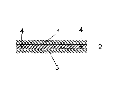
Figure 1 is a cross-sectional view of a tape according to an embodiment of the
invention; and
Figure 2 is a cross-sectional view of a tape according to another embodiment
of the invention.
The disadvantages of this concept are likewise complicated design, heat
losses, and irregular
temperature-control over the entire length.
Other applications (WO 92/11487, WO 85/04941, WO 2000/66934, WO 2000/66935 and
WO 2001/07824) concern the topic of thermal insulation as a passive method of
stabilization of
the temperature of the media. However, a problem here is the compressibility
of the foamed
structures often used. This can reduce the insulation effect at large depths
under water and at
the high external pressures associated therewith.
WO 2006/097765, WO 2006/090182, US 2008202616 and US 4 874 925 describe
another
heating method. This involves a multilayer pipe in which by way of example two
conductors are
present, embedded in a conductive layer and displaced by 180 with respect to
one another along
the pipe. Current flowing from one conductor to the other causes heating
within the conductive
layer. An important factor for uniform heating is connection to, or uniform
contact of the
conductor with, the conductive layer. The conductive layer has external
thermal and optionally
electrical insulation. An advisable or necessary feature is an additional
layer inside towards the
crude oil, for electrical insulation.
WO 2008/005829 describes heatable pipes in the automobile sector, where these
can comprise
an electrically conductive polymer layer; this layer acts as a resistance
heating system.
Some embodiments of the invention may provide a flexible pipe of multilayer
structure in which
the conveyed medium can be electrically heated, while the structure is not
significantly more
expensive. In some embodiments it should be possible to heat the pipe in a
targeted manner
only in the pipe sections where this is specifically required.
Some embodiments disclosed herein relate to a flexible pipe comprising the
following layers, from
the inside to the outside:
- an interior lining,
- at least one reinforcement layer, and
- optionally an exterior sheath,
CA 02776062 2012-05-04
201100176
4 -
an additional factor being that between two layers there is a further layer
made of a
wound tape which comprises the following layers:
a) a first exterior. layer (1) made of a plastics moulding composition that is
not
electrically conductive,
b) an intermediate layer (2) made of an electrically conductive plastics
moulding
composition of which the volume resistivity to IEC 60093 is in the range from
10's to
1010 S2m, preferably in the range from 10.2 to 108 SZm, particularly
preferably in the
range from 10'1 to 10' r 1m and with particular. preference in the range from
100 to 106
fm, where at least two metallic conductors (4) have been embedded into the
intermediate layer along the tape in such a way that, over the entire length,
they do
not touch one another, and also
c) a second exterior layer (3) made of a plastics moulding composition that is
not
electrically conductive.
The interior lining is usually a plastics pipe which provides a barrier to
escape of the
fluid conveyed. This pipe can, as a function of performance requirements,
comprise a
single layer or else can be composed of a plurality of layers made of
respectively
different moulding compositions. In this case it is by way of example a two-
layer,
three-layer, or four-layer system, or else in particular instances is composed
of even
more layers. Linings of this type are prior art. In another embodiment, the
interior
lining can also be composed of a corrugated, thin-walled metal pipe.
The reinforcement layer or layers is/are usually composed of helically
arranged steel
wires, steel profiles or steel tapes. The design of the said reinforcement
layers is
prior art. It is preferable that the structure of at least one of these
reinforcement
layers is such that it withstands the internal pressure, and that the
structure of at
least one other of these reinforcement layers Is such that it withstands
tensile forces.
There are usually more than two reinforcement layers present. Adjacent to the
reinforcement layers in most cases there is an exterior sheath, usually in the
form of
a pipe or flexible tube made of a thermoplastic moulding composition or made
of an
elastomer.
In one possible embodiment, there is a carcass on the interior side of the
interior
CA 02776062 2012-05-04
201100176
lining of the unbonded flexible pipe. These carcasses and design thereof are
prior
art. In another possible embodiment, the unbonded flexible pipe comprises no
carcass, especially when it is not intended for operation under high external
pressures.
5
Suitable materials for the electrically conductive plastics moulding
composition and
for the two plastics moulding compositions which are not electrically
conductive are,
independently of one another, moulding compositions by way of example based on
olefinic polymers, on polyamides, on fluoropolymers, on polyethylene 2,6-
naphthalate, on polybutylene 2,6-naphthalate, on polyphenyl sulphone, on
polyarylene ether ketone, on polyphenylene sulphide, or on a polyarylene ether
ketone/polyphenylene sulphide blend.
The olefinic polymer can firstly be a polyethylene, in particular a high-
density
polyethylene (HDPE), or an isotactic or syndiotactic polypropylene. The ,
polypropylene can be a homo- or copolymer, for example with ethylene or 1-
butene
as comonomer, and it is possible here to use either random or block
copolymers. The
polypropylene can moreover also have been impact-modified, for example as in
the
prior art by means of ethylene-propylene rubber (EPM) or EPDM. The
syndiotactic
polystyrene that can also be used according to the Invention can be produced
in a
known manner by metallocene-catalysed polymerization of styrene.
The polyamide can be produced from a combination of diamine and dicarboxylic
acid, from an oraminocarboxylic acid, or from the corresponding lactam. In
principle it
is possible to use any polyamide, for example PA6 or PA66. In one preferred
embodiment, the monomer units of the polyamide comprise on average at least 8,
at
least 9 or at least 10 carbon atoms. In the case of mixtures of lactams, it is
the
arithmetic average that is considered here. In the case of a combination of
diamine
and dicarboxylic acid, the arithmetic average of the number of carbon atoms of
diamine and dicarboxylic acid in this preferred embodiment must be at least 8,
at
least.9 or at least 10. Examples of suitable polyamides are: PA610 (which can
be
produced from hexamethylenediamine [6 carbon atoms] and sebacic acid [10
carbon
atoms], the average number of carbon atoms in the monomer units here therefore
being 8), PA88 (which can be produced from octamethylenediamine and 1,8-
octanedioic acid), PAB (which can be produced from caprylolactam), PA612,
PA810,
CA 02776062 2012-05-04
201100176
6
PA108, PA9, PA613, PA614, PA812, PA128, PA1010, PA10, PA814, PA148,
PA1012, PA11, PA1014, PA1212 and PA12. The production of the polyamides is
prior art. It is also possible, of course, to use copolyamides based on these
materials,
and it is also optionally possible here to make concomitant use of monomers
such as
caprolactam.
Advantageously, it is also possible to use, as polyamide, a semiaromatic
polyamide
in which from 5 to 100 mol% of the dicarboxylic acid content derives from
aromatic
dicarboxylic acid having from 8 to 22 carbon atoms and which has a crystallite
melting point Tm of at least- 260 C, preferably of at least 270 C and
particularly
preferably of at least 280 C. These polyamides are usually termed PPA. They
can be
produced from a combination of diamine and dicarboxylic acid, optionally with
addition of an co-aminocarboxylic acid or of the corresponding lactam.
Examples of
suitable types are PA66/6T, PA6/6T, PA6T/MPMDT (MPMD stands for 2-
methylpentamethylenediamine), PA9T, PA1OT, PA11T, PAI2T, PA14T and also
copolycondensates of these last types with an aliphatic diamine and with an
aliphatic
dicarboxylic acid or with an cry-aminocarboxylic acid or, respectively, a
lactam.
The moulding composition can comprise, alongside polyamide, further
components,
e.g. impact modifiers, other thermoplastics, plasticizers and other
conventional
additives. The only requirement is that the polyamide forms the matrix of the
moulding composition.
The fluoropolymer can by way of example be a polyvinylidene fluoride (PVDF),
an
ethylene-tetrafluoroethylene copolymer (ETFE), an ETFE modified with the aid
of a
tercomponent such as propene, hexafluoropropene, vinyl fluoride or vinylidene
fluoride (for example EFEP), an ethylene-chlorotrifluoroethylene copolymer
(E-CTFE), a polychiorotrifluoroethylene (PCTFE), a chlorotrifluoroethylene-
perfluorinated alkyl vinyl ether-tetrafluoroethylene copolymer (CPT), a
tetrafluoroethylene-hexafluoropropene copolymer (FEP) or a tetrafluoroethylene-
perfluorinated alkyl vinyl ether copolymer (PFA). It is also possible to use
copolymers
based on vinylidene fluoride which comprise up to 40% by weight of other
monomers, examples being trifluoroethylene, chiorotrifluoroethylene, ethylene,
propene and hexafluoropropene.
CA 02776062 2012-05-04
201100176
7 ,
Polyphenyl sulphone (PPSU) is produced by way of example by Solvay Advanced-
Polymers under trade mark Radel . It can be produced by nucleophilic
substitution
from 4,4'-dihydroxybiphenyl and 4,4'-dihydroxydiphenyl sulphone. Another
particular
suitable material is a PPSU/fluoropolymer blend, for example a PPSU/PTFE
blend.
The polyarylene ether ketone which can likewise be used comprises units of the
formulae
(-Ar-X-) and (-Ar-Y-),
where Ar and Ar' are a divalent aromatic moiety, preferably 1,4-phenylene,
4,4'-biphenylene, or else 1,4-, 1,5- or 2,6-naphthylene. X is an electron-
withdrawing
group, preferably carbonyl or sulphonyl, while Y is another group, such as 0,
S, CH2,
isopropylidene or the like. At least 50%, preferably at least 70% and
particularly
preferably at least 80% of the groups X here are a carbonyl group, while at
least
50%, preferably at least 70% and particularly preferably at least 80% of the
groups Y
are composed of oxygen.
In the preferred embodiment, 100% of the groups X are composed of carbonyl
groups and 100% of the groups Y are composed of oxygen. In this embodiment,
the
polyarylene ether ketone can by way of example be a polyether ether ketone
(PEEK;
formula I), a polyether ketone (PEK; formula II), a polyether ketone ketone
(PEKK;
formula III) or a polyether ether ketone ketone.(PEEKK; formula IV), but other
arrangements of the carbonyl groups and oxygen groups are naturally also
possible.
O O O O O C
II
I
n
O O O C II
In
CA 02776062 2012-05-04
201100176
8
Q o D-C -c
II )li
0 0
n
O O. O O O C O C IV
II N
0 0
n
The polyarylene ether ketone Is semicrystalline, and this is seen by way of
example
in the DSC analysis where a crystallite melting point T. is observed, the
order of
magnitude of which is in most instances around 300 C or thereabove.
The polyphenylene sulphide comprises units of the formula
(-C6H4-S-);
and it is preferably composed of at least 50% by weight of the said units, or
at least
70% by weight or at least 90% by weight. The remaining units can be those
stated
above for the case of the polyarylene ether ketone, or tri- or tetra-
functional
branching units which result from the concomitant use of, for example,
trichlorobenzene or tetrachlorobenzene during synthesis. Polyphenylene
sulphide is
available commercially in a wide variety of types or moulding compositions.
In the case of the polyarylene ether ketone/polyphenylene sulphide blends, the
two
components can be present in any conceivable mixing ratio, and the range of
constitution therefore continuously covers the entire range from pure
polyarylene
ether ketone to pure polyphenylene sulphide. The blend generally comprises at
least
0.01 % by weight of polyarylene ether ketone and, respectively, at least 0.01
% by
weight of polyphenylene sulphide.
CA 02776062 2012-05-04
201100176
9
The plastics moulding compositions-can comprise the usual auxiliaries and
additives,
and also optionally other polymers, an example in the case of the polyarylene
ether
ketone being fluoropolymers, such as PFA (a copolymer of tetrafluoroethylene
and
perfluorinated vinyl methyl ether), polyamide, polyetherimide, LCP, such as
liquid-
crystalline polyesters, polysuiphone, polyether sulphone, polyphenyl sulphone,
polybenzimidazole (PBI) or other high-temperature-resistant polymers, and an
example in the case of the polyphenylene sulphide being copolymers and,
respectively, terpolymers of ethylene with polar comonomers, and in the case
of the
semiaromatic polyamide an aliphatic polyamide. The polyamide moulding
composition can by way of example also comprise a hydrolysis stabilizer, a
plasticizer and, respectively, impact modifiers. The moulding composition can
moreover comprise a lubricant, such as molybdenum disulphide, hexagonal boron
nitride or PTFE. The proportion of the main polymers, or else, in the
preferred case,
the proportion of olefinic polymer, polyamide, fluoropolymer, polyphenyl
sulphone,
polyarylene ether ketone, polyphenyiene sulphide or polyarylene ether
ketone/polyphenylene sulphide blend in the moulding composition is at least
50% by
weight, preferably at least 60% by.weight, particularly preferably at least
70% by
weight, with particular preference at least 80% by weight and very
particularly
preferably at least 90% by weight.
The electrical conductivity of the intermediate layer according to'b) is
achieved in a
known manner, for example through addition of conductive or other carbon
black,
graphite powder and/or carbon nanotubes (CNTs) or graphite fibrils.
The tape can, if desired, also comprise further layers alongside the layers
according
to a), b) and c), for example an adhesion promoter layer between the layers
according to a) and b) and/or an adhesion promoter layer between the layers
according to b) and c).
The cross-sectional area of the tape can by way of example be of rectangular
or
rounded shape.
At the edges of the tape, the individual layers can have uncovered edges
(Figure 1),
or the layers according to a) and c) can have been bonded to one another at
that
CA 02776062 2012-05-04
201100176
location (Figure 2), in order to achieve the best possible electrical
insulation in
relation to the reinforcement layers.
The metallic conductors embedded into the layer according to b) can be
connected to
5 a source of electrical current. The potential difference then present
between the
individual conductors causes a.current to flow through the electrically
conductive
intermediate layer, the said layer therefore functions as resistance heating
system.
The voltage applied here can be direct voltage or alternating voltage. In
order to
reduce the risk of failure, it can be advantageous to have more than two
metallic
10 conductors embedded into the Intermediate layer according to b), for
example three,
four, five or six. The metallic conductors must be corrosion-resistant with
regard to
the conveyed fluid and its constituents.
The thickness of the tape is usually in the range from 0.2 to 5 mm, preferably
in the
range from 0.4 to 5 mm and particularly preferably in the range from 0.5 to 4
mm.
The thickness of the intermediate layer according to b) here is generally in
the range
from 0.1 to 3 mm, preferably in the range from 0.2 to 2.5 mm and particularly
preferably in the range from 0.3 to 2 mm, while the thickness of each of the
two
exterior layers according to a) and c) is generally in the range from 0.05 to
1.5 mm,
preferably in the range from 0.1 to 1 mm and particularly preferably in the
range from
0.1 to 0.5 mm.
The width of the tape depends on the diameter of the pipe. Usual widths are in
the
range from about 20 mm to about 700 mm, preferably in the range from about 30
mm
to about 500 mm and particularly preferably in the range from about 40 mm to
about
300 mm.
The tape is wound helically under tension onto a layer situated further
inwards, and
this winding can be carried out either with edges abutted or with overlap. In
the latter
case, the overlapping locations of the tape can be fused after the winding
process.
This can be achieved either by hot gas welding, by contact with a heating
element,
by means of a (gas) flame or by irradiation with electromagnetic radiation in
the UV,
visible or IR spectral range. In principle, spot welding is sufficient to fix
the tape;
however, preference is given to continuous production of an uninterrupted
welded
seam. Another possibility, of course, is that the full surface of the tape is
welded in
CA 02776062 2012-05-04
201100176
11
the overlapping regions. For the fusion process it is advantageous for the
softening
range of the moulding composition in the layers according to a) and c) to be
lower
than the softening range of the moulding composition in the layer according to
b).
In order to reduce the risk of failure, it is also possible. to wind,
alongside one another
or over one another, a plurality of tapes, each of. which possesses its own
electrical
circuit. It is moreover possible that the flexible pipe also possesses a
plurality of such
layers made of wound tape and separated from one another by a reinforcement
layer.
The layer made of wound tape can also simultaneously function as an anti-wear
layer. In the prior art, anti-wear tapes are placed between the reinforcement
layers
made of steel, in order to prevent abrasion of the reinforcement layers. The
primary
result of this is abrasion of the tape. This abrasion must where appropriate
be
considered during design, in order to ensure that the electrically conductive
intermediate layer is insulated over the entire lifetime of the flexible pipe.
For the
layers according to a) and c), it is therefore preferable to use moulding
compositions
which have particularly good tribological properties.
When the moulding composition of the layer according to b) comprises, as
electrically
conductive additive, (conductive) carbon black, the heating system can utilize
the
PTC (positive temperature coefficient) effect. This effect provides an
intrinsic safety
feature, since it restricts temperature increase at constant voltage, because
conductivity falls as the system becomes hotter. This can prevent thermal
degradation of the pipe or of the medium to be transported.
According to the invention, it is also possible that the tape is placed only
in specific
sections of the pipe. It is possible to design this to be conductive in the
region where
specific heating is required, and to introduce, instead of this, in other
regions of the
pipe, by way of example a conventional anti-wear tape.
The flexible pipe can optionally comprise, alongside the layers described
here,
further layers, for example unidirectionally reinforced or textile-reinforced
polymer
layers, and it is possible here to use carbon fibre reinforcement with good
thermal
conductivity, or an externally situated thermal insulation layer.
CA 02776062 2012-05-04
201100176
12
With the aid of the invention it is possible to heat the pipe over its entire
length or in
selected sections, in order to prevent precipitation. Thermal degradation of
the pipe
system and of the transported medium can thus be avoided. Technical
realization is
simple, since no complicated additional -technical parts are needed, and the
structure
per se of the pipe is not altered. The pipe of the invention can therefore be
heated
efficiently to the extent that it can also be used for conveying oil in cold
regions, for
example in the Arctic. Another possibility is use over long distances in deep-
sea
locations, where the conveyed medium is prevented from falling below the
critical
temperature discussed above.