Language selection

Search

Patent 2776086 Summary

Third-party information liability

Some of the information on this Web page has been provided by external sources. The Government of Canada is not responsible for the accuracy, reliability or currency of the information supplied by external sources. Users wishing to rely upon this information should consult directly with the source of the information. Content provided by external sources is not subject to official languages, privacy and accessibility requirements.

Claims and Abstract availability

Any discrepancies in the text and image of the Claims and Abstract are due to differing posting times. Text of the Claims and Abstract are posted:

  • At the time the application is open to public inspection;
  • At the time of issue of the patent (grant).
(12) Patent: (11) CA 2776086
(54) English Title: HOLLOW CORE AIRFOIL STIFFENER RIB
(54) French Title: BANDE RIGIDE POUR AILE A AME CREUSE
Status: Granted
Bibliographic Data
(51) International Patent Classification (IPC):
  • F01D 5/18 (2006.01)
(72) Inventors :
  • DUROCHER, ERIC (Canada)
  • DEMERS, MAXIME (Canada)
(73) Owners :
  • PRATT & WHITNEY CANADA CORP. (Canada)
(71) Applicants :
  • PRATT & WHITNEY CANADA CORP. (Canada)
(74) Agent: NORTON ROSE FULBRIGHT CANADA LLP/S.E.N.C.R.L., S.R.L.
(74) Associate agent:
(45) Issued: 2020-06-30
(22) Filed Date: 2012-05-04
(41) Open to Public Inspection: 2013-02-24
Examination requested: 2017-04-12
Availability of licence: N/A
(25) Language of filing: English

Patent Cooperation Treaty (PCT): No

(30) Application Priority Data:
Application No. Country/Territory Date
13/216613 United States of America 2011-08-24

Abstracts

English Abstract

A stiffener rib for a non-cooled, hollow core airfoil of a turbine blade is described. The stiffener rib is constituted by an elongated sold metal piece dimensioned for securement in a hollow region of a core portion of the airfoil. The stiffener rib is shaped and oriented upwards from a leading edge of the airfoil at a predetermined calculated angle to minimize mode 2 deformation of the blade at a trailing edge thereof while improving the rigidity of the turbine blade.


French Abstract

Une bande rigide pour un profil aérodynamique non refroidi à âme creuse dune aube de turbine est décrite. La bande rigide est constituée dune pièce de métal solide étirée dont les dimensions sont prévues pour un arrimage dans un endroit creux de la partie centrale dun profil aérodynamique. La bande rigide est dessinée et orientée vers le haut à partir dun bord dattaque du profil aérodynamique selon un angle prédéterminé qui est calculé de façon à minimiser le mode 2 de déformation de laube sur son bord de fuite tout en améliorant la rigidité de laube de turbine.

Claims

Note: Claims are shown in the official language in which they were submitted.


CLAIMS:

1. A gas turbine engine blade comprising an airfoil extending from a
platform to a tip
between a leading edge and a trailing edge, said airfoil having a hollow core
portion adjacent
said leading edge and spaced-apart from said trailing edge in in a chordwise
direction, the hollow
core portion extending from the platform to the tip, and a stiffener rib
provided in the hollow
core portion of said airfoil and extending across a thickness of the airfoil
between opposed side
walls of the hollow core portion, the stiffener rib being positioned closer to
the leading edge than
the trailing edge in the chordwise direction, the stiffener rib having an
elongated cross-section
including a longitudinal length L greater than a width W, the stiffener rib
having a longitudinal
axis which is angled to have a radial upward component and an axial component
in a direction
away from the leading edge of the airfoil, the longitudinal axis of the
stiffener rib extending
through the trailing edge at a location adjacent to a trailing edge tip corner
where the trailing
edge meets the tip of the blade.
2. The blade defined in claim 1, wherein the stiffener rib is positioned
and oriented to
minimize mode 2 deformation at the trailing edge, and wherein the stiffener
rib extends at about
200 to 60° degrees from a reference axis extending transverse to a tip
axis of the leading edge.
3. The blade defined in claim 2, wherein the stiffener rib extends at about
33° degrees from
the reference axis.
4. The blade defined in claim 1, wherein said stiffener rib is an elongated
hollow
rectangular rib having opposed convex end edges.
5. The blade defined in claim 1, wherein the distance T between the
longitudinal axis of the
stiffener rib and an axis parallel thereto and extending through the trailing
edge tip corner is
equal to or less than 0.275 inches.
6. The blade defined in claim 1, wherein the stiffener rib is spaced from
the leading edge by
a distance S of about 0.175~0.075 inches.

- 6 -


7. A stiffener rib in combination with a non-cooled, hollow core airfoil of
a turbine or
compressor blade, said stiffener rib being constituted by an elongated solid
metal piece
positioned in a hollow region of a hollow core portion of said airfoil
adjacent to a leading edge of
the airfoil and spaced-apart from a trailing edge of the airfoil in a
chordwise direction, and said
stiffener rib being shaped and oriented upwards from a leading edge of said
airfoil at a
predetermined calculated angle to minimize mode 2 deformation of the blade at
a trailing edge
thereof, and wherein the stiffener rib is positioned closer to the leading
edge than the trailing
edge in a chordwise direction.
8. The combination as claimed in claim 7, wherein said predetermined
calculated angle is in
the range of from about 20° to 60° degrees from a reference axis
extending transverse to a tip
axis of said leading edge.
9. The combination as claimed in claim 8, wherein said predetermined angle
is equal to
about 33° degrees.
10. The combination as claimed in claim 7, wherein said stiffener rib
extends across the
thickness of said hollow core airfoil and secured between opposed side walls
of said airfoil.
11. The combination as claimed in claim 7, wherein said stiffener rib is
dimensioned to move
the natural frequency mode 2 out of running range of said turbine blade.
12. The combination as claimed in claim 11, wherein said stiffener rib is
dimensioned in
length to tune the frequency of said turbine blade and to permit the flow of
air throughout said
hollow core.
13. The combination as claimed in claim 7, wherein said stiffener rib is an
elongated
rectangular rib haying opposed convex end edges.
14. A method of minimizing deflection of a trailing edge of a non-cooled
hollow core airfoil
subject to mode-2 deformation, comprising the steps of:

- 7 -


i) calculating by dynamic analytical model for mode 2 the dimension and
orientation of a stiffener rib for location in a hollow region of a core
portion of said hollow core
airfoil adjacent to a leading edge of the airfoil and spaced-apart from the
trailing edge of the
airfoil in a chordwise direction, and
ii) securing said stiffener rib across opposed side walls of said airfoil
and oriented
angularly upwards from a leading edge of said airfoil at a predetermined angle
to minimize
deflection of said blade at said trailing edge in the running range of said
airfoil and improve the
rigidity thereof, the stiffener rib being positioned closer to the leading
edge than the trailing edge
in a chordwise direction.
15. The method as claimed in claim 14, wherein said step (ii) comprises
securing said
stiffener rib at a predetermined calculated angle in the range of from about
20° to 60° degrees
from a reference axis extending transverse to a tip axis of said leading edge.
16. The method as claimed in claim 15, wherein said calculated angle is
approximately 33°
degrees.

- 8 -

Description

Note: Descriptions are shown in the official language in which they were submitted.

Sorry, the description for patent document number 2776086 was not found. Text is not available for all patent documents. The current dates of coverage are on the Currency of Information  page
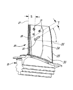
Representative Drawing
A single figure which represents the drawing illustrating the invention.
Administrative Status

For a clearer understanding of the status of the application/patent presented on this page, the site Disclaimer , as well as the definitions for Patent , Administrative Status , Maintenance Fee  and Payment History  should be consulted.

Administrative Status

Title Date
Forecasted Issue Date 2020-06-30
(22) Filed 2012-05-04
(41) Open to Public Inspection 2013-02-24
Examination Requested 2017-04-12
(45) Issued 2020-06-30

Abandonment History

There is no abandonment history.

Maintenance Fee

Last Payment of $263.14 was received on 2023-12-18


 Upcoming maintenance fee amounts

Description Date Amount
Next Payment if small entity fee 2025-05-05 $125.00
Next Payment if standard fee 2025-05-05 $347.00

Note : If the full payment has not been received on or before the date indicated, a further fee may be required which may be one of the following

  • the reinstatement fee;
  • the late payment fee; or
  • additional fee to reverse deemed expiry.

Patent fees are adjusted on the 1st of January every year. The amounts above are the current amounts if received by December 31 of the current year.
Please refer to the CIPO Patent Fees web page to see all current fee amounts.

Payment History

Fee Type Anniversary Year Due Date Amount Paid Paid Date
Application Fee $400.00 2012-05-04
Maintenance Fee - Application - New Act 2 2014-05-05 $100.00 2014-03-14
Maintenance Fee - Application - New Act 3 2015-05-04 $100.00 2015-03-30
Maintenance Fee - Application - New Act 4 2016-05-04 $100.00 2016-04-22
Request for Examination $800.00 2017-04-12
Maintenance Fee - Application - New Act 5 2017-05-04 $200.00 2017-04-21
Maintenance Fee - Application - New Act 6 2018-05-04 $200.00 2018-04-23
Maintenance Fee - Application - New Act 7 2019-05-06 $200.00 2019-04-18
Final Fee 2020-04-22 $300.00 2020-04-15
Maintenance Fee - Application - New Act 8 2020-05-04 $200.00 2020-04-23
Maintenance Fee - Patent - New Act 9 2021-05-04 $204.00 2021-04-22
Maintenance Fee - Patent - New Act 10 2022-05-04 $254.49 2022-04-21
Maintenance Fee - Patent - New Act 11 2023-05-04 $263.14 2023-04-19
Maintenance Fee - Patent - New Act 12 2024-05-06 $263.14 2023-12-18
Owners on Record

Note: Records showing the ownership history in alphabetical order.

Current Owners on Record
PRATT & WHITNEY CANADA CORP.
Past Owners on Record
None
Past Owners that do not appear in the "Owners on Record" listing will appear in other documentation within the application.
Documents

To view selected files, please enter reCAPTCHA code :


To view images, click a link in the Document Description column. To download the documents, select one or more checkboxes in the first column and then click the "Download Selected in PDF format (Zip Archive)" or the "Download Selected as Single PDF" button.

List of published and non-published patent-specific documents on the CPD .

If you have any difficulty accessing content, you can call the Client Service Centre at 1-866-997-1936 or send them an e-mail at CIPO Client Service Centre.


Document
Description 
Date
(yyyy-mm-dd) 
Number of pages   Size of Image (KB) 
Final Fee / Change to the Method of Correspondence 2020-04-15 5 157
Representative Drawing 2020-05-28 1 7
Cover Page 2020-05-28 1 32
Abstract 2020-06-29 1 6
Drawings 2020-06-29 2 20
Description 2020-06-29 5 131
Abstract 2012-05-04 1 6
Description 2012-05-04 5 131
Claims 2012-05-04 3 49
Drawings 2012-05-04 2 20
Representative Drawing 2013-02-18 1 9
Cover Page 2013-03-06 1 35
Examiner Requisition 2018-05-28 3 217
Amendment 2018-11-09 5 216
Claims 2018-11-09 3 113
Examiner Requisition 2018-12-20 3 164
Assignment 2012-05-04 4 63
Amendment 2019-06-18 3 116
Claims 2019-06-18 3 113
Request for Examination 2017-04-12 2 72