Note: Descriptions are shown in the official language in which they were submitted.
CA 02776111 2012-04-26
1
SEALING SHEET FOR USE TO CLOSE A CONTAINER-DEFINING SHEET
Background of the invention
The present invention relates to an improvement to a sealing sheet used to
close a
plurality of containers formed in a container-defining sheet for the storage
of pills.
Brief description of the prior art
It is of common practice in the pharmaceutical field to prepare sets of
individual containers containing pills and/or tablets to be administered to a
patient.
Each of these containers contains pills and/or tablets that the patient has to
take
together at the same time during the day over a given period of time
(preferably one
week).
To prepare such sets of individual pill containers for use by a patient, it is
also
of common practice to use a sheet of plastic material in which a plurality of
cavities
are embossed. Each of these cavities defines a small upwardly opened container
that can be filled with pills. After filling, all the containers are closed by
means of a
sealing sheet on which all desirable indications can be printed, like the
patient's
name, the date and hour of administration, etc. As it can be understood, the
indications are printed and formated onto the sealing sheet so that each group
of
information referring to a given container is positioned in regard to said
container.
Tearing lines are provided on both the container-defining sheet and the
sealing
sheet to permit easy separation of the individual pill containers.
For further information as to the structure, manufacture and use of such sets
of individual pill containers, reference can be made to U.S. patent no.
5,788,079 and
its Canadian counterpart no. 2,207,045 which both name the present inventor.
CA 02776111 2012-04-26
2
As disclosed in the above mentioned US and Canadian patents naming the
present inventor, the sealing sheet used to close the containers can be made
of
paper or similar material and be glued onto the container-defining sheet. For
this
purpose, the sealing sheet comprises a top layer having a lower surface
covered
with a pressure sensitive adhesive glue and a bottom layer having an upper
surface
detachably fixed to the lower surface of the top layer by means of the
adhesive glue.
The bottom layer is peelable from the lower surface of the top layer to allow
fixation
of it onto the top surface of the container-defining sheet. Advantageously,
this
bottom layer has tearing lines punched into it in such a manner and position
as to
leave parts of it glued onto the bottom surface of the top layer in the form
of a
number of bottom pieces equal to the given number of cavities made in the
container-defining sheet when the sealing sheet is peeled off. Each of these
bottom
pieces are shaped, sized and positioned so as to extend over a corresponding
cavity of the container-defining sheet when the sealing sheet is properly
applied to
and glued on the flanges of the top surface of the container-defining sheet.
These
bottom pieces thus prevent the pill(s) stored in each of the containers from
coming
into contact with the adhesive glue.
As other examples of such a sealing sheet, reference can be made to Canadian
patent no. 2,538,623 and US patents nos. 6,382,420, 7,543,709 and 7,762,399,
all
of which also name the present inventor.
However, a problem that still remains in the sealing sheets presently in use
and
disclosed in the abovementioned patents, is that there is often not enough
space
onto the upper surface of the top layer of the container defining-sheet, to
print all the
information required regarding the content of each container.
Summary of the invention
The object of the present invention is to solve the above mentioned problem.
CA 02776111 2012-04-26
3
For this purpose, the present invention provides an improvement to a sealing
sheet
for use to close a container-defining sheet having a top surface comprising a
given
number of spaced apart cavities embossed therein, each of the cavities being
upwardly opened and thus defining a container that is surrounded by a flange
that is
part of the top surface of the container-defining sheet.
Like the sealing sheets disclosed in the above mentioned Canadian and US
patents, the sealing sheet according to the invention basically comprises:
- a top layer having an upper surface and a lower surface, said lower
surface
being covered with a pressure sensitive adhesive glue; and
- a bottom layer having an upper surface detachably fixed to the lower
surface of
the top layer by means of said pressure sensitive adhesive glue, said bottom
layer
being peelable from the lower surface of the top layer to allow fixation of
the sealing
sheet onto the top surface of the container-defining sheet in order to close
the
containers defined in the same.
The top layer has pairs of tearing lines punched therein. Each of said pairs
of
tearing lines is adjacent to one of the cover pieces extending from one side
of said
adjacent cover piece towards at least one adjacent corner of the bottom piece
of the
cover piece, in order to facilitate peeling of the bottom piece and of the
corresponding part of the cover piece from the corresponding container and
thus to
give access to the element(s) stored in it.
The bottom layer also has tearing lines punched into it in such a manner and
position as to leave parts of the bottom layer glued onto the bottom surface
of the
top layer in the form of a number of bottom pieces equal to the given number
of
cavities made in the container-defining sheet when said sealing sheet is
peeled off.
Each of said bottom pieces is shaped, sized and positioned so as to extend
over a
corresponding cavity of the container-defining sheet when the sealing sheet is
CA 02776111 2012-04-26
4
properly applied to and glued on the flanges of the top surface of the
container-
defining sheet. Said bottom pieces thus prevent any element stored in the
containers from coming into contact with the adhesive glue,.
Advantageously, the container-defining sheet may comprise recesses embossed
therein so as to extend adjacent to the one side of each of the cover pieces
from
which extend the tearing lines allowing peeling of the corresponding bottom
piece
from the corresponding container. These recesses are U-shaped so as to give
easy
access to a finger and thus facilitate such a peeling.
As it is disclosed in US patent no. 7,543,709, the tearing lines of the bottom
layer of
the sealing sheet may also be devised so as to provide each of the bottom
pieces
with a small pulling tab projecting from one edge of the bottom piece, in such
a
manner that once the sealing sheet is glued on top of the container defining-
sheet,
the pulling tab extending at a short a distance away from the cavity of the
corresponding container towards the adjacent recess embossed therein, such
facilitating again peeling of the bottom piece from the container. The tearing
lines of
the bottom layer of the sealing sheet may also be devised so as to provide
each of
said bottom pieces with an extension opposite to the edge from which projects
the
pulling tab.
As aforesaid, the basic structure disclosed hereinabove of the sealing sheet
according to the invention is known per se and disclosed in the above
mentioned
patents.
As a matter of fact, the present invention lies in an improvement to this
basic
structure of the sealing sheet.
CA 02776111 2012-04-26
This improvement essentially consists in an additional layer that may be glued
onto
the upper surface of the top layer in such a manner as to have one part
foldably
attached to the sealing piece of each individual pill container once such a
pill
container is separated. It is thus possible to print additional information as
to the
contained of the corresponding pill container and its use, which can be read
up,
down or up and down of the part of the additional layer attached to the
sealing
piece, just by folding it.
So, the present invention is directed to a sealing sheet as disclosed herein
above,
which further comprises an additional layer having an upper part and a lower
part
attached to each other, said upper part having tearing lines punched into it
in such a
manner and position as to match with the tearing lines of the top layer of the
sealing
sheet and thus form an additional element on the upper surface of the top
layer on
each of said container, said bottom part having peelable bands that can be
removed
to allow gluing of each of said additional elements onto the upper surface of
the top
layer of each container on one side of it so as to allow said additional
elements to
be folded up, said bottom part also having tearing lines positioned to match
those of
the top part of the additional layer but except on the peelable bands,
whereby, in
use, additional information may be printed onto one or both sides of said
additional
layer to add information to what is located in each of the containers, such
added
information as well as the information already printed on the upper surface of
the
top layer being easily accessible by merely folding up the additional element
of each
of the container.
Preferably, the additional layer has opposite side borders that may be teared
off in
order to reduce the width of said additional layer and give easier access to
the
pulling tabs of the bottom pieces.
CA 02776111 2012-04-26
6
If needs be, the sealing sheet may also comprise another additional layer
similar to
the first one and attached in the same way to it and on which further
additional
information may be printed.
Of course, the sealing sheet including its additional layer, and the container-
defining
sheet are provided with positioning means to ensure proper positioning of both
of
them with respect to each other during installation and thus exact
superimposition of
the bottom pieces of the sealing sheet on top of the corresponding cavities,
and
exact superposition of the tearing lines of the top layer of the sealing sheet
with the
tearing lines of container-defining sheet.
The invention and its advantages will be better understood upon reading the
following non restrictive description of a preferred embodiment of it, made
with
reference to the accompanying drawings.
Brief description of the drawings
Figure 1 is an exploded perspective view of a kit comprising a recessed
support, a
container-defining sheet and the bottom, top and additional layers of a
sealing sheet
of a set of individual pill container according to a preferred embodiment of
the
invention;
Figure 2 is bottom perspective view of the additional layer of the sealing
sheet
shown in Figure 1, illustrating however the border and bottom sides of it may
be
teared;
Figure 3 is a bottom perspective of the additional layer shown in Figure 2,
illustrating
the location of the pealable bands and how they can be removed to allow gluing
of
the same on the upper surface of the top layer of the sealing sheet;
CA 02776111 2012-04-26
7
Figure 4 is a perspective view illustrating how the additional layer can be
applied for
gluing onto the upper surface of the top layer;
Figure 5 is a perspective view of the container defining sheet after its
closing with
the sealing sheet and its removal from the recessed support used for their
assembly, said figure also illustrating the tearing of the upper portion of
the
additional layer used for its positioning;
Figure 6 is a perspective view of the upper portion of the additional layer
after it has
been teared and how a peelable band made on it can be removed to allow its
gluing
onto the upper portion of the sealing sheet, if such is wanted;
Figure 7 is a perspective view illustrating how the upper portion of the
additional
layer can be positioned and glued onto the sealing sheet;
Figure 8 is a perspective view of the container-defining sheet closed with the
sealing
sheet with the upper portion of the additional layer glued on it;
Figures 9a, 9b and 9c are perspective views of a container obtained after its
separation, showing how the additional layer glued on it can be folded, and
giving
an example of information that can be provided onto it and on the upper
surface of
the top layer of the sealing sheet before the same is pulled; and
Figure 9d is a perspective view similar to the one of figure 9b, but
illustrating the
container with two additional layers glued on it to increase the place where
information may be printed.
CA 02776111 2012-04-26
8
Detailed description of the invention
As indicated hereinabove, the present invention relates to an improvement made
to
a sealing sheet for use to seal a container-defining sheet like those
especially
devised to form sets of individual pill containers for use in pharmacies or
hospitals.
As aforesaid, Figure 1 illustrates a kit comprising a recessed support 1, a
container-
defining sheet 3 and a sealing sheet 5 intended to be attached on top of the
container-defining sheet 3, as disclosed in US patent n 7,543,709.
The container-defining sheet 3 is preferably made of a plastic material and
has a top
surface comprising a given number of spaced apart cavities 7 embossed therein.
Each cavity 7 is upwardly opened and thus defines a container 9 which is
surrounded by a flange 11. Each of the flanges 11 which is not directly
adjacent to
one external side of the container-defining sheet 3 is provided with a
centrally
positioned tearing line 13 so as to make it possible to detach each of the
containers
9 from the other containers adjacent to it and thus from the container-
defining sheet
3 whenever desired.
The purpose of the recessed support 1 mentioned hereinabove which is
preferably
made of rigid plastic material, is actually to receive, hold and support one
or more of
said container-defining sheet 3. For this purpose, it comprises on its top
surface, a
plurality of recesses 43 that are equal in number to the number of containers
9
embossed on the container-defining sheet 3, and are positioned, shaped and
sized
to receive these containers 9. In the illustrated embodiment, the recessed
support 1
also comprises a pair of holes 47 located on opposite sides of its top surface
close
to the side where are located the upwardly projecting protuberances 45. Such
is
particularly interesting in that such holes 47 allow the user to insert
his/her fingers
below the container-defining sheet and thus facilitate removal of the same.
CA 02776111 2012-04-26
9
The sealing sheet 5 is preferably made of paper and devised to be positioned
on top
of the top surface of the container-defining sheet 3 in order to close each of
the
CO ntainers.
As it is illustrated, the sealing sheet 5 comprises a top layer 15 which has a
lower
surface 19 that is covered with a pressure-sensitive adhesive glue. The
sealing
sheet 5 also comprises a bottom layer 21 that is detachably fixed to the lower
surface 19 of the top layer 15 by means of the adhesive glue. The bottom layer
21 is
devised to be peelable from the lower surface 19 of the top layer 15 in order
to allow
fixation of the sealing sheet 5 on to the top surface of the container-
defining sheet 3
and thus close all the containers 9 on said sheet 3 made in this sheet 3.
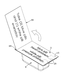
As it is also shown in Figure 1, the bottom layer 21 of the sealing sheets has
tearing
lines 23 that are punched into it in such a manner and position as to leave
parts of
the bottom layer 21 glued onto the bottom surface 19 of the top layer 15 in
the form
of a number of bottom pieces 25 equal to the number of cavities 7 made in the
container-defining sheet 3 when the sealing sheet 5 is peeled off. Each of the
bottom pieces 25 is shaped, sized and positioned so as to extend over a
corresponding cavity 7 of the container-defining sheet 3 when the sealing
sheet is
properly applied to and glued on the flanges 11 located on the top surface of
the
container-defining sheet 3. As a result, these bottom pieces 25 prevent any
element
like pills stored in the containers 9, from coming into contact with the
adhesive glue
that was originally applied to all the adjacent surfaces of the top and bottom
layers
15 and 21 of the sealing sheet 5. As to the particular position and protective
effect of
each of the bottom pieces 25, reference can be made to Figure 9c of the
drawings.
As it is illustrated, the tearing lines 23 of the bottom layer 21 of the
sealing sheet 5
are advantageously devised to provide each of the bottom pieces 25 with a
small
10
pulling tab 31 projecting from one edge of the bottom piece, hereinafter
called "front
edge", in such a manner that, once the sealing sheet 5 is glued on top of the
container-defining sheet 3, this pulling tab 31 extends at a short distance
away from
the cavity 7 of the corresponding container 9 towards an adjacent recess 33
embossed therein. Such advantageously facilitates peeling of the bottom piece
25
from the container 9.
The recesses 33 are preferably U-shaped, so as to give easy access to a finger
and
thus facilitate such a peeling. Such substantially facilitates access to the
content of
each container 9.
As it is also shown in Figure 1, the top layer 15 of the sealing sheet 5 has
tearing
lines 27 punched therein in such a manner and position as to be in line with
the
tearing lines 13 of the container-defining sheet 3, in order to allow the top
layer 15,
once glued onto the flanges 11 on top of the container-defining sheet 3, to be
splitted into a number of cover pieces equal to the number of containers 9.
Such is
actually necessary to allow detachment of each of the containers 9 from the
container-defining sheet 3 while keeping the so-detached containers closed.
The top layer 15 of the sealing sheet 5 also has pairs of tearing lines 29
punched
therein, each of said pairs being adjacent to one of the cover pieces
extending from
one side of the corresponding cover piece towards one adjacent side of the
corresponding bottom piece 25.
The purpose of these tearing lines 29 is to facilitate peeling of the bottom
piece 25
and of the corresponding part of the cover piece from the corresponding
container
and thus facilitate access to the elements stored therein.
CA 2776111 2018-04-25
CA 02776111 2012-04-26
11
For further information concerning the structure of the above sealing sheet,
reference can be made inter alia to the above mentioned US patent no.
7,543,709.
As aforesaid, the present invention lies in that the above mentioned sealing
sheet 5
is improved in that it also comprises an additional layer 51 having an upper
part 53
and a lower part 55 attached to each other. The upper part 53 has tearing
lines 57
punched into it in such a manner and position as to match with the tearing
lines 27
of the top layer 15 of the sealing sheet and thus form an additional element
59 on
the upper surface of the top layer on each of the containers 9, as shown in
Figures
9a to 9d. As shown also in Figures 2 and 3, the bottom part 55 of the
additional
layer has peelable bands 61 that can be removed to allow gluing of each of the
additional elements 59 onto the upper surface of the top layer 15 of each
container
9 on one side of it so as to allow said additional element 59 to be folded up
as
shown in Figure 9b and 9c. Of course, for this purpose, the bottom part of the
additional layer 51 also has tearing lines 63 positioned to match those 57 of
the top
part of the additional layer, but not on the peelable bands.
In practice, the positioning of the peelable bands 61 has to be made in such a
manner that the portion 65 of the additional element 59 glued onto one side of
each
container 9, be actually opposite to the side of said container 9 where are
located
the tearing lines 29 of the top layer 15 of the sealing sheet.
As shown again in Figures 9a to 9c, additional information may be printed onto
one
or both sides of the additional layer to add information to what is located in
each of
the containers, such added information as well as the information already
printed on
the upper surface of the top layer being easily accessible by merely folding
up the
additional element 59 of each of the container 9.
12
As is better shown in Figure 2, the additional layer 51 preferably has
opposite side
borders 67 that may be teared off in order to reduce its width and give easier
access
to the pulling tabs 31 of the bottom pieces 25. The additional layer 51 may
also
have a bottom border 69 that may be teared off to facilitate access to the
peelable
bands 61.
In practice and like in the existing kits disclosed in the Canadian and US
patents
mentioned hereinabove the container-defining sheet 3 intended to be sealed by
the
improved sealing sheet according to the invention is devised to store
individual pills
and preferably comprises twenty-eight containers, said containers being
positioned
to define seven rows and four columns. Of course, the sealing sheet is devised
to
form a corresponding number of cover pieces that can each be printed with
relevant
information as to the pills of the corresponding containers and their use.
If necessary and as illustrated in Figure 9d, the sealing sheet may comprises
another additional layer similar to the first one and attached in the same way
to it, so
as to form additional foldable cover pieces 69 on which further additional
information
may be printed if needs be.
Of course, it may be understood that, for other applications, the kind of
printing and
the number of containers may vary.
As also shown in the accompanying drawings, the sealing sheet 5 and the top
surface of the container-defining sheet 3 have expansions 75 and 81
advantageously provided with positioning means such as holes 35 that may
cooperate with pins 45 extending from the recessed support 1 in order to
ensure
proper positioning of both of them with respect to each other during
installation and
exact superimposition of the bottom pieces 25 of the sealing sheet on top of
the
CA 2776111 2018-04-25
13
corresponding cavities 7 and with all the tearing lines of the top layer of
the sealing
sheet in alignment with the tearing lines of the container-defining sheet 3.
As shown in figures 5 to 8, the additional layer 51 may also have an expansion
71
that is preferably made in such a manner as to be teared off after the
installation of
the sealing sheet 5 onto the container-defining sheet.
This expansion 71 may advantageously be provided also with a peelable band 73
that gives access to a layer of glue 75 and thus allows this expansion to be
glued
onto the upper portion 77 of the top layer and folded up whenever desired. As
may
be appreciated, such permits to have more space to print information to the
upper
portion of the kit once assembled.
Of course, numerous modifications could be made to the preferred embodiment of
the sealing sheet according to the invention as disclosed hereinabove without
departing from the scope of the present invention. In this connection, it is
worth
reminding that the present invention, even though it is particularly well
adapted to
the manufacture of sets of individual pill containers for use in the
pharmaceutical
field, it could be used in other fields for other applications. It may also be
noted that
the number of containers may vary from one application to another and the
shape
and size of each of the containers may be modified as requested.
CA 2776111 2018-04-25