Note: Descriptions are shown in the official language in which they were submitted.
CA 02776165 2012-04-10
- 1 -
HOMOGENIZING FUEL ENHANCEMENT SYSTEM
10
TECHNICAL FIELD:
[0003] Aspects of this invention relate generally to fuel systems, and more
particularly to
enhanced fuel systems operating with multi-fuel mixtures.
CA 02776165 2012-03-29
WO 2011/041705 PCT/US2010/051167
- 2 -
BACKGROUND ART:
[0004] The following art defines the present state of this field:
[0005] By way of background, efforts over the past several decades abound
directed to
various means by which the efficiency of internal combustion engines may be
improved or the
emissions of such engines reduced. Some of these efforts have focused on the
actual engine
design, and particularly the fuel delivery, injection, and combustion systems
and processes,
while other efforts have been directed to improvements to the fuels themselves
to somehow
increase their combustion effect or the efficiency and uniformity with which
they burn and
hence the power derived therefrom and/or the reduced emissions resulting from
a "cleaner"
combustion process. The present application is primarily concerned with the
former category of
improvements to the fuel system itself, there being presented herein a number
of new and
improved homogenizing fuel systems and system components, the benefits of
which will be
readily apparent.
[0006] As to the prior art, in sum, all known efforts to increase the
efficiency of internal
combustion engines have to date led to only marginal success at best. Most
such
"improvements" have resulted in only a slight increase in actual efficiency
and/or were achieved
using approaches that are technologically or practically not workable, as
either involving fuels
that are not readily available or safely used or systems and hardware that add
tremendous cost
and complexity to the engine. As an example, currently much work is being done
in the art in
connection with homogeneous charge compression ignition ("HCCI"). In ideal
"laboratory-
type" usage, efficiency gains on the order of thirty percent (30%) are being
seen in gasoline
internal combustion engines using HCCI. However, due to the sensitive nature
of this approach
to combustion and its requirement of precise temperature and pressure
conditions (compression
ratios) in the combustion chambers for the automatic combustion reaction to be
set off, under
actual road testing where an engine is subjected to various loading demands,
the HCCI process
breaks down, leading not only to little to no efficiency gains but in some
cases to engine failures
(predetonation).
CA 02776165 2012-03-29
WO 2011/041705 PCT/US2010/051167
- 3 -
[0007] Other attempts to improve the efficiency and/or reduce emissions of
internal
combustion engines have included fuel fractioning, additives in the air
intake, which thus don't
interact with the fuel until they meet in the combustion chamber, and actual
fuel additives or
formulations introduced into the combustion chamber in some fashion that for a
variety of
reasons are relatively less effective given the particular system or
implementation method.
[0008] First, as to the prior art fuel fractioning approach, generally, a
number of references
teach on-board fractioning, or separating a fuel into light and heavy
distillates, for example, or
otherwise conditioning a fuel for varied use depending on the demands of the
engine, such as at
start-up versus idle versus high RPM's, high or low load, or "warmed"
operation. U.S. Patent
Nos. 2,758,579 to Pinotti and 2,865,345 to Hilton, commonly assigned and
dating to the 1950's,
teach systems wherein a liquid residual fuel and a liquid distillate fuel are
proportionately mixed
and delivered through mechanical metering to the engine. In terms of mixing
the fuel fractions,
Hilton teaches an "orifice mixer 32," which is generally defined in the art as
an "arrangement in
which two or more liquids are pumped through an orifice constriction to cause
turbulence and
consequent mixing action," while Pinotti teaches passage of the fuel fractions
through a
proportioning valve 5 and then on to the closed loop injection circulating
system where the
mixture is maintained "in an agitated or turbulent condition through header 23
against the back
pressure of relief valve 25." Both Pinotti and Hilton further involve residual
and/or distillate
fuel heaters to adjust through heat the viscosity of one or more of the fuel
fractions to facilitate
processing of the fuel mixtures, particularly during cold starting.
[0009] More recently, U.S. Patent No. 6,067,969 to Kemmler et al. teaches a
fuel supply
system for an internal combustion engine with a fuel tank for liquid fuel,
from which a fuel
supply line leads to a fuel injection device, and an evaporating and
condensing device for low-
boiling fuel components also connected to the fuel tank. Also provided is an
intermediary
condensate tank connected downstream from the evaporating and condensing
device, from
which tank a condensate line leads to a control valve that regulates supply to
the injection
device. A residual fuel line for the high-boiling fuel produced in the
evaporating and
condensing device ends in an additional tank, from which a residual fuel
supply line runs to a
reversing valve mounted in the fuel supply line. The reversing valve is
controlled so that the
CA 02776165 2012-03-29
WO 2011/041705 PCT/US2010/051167
- 4 -
high-boiling fuel is supplied from the residual fuel supply line into the fuel
supply line going to
an injection device of the engine. Kemmler states that "[u]sing shuttle valve
3 and reversing
valve 6, it can be ensured that the engine is supplied with the best possible
fuel components for
optimum operation by selectively feeding it with fuel, i.e., original fuel,
low-boiling fuel from
condensate line 15, or high-octane residual fuel from residual fuel line 22."
[0010] Similarly, U.S. Patent Nos. 6,571,748 and 6,622,664 to Holder et al.
teach a fuel
fractioning system as part of a fuel supply system for an internal combustion
engine having a
fuel tank for liquid fuel, a fuel pump that draws fuel from the fuel tank and
pressurizes the fuel
to an injection pressure at which the fuel is made available to the internal
combustion engine, a
fuel-fractionating device, which is preferably in the form of an evaporator or
evaporation
chamber and that produces at least one liquid fuel fraction from the fuel, and
an accumulator
that receives the liquid fuel fraction from the fuel-fractionating device,
stores it, and makes it
available to the internal combustion engine, the fuel and fuel fraction being
fed to the internal
combustion engine by the fuel supply system as a function of demand, with the
accumulator
being a pressure accumulator and including a pressure-generating means for
pressurizing the
fuel fraction in the pressure accumulator up to the injection pressure. In a
further embodiment,
the fuel and the fractions are mixed in a mixing chamber according to a
performance graph
stored in a control unit depending on the operating state of the engine and
the mixture is then
supplied to the engine in a controlled manner. Holder states in the '664
patent that "[a] s far as
the inventive concept is concerned it is unimportant whether the fuel
fractions are present in
gaseous or liquid form," yet it is also stated that "the fuel mixture [is
injected] into the
individual combustion chambers of the internal combustion engine in the
conventional manner,"
such that Holder effectively does not teach or enable injection of a liquid-
gaseous fuel mixture.
Rather, Holder discloses a fuel system that splits a liquid fuel into at least
two fractions on
board, such as a relatively high and relatively low boiling point fraction as
through vacuum
evaporation, which fractions are then mixed in a manner or ratio that "is
optimal for the
momentary engine operating state," such that a dynamic or continuously
variable fuel mix is
required in the invention, much like Kemmler in this respect. Holder's primary
objective
appears to be emissions control.
CA 02776165 2012-03-29
WO 2011/041705 PCT/US2010/051167
- 5 -
[0011] And even more recently in connection with fuel fractioning systems,
U.S. Patent Nos.
7,028,672 and 7,055,511 to Glenz et al. teach a fuel supply system for an
internal combustion
engine having two separate storage containers for liquid fuels, both connected
to a first
controllable valve that is connected, via a connecting line including a fuel
pump, to an inlet of a
second controllable valve having two outlets in communication by separate fuel
lines with a fuel
injection nozzle of the internal combustion engine, each of the two separate
fuel lines including
a fuel pressure regulator, one being in communication with one and the other
with the other of
the two separate fuel storage containers for returning excess fuel to the fuel
storage container
from which fuel is being supplied to the fuel injection nozzle. Specifically,
the Glenz systems
are directed to delivering alternating liquid fuels to one injector of the
engine at a time as
derived from a fuel fractionation unit and pushed into the injectors as by
compressed air or other
gas, which is a similar approach to the well-known original Rudolph Diesel
injection practice.
Like Holder, the focus of Glenz is also emissions reduction, with specific
emphasis on the start-
up or warm-up phases of engine operation, and particularly on the on-board
mixing and
controlled use of optimized "starting" and "main" fuel mixtures as produced by
the fuel
fractionation unit.
[0012] Regarding prior art fuel fractioning systems, then, it will be
appreciated that there is
taught only liquid fuel or fuel fraction co-mixtures that are then introduced
to the engine's fuel
injection system typically in a controlled, variable manner to adjust to the
demands of the
engine while still reducing emissions, such as when cold starting and the
like, without any
teaching or suggestion that a circulation loop and/or volumetric expansion
device would exist
outside the fuel injection system as part of the overall fuel delivery system
of the engine
wherein co-mixtures of liquid and gaseous fuels would be sufficiently mixed
and maintained in
such a substantially homogeneous state of mixture until being delivered to the
engine's fuel
injection system for better atomization of the fuel mixture upon injection and
thus more efficient
combustion.
[0013] Turning to the introduction of a fuel additive such as propane or
hydrogen through the
air intake rather than in the fuel stream, there are known in the art a number
of approaches
whereby such an additive enters the combustion chamber as part of the air
flow. For example,
CA 02776165 2012-03-29
WO 2011/041705 PCT/US2010/051167
- 6 -
U.S. Patent No. 7,019,626 to Funk teaches systems, methods and apparatuses of
converting an
engine into a multi-fuel engine in which some of the combusted gasoline or
diesel fuel is
replaced in the combustion chamber by the presence of a second fuel such as
natural gas,
propane, or hydrogen introduced through the air intake or separately directly
into the
combustion chamber. The Funk system includes a control unit for metering the
second fuel and
a passenger compartment indicator that indicates how much second fuel is being
combusted
relative to the diesel or gasoline. Funk indicates that the purpose of the
invention is to address
the emissions shortcomings of diesel engines and states that the various
embodiments disclosed
reduce particulate emissions while providing "an inexpensive diesel or
gasoline engine
conversion method and apparatus that informs the operator of the amount of
alternative fuel that
is being combusted."
[0014] In Korean Patent Application Publication No. KR 2004/015646A, Bai
teaches that
liquid and gaseous fuels are mixed and then immediately passed into the
combustion chamber
through the air intake. Specifically, Bai discloses a jet mixer 1 comprising a
gas and liquid fuel
mixing pipe 15 arranged at the ends of a gas fuel supply pipe 11 and a liquid
fuel supply pipe 13
so as to mix the fuels supplied from the supply pipes, wherein the gas and
liquid fuel mixing
pipe 15 has outlet holes and a fuel filter 17 is spaced from the mixing pipe
15 to filter off large
particles from the mixed fuel, which then passes through a mixed fuel supply
pipe 19 to the
engine.
[0015] Clearly, in any such case where a fuel additive is introduced into the
combustion
chamber by way of the air intake, or even by being injected separately from
the primary liquid
fuel, more about which is said below in connection with further prior art
examples, there is
provided no means by which the primary and secondary fuels, or liquid and
gaseous fuels, are
able to sufficiently mix together prior to the injection and combustion
events.
[0016] Turning now to the introduction of a fuel additive such as propane or
hydrogen in the
fuel stream, specifically, U.S. Patent No. 6,845,608 to Klenk et al. teaches a
method for
operating an internal combustion engine in which at least two different fuels
are simultaneously
supplied to at least one combustion chamber of the internal combustion engine.
More
CA 02776165 2012-03-29
WO 2011/041705 PCT/US2010/051167
- 7 -
specifically, Klenk discloses the injection of hydrogen along with diesel fuel
through a common
injector primarily for the purpose of emissions reduction, just as for most of
the "fuel
fractioning" prior art discussed above. Similarly, U.S. Patent No. 6,427,660
to Yang teaches a
compression ignition internal combustion engine 7 with at least one combustion
chamber 10
having an air inlet 14 and an exhaust outlet 26 with a dual fuel injector
being provided having a
mixing chamber 46 with an outlet fluidly connected with the combustion chamber
10 via a first
valve 54. A liquid fuel line 64 is provided for delivering liquid fuel to the
mixing chamber 46.
The liquid fuel line 64 is connected to the mixing chamber 46 via a second
valve 60. A
combustible gas line 56 is provided for delivering compressed combustible gas
to the mixing
chamber 46. Upon an opening of the first valve 54, the liquid fuel is brought
into the
combustion chamber 10 by the compressed combustible gas. It is thus clear from
such prior art
that there is shown only liquid and gaseous fuels essentially being co-
injected without any
means for sufficiently mixing the additive and the base fuel prior to
injection.
[0017] Other approaches in the art of bringing together multiple fuels as a
common stream
even ahead of injection yet involve further disadvantageous features and still
without providing
a desirable means to substantially homogeneously mix particularly liquid and
gaseous fuels and
maintain such homogeneity prior to injection. For example, U.S. Patent No.
6,513,505 to
Watanabe et al. teaches injectors 2 that are connected to a common rail 4 via
respective
dispensing conduits 3 and a mixture of a liquid fuel fed from a liquid fuel
tank 2 and an
additional fluid fed from an additional fluid tank 9 that is then fed to the
common rail 4. The
additional fluid contained in the mixture is turned to its supercritical
state, and the mixture is
injected from the injectors 2 to the engine. The inlets of the dispensing
conduits 3 are
positioned, with respect to the common rail 4, to open out into a liquid fuel
layer which will be
formed in the common rail 4 when a separation of the mixture occurs. Thus,
while teaching that
the fuel components, such as diesel or light oil and an additive such as
water, carbon dioxide,
hydrogen, and hydrocarbon such as alcohol, methane and ethane, can even be
mixed upstream
of the fuel injection system, here in a choke 12 in line ahead of the
injection pump 6, Watanabe
further discloses only that the additional fluid be at all times kept in its
supercritical state, which
is generally defined as being at a temperature and pressure above its
thermodynamic critical
point, or having characteristics of both a liquid and a gas. To maintain such
a supercritical state
CA 02776165 2012-03-29
WO 2011/041705 PCT/US2010/051167
- 8 -
of the fuel additive, Watanabe teaches maintaining the temperature "lower than
the critical
temperature 'I', of the additional fluid" and the pressure "higher than the
vaporizing (liquefying)
pressure of the additional fluid" in the fuel line all the way from the
additive tank 9 to the
pressurizing pump 6. To do so introduces a number of complexities and
attendant costs to the
Watanabe system. Moreover, maintaining and dealing with these finely balanced
physical fuel
properties presents further challenges within the injection system, and the
common rail 4,
specifically. The vertically oriented common rail 4 in Watanabe is expressly
configured not
only to maintain specific temperatures and pressures but also to allow, as
when the engine is off,
for separation of the additional fluid, namely the gaseous fuel such as
natural gas or methane,
from the primary liquid fuel such as diesel, with the diesel occupying the
bottom space of the
common rail so as to be injected first until the common rail warms up, the
additional fluid
returns to its supercritical state, and the two fuel components then re-mix to
some extent until
"finally the two layers in the common rail 4 would disappear." Therefore, it
is clear that
Watanabe introduces relatively costly and complex features in its "fuel
feeding device" in an
effort to maintain the additional fluid in a supercritical or liquid state,
which Watanabe indicates
is necessary to achieve sufficient mixing with the primary fuel, even
expressly teaching that "if
the additional fluid vaporizes before it is mixed with the liquid fuel, or
before it is turned to its
supercritical state even after it is mixed with the liquid fuel, the liquid
fuel and the additional
fluid cannot mix with each other uniformly." Watanabe goes on to say that
"[i]f the additional
fluid vaporizes, the volume thereof increases. Therefore, it is difficult to
feed the additional
fluid sufficiently." Thus, Watanabe clearly teaches that the fuel constituents
must be kept in a
liquid or supercritical state essentially throughout the system while in
operation using
temperature and pressure in order to adequately mix and later inject the
liquid fuel mixture.
[0018] Similarly, and in yet another category of prior art multi-fuel systems,
there is taught a
reverse approach where the gaseous fuel component such as propane becomes the
primary
combustible fuel and the liquid fuel such as diesel is a secondary ignition or
combustion
catalyst. For example, International Publication No. WO 2008/141390 to Martin
discloses an
injection system for a high vapor pressure liquid fuel such as liquefied
petroleum gas (i.e., LPG
or propane) that "keeps the fuel liquid at all expected operating
temperatures" by use of a high
pressure pump capable of at least 2.5 MPa pressures. The fuel can be injected
directly into the
CA 02776165 2012-03-29
WO 2011/041705 PCT/US2010/051167
- 9 -
cylinder or into the inlet manifold of an engine via axial or bottom feed
injectors and also could
be mixed with a low vapor pressure fuel (e.g. diesel) to be injected
similarly. The fuel, mixed or
unmixed, can be stored in an accumulator under high pressure assisting in
keeping the engine
running during fuel changeovers and injection after a period of time as in re-
starting the engine.
The same injectors can be used to inject any of the fuels or mixtures of them.
Therefore, like
Watanabe and others, Martin also teaches the desirability of maintaining all
fuel constituents at
all times as liquids to facilitate mixing and other processing of the fuel
before and during
injection.
[0019] In U.S. Patent Application Publication No. US 2008/0022965 to Bysveen
et al., there
is taught a compression ignition internal combustion engine that operates
using a methane-based
fuel and again diesel or the like as an "ignition initiator." The fuel and
method of operating the
engine can be employed in a range of applications such as, for example, road
or marine vehicles
or in static applications such as electrical generators. Just as with Watanabe
and Miller,
Bysveen teaches that the "[g]as fuel is pressurized or liquefied and mixed
with [the diesel fuel],"
here off-board of the engine or vehicle, and then "[t]he pre-mixed fuel 3 is
fed into a storage
vessel 4 which maintains the fuel in a pressurized or liquid state." In an
alternative embodiment
of Bysveen, "the injector 206 is arranged to receive the two fuel components
and to introduce
them simultaneously into the combustion chamber." Here, much like Klenk, for
example, "[t]he
two components are mixed in the injector immediately before injection into
[the] combustion
chamber ensuring a uniform dispersion of ignition initiator in the pressurized
or liquefied gas."
Accordingly, there is no fuel re-pressurization in Bysveen, Klenk and other
such systems,
whereby only common rail rather than direct or mechanical injection may be
employed,
otherwise there may be pump cavitations, and, in the case of Bysveen,
additional hardware in
the form of specifically-engineered hydraulic injectors is still needed to
insure that the liquid-
gaseous fuel mixture is adequately injected (that is, that excess vapor
formation that could lead
to vapor lock is mitigated). Also like Klenk, Holder and others, Bysveen's
primary aim is again
emissions reduction rather than improved fuel efficiency.
[0020] Referring briefly to one further PCT patent application, analogous to
Bysveen,
International Publication No. WO 2008/036999 to Fisher teaches a dual fuel
system and
CA 02776165 2012-03-29
WO 2011/041705 PCT/US2010/051167
- 10 -
assembly where liquid LPG and diesel are mixed and then distributed via the
common rail to the
combustion chambers. With the preferred embodiment of the dual fuel system,
Fisher asserts
that only minor changes are required to the diesel engine without altering the
manufacturers'
specifications. According to Fisher, the resultant combustion of the liquid
fuel mixture provides
cleaner emissions and relatively cheaper vehicle operational costs due to
essentially the use of a
less expensive fuel, not a result of greater efficiency. In a bit more detail,
Fisher teaches passive
mixing of pre-pressurized liquid diesel and liquid propane in a mixing chamber
28 configured as
a spherical reservoir with the respective fuel streams being introduced off-
axis one to the other
to create a swirling effect and thereby being "adapted to mix a proportioned
flow of the
liquefied gas and a proportioned flow of diesel to form a liquid fuel
mixture." A wire mesh 61
is placed in the mixing chamber 28 "to facilitate mixing of the fuels" or
agitation. Fisher
teaches that the liquid fuel mixture is "preferably pumped to a common rail
under high pressure
so that the liquid fuel mixture remains in a liquid state." It follows that
just as for Watanabe,
Bysveen, Miller and others, Fisher also teaches that the liquid and gaseous
fuels are to be in
liquid state, as by being under sufficient pressure, at all points in the
mixing and delivery
process within the disclosed dual-fuel system. And as with others, Fisher
would appear to again
be only concerned with emissions reduction.
[0021] Thus, the prior art as summarized above includes various systems by
which primarily
diesel engines can be converted to operate in a "dual-fuel" or "multi-fuel"
mode by fractioning
the liquid fuel (Hilton, Pinotti, Kemmler, Holder, and Glenz), by adding
another fuel constituent
to the fuel stream (Klenk, Yang and Watanabe) or the air intake (Funk and
Bai), or by
effectively reversing the fuels and injecting a small amount of diesel into
the combustion
chamber as a catalyst or, in the words of Bysveen, an "ignition initiator,"
sometimes known as a
"pilot injection," which ignites or combusts an alternative fuel such as
natural gas, propane or
hydrogen that was introduced into the combustion chamber through the air
intake or directly
into the chamber separately from or mixed under pressure with the diesel
(Martin, Bysveen and
Fisher). Certainly, in any such manner, a percentage of the diesel is replaced
by such alternative
fuels in the combustion event, resulting in lower exhaust emissions,
especially particulate
matter. This may also reduce fuel costs if the alternative fuels are cheaper
than diesel, though
not necessarily reducing overall fuel consumption or actually improving fuel
efficiency. Some
CA 02776165 2012-03-29
WO 2011/041705 PCT/US2010/051167
- 11 -
of the more recent approaches to multi-fuel injection as highlighted above do
go so far as to
suggest that such alternative fuels be mixed with the diesel fuel at some
point upstream, prior to
the injection event, but these other references teach that diesel remains a
secondary fuel or
"ignition initiator" in a small proportion relative to the alternative fuel
and/or that specific
physical states of the fuel components, such as supercritical or liquefied
through sufficiently
high pressures, be maintained at all times in order for the fuels to be
satisfactorily mixed and co-
injected (see Watanabe and also Ishikiriyama and Hibino below), or otherwise
provide no
teaching or structure for substantially homogeneously mixing the fuels prior
to injection so as to
improve the atomizing effect on the diesel or other primary fuel component of
the mixture by
the uniform dispersion therethrough of the gaseous, or lower boiling point,
fuel component.
Particularly regarding the means of mixing the liquid and gaseous fuel
components, while a
number of prior art references do mention a "mixing chamber," an "orifice
mixer," a "jet
mixer," a "choke" or "venturi," or a storage volume within the system having
an "agitator" such
as a mesh screen or mixing blade, none teach multiple chambers in series or
otherwise any
specific geometry or minimum volume sufficient to allow the gaseous fuel to
substantially reach
equilibrium or saturation within the liquid fuel before the multi-fuel mixture
passes to the
injection system.
[0022] Relative to further exemplary embodiments of the multi-fuel system of
the present
invention, beyond the art discussed above, there are a few additional prior
art approaches that
deserve mention, particularly as they relate to the use of nitrogen as a
gaseous fuel additive in a
liquid-gaseous multi-fuel mixture.
[0023] First, it is known in the art to use nitrogen, being an inert gas, as a
detonation or
combustion inhibitor within a fuel system. For example, in U.S. Patent No.
6,634,598 to Susko
there is taught the use of nitrogen in an appropriate proportion relative to
oxygen in the space
above the liquid fuel in an aircraft or other vehicle fuel tank so as to "not
support combustion in
the event of an ignition source or intrusion of another potentially explosive
occurrence within
[the] tank." Susko discloses that the nitrogen would be sourced from a
pressurized tank 13 in
valved communication with the liquid fuel tank 11 and metered into the tank
based on oxygen
content in the tank as detected by a probe of some kind. Thus, in such
contexts, it is clear that
CA 02776165 2012-03-29
WO 2011/041705 PCT/US2010/051167
- 12 -
nitrogen is employed in a fuel system as a combustion inhibitor for safety
rather than any kind
of combustion enhancer, thereby teaching away from the use of nitrogen as an
actual fuel
additive. See also U.S. Patent Application Publication No. US 2007/0151454 to
Marwitz et al.
entitled "Mobile Nitrogen Generation Device," paragraph 0005. Marwitz
generally teaches a
system to separate nitrogen from atmospheric air for the purpose of injecting
the inert nitrogen
into a borehole to prevent ignition and corrosion during drilling operations.
[0024] Traditionally, then, where nitrogen in any form has been incorporated
into a liquid fuel
itself rather than existing separate from and in the space above the fuel as
an inerting agent, it
has been taught as a chemical compound in the hydrocarbon fuel, for purposes
other than
combustion, rather than simply being mixed into the liquid fuel as "pure"
nitrogen gas N2. In
U.S. Patent No. 5,139,534 to Tomassen et al. and assigned to Shell Oil
Company, there is taught
"a diesel fuel additive for reducing fouling of injectors in diesel engines
consisting of at least an
effective concentration of a nitrogen-containing compound of the general
formula CH3(CH2)11-
A¨NH2 wherein n is 4 to 18 and A is ¨CH2¨ or ¨CO¨, or a mixture thereof as an
additive
in a diesel fuel comprising a major proportion of a diesel oil." Tomassen
teaches that such an
additive would be placed in admixture with the diesel fuel in the range of 10
to 500 parts per
million by weight (ppmw), though it "may comprise a major (greater than 50%
wt) or minor
portion." Ultimately, Tomassen again only discloses that any such additive
would be a specific
"nitrogen-containing compound," not nitrogen gas, selected and proportioned
for its
effectiveness in preventing or removing fouling of the injectors, particularly
the injector
nozzles, not for any combustion effect.
[0025] U.S. Patent No. 6,343,462 to Drnevich et al. teaches a gas turbine
system in which
"[plower output is enhanced and NOx emissions are lowered while heat rate
penalties are
minimized by adding nitrogen or a mixture of nitrogen and water vapor to the
gas turbine in
conjunction with the use of low pressure steam." Drnevich does disclose that
the stationery
nitrogen source could be achieved through any air separation technology such
as cryogenic
distillation, pressure swing adsorption, vacuum pressure swing adsorption, or
membrane
technology and that the nitrogen could be high purity (less than 10 ppm
oxygen) or lower purity
(less than 5% oxygen). But Drnevich emphasizes that the nitrogen is moistened
by steam at a
CA 02776165 2012-03-29
WO 2011/041705 PCT/US2010/051167
- 13 -
pressure ranging from 30 psia to the gas turbine fuel delivery pressure and is
superheated to
avoid condensation before the moist nitrogen is then mixed with the primary
fuel such as natural
gas. That is, in the particular gas turbine application that Drnevich is
concerned with, it is
necessary that such moisturized nitrogen be mixed with the natural gas in
almost equal portions
(35% natural gas, 32.5% nitrogen, and the balance water vapor in the exemplary
embodiment)
in order to achieve the desired NOx reduction, the nitrogen particularly being
employed for its
cooling effect on the combustion reaction, which thereby reduces the formation
of oxides of
nitrogen. As such, the nitrogen in the gas turbine application of Drnevich
serves essentially as a
water vapor carrier. Once again, then, the nitrogen is being used in a manner
and for a purpose
other than combustion or atomization of the fuel, it being instead inert and
that quality being
availed in a cooling, non-reactive capacity. As stated by Drnevich, such use
of nitrogen in gas
turbines is known, whether injected separately into the compressor discharge
and/or combustor
or first mixed with the fuel that is then combusted.
[0026] Finally, referring now to a more recent invention for use expressly in
conjunction with
internal combustion engines operating on diesel or gasoline fuel,
International Patent
Application No. PCT/EP2007/058668 to Bert et al., published as International
Publication No.
WO 2009/024185, is directed to "on-board continuous hydrogen production via
ammonia
electrolysis." Bert discloses that the particular electrolyzer "allows on-
board generation of a
hydrogen:nitrogen mixture to be used as [a] combustion promoter in an internal
combustion
engine where the primary fuel is either ammonia or any other fossil fuel, such
as methane,
gasoline and diesel." Therefore, Bert teaches a specific hydrogen:nitrogen
mixture (preferably
in the ratio of 3:1) produced on-board, such that nitrogen as an inert gas is
once again not taught
as a stand-alone fuel additive, and in fact only as a byproduct of the
hydrogen generation
process and so produced here only in conjunction with hydrogen that is known
to have potential
energy and hence a combustive effect and also in connection with only adding
such a
hydrogen:nitrogen mixture in the air intake, not to a liquid fuel pre-
injection.
[0027] Other prior art generally relating to the field of efficiency and/or
emissions
improvement in internal combustion engines includes the following:
CA 02776165 2012-03-29
WO 2011/041705 PCT/US2010/051167
- 14 -
[0028] U.S. Patent No. 4,373,493 to Welsh teaches a method and apparatus for
utilizing both
a liquid fuel and a gaseous fuel with a minimum change in a standard internal
combustion
engine. The gaseous and liquid fuels are fed from separate fuel supplies with
the flow of fuels
being controlled in response to engine load so that at engine idle only
gaseous fuel is supplied
and combusted by the engine and both gaseous and liquid fuels are supplied and
combusted
when the engine is operating under load conditions.
[0029] U.S. Patent No. 4,953,516 to van der Weide teaches a device for the
intelligent control
of a venturi-type carburetor unit for a gaseous fuel, including a pressure
regulator, a main
throttle valve in the air suction pipe for control of the engine output and a
regulating valve in the
gas supply pipe between the pressure regulator and the venturi, this valve
being coupled to the
main throttle valve. By adjusting this mechanical system for providing a too
rich air-fuel-
mixture under all conditions, only minor adjustments of the mixture are
necessary to provide
the engine with the correct mixture required for each load/speed condition.
These requirements
are stored in a processor, and the latter controls the necessary corrections
of the mixture by
diluting the gas flow to the main venturi with some air. To this end a small
venturi is placed in
the gas pipe, the gas flow sucking the diluting air through a mixing air
regulating valve, which
valve is controlled by the processor in a continuous, analogic intelligent
way. Optionally an 02-
sensor placed in the exhaust gases may send feed-back signals to the
processor.
[0030] U.S. Patent No. 5,207,204 to Kawachi et al. teaches an engine having a
combustion
chamber and a fuel injection valve for directly injecting a fuel into the
combustion chamber. An
assist air supplying apparatus supplies assist air to atomize the fuel
injected by the fuel injection
valve. Assist air supply pressure is controlled so that a given pressure
difference is secured
between the assist air supply pressure and pressure in the combustion chamber.
The assist air,
therefore, is supplied under proper pressure for an entire period of fuel
injection, to adequately
micronize the injected fuel and improve combustion efficiency.
[0031] U.S. Patent No. 5,291,869 to Bennett teaches a fuel supply system for
providing
liquified petroleum gas ("LPG") fuel in a liquid state to the intake manifold
of an internal
combustion engine, including a fuel supply assembly and a fuel injecting
mechanism. The fuel
CA 02776165 2012-03-29
WO 2011/041705 PCT/US2010/051167
- 15 -
supply assembly includes a fuel rail assembly containing both supply and
return channels. The
fuel injecting mechanism is in fluid communication with the supply and return
channels of the
fuel rail assembly. Injected LPG is maintained liquid through refrigeration
both along the fuel
rail assembly and within the fuel injecting mechanism. Return fuel in both the
fuel rail
assembly and the fuel injecting mechanism is used to effectively cool the
supply fuel to a liquid
state prior to injection into the intake manifold of the engine.
[0032] U.S. Patent No. 5,816,224 to Welsh et al. teaches a system for storing,
handling, and
controlling the delivery of a gaseous fuel to internal combustion engine
powered devices
adapted to run simultaneously on both a liquid fuel and a gaseous fuel. The
invention provides
a control system having a float controlled solenoid for ensuring that a
consistent supply of dry
gas is delivered to the engine. The invention uses the sensors and computer of
the existing
electronic fuel delivery system of the device to adjust the amount of liquid
fuel delivery to
compensate for the amount of gaseous fuel injection. The invention provides a
gaseous fuel
control system for a dual fuel device which is integrated and compact, and
which preferably
includes a fuel fill connection for the gaseous fuel. The invention also
provides a horizontal
fuel reservoir comprised of end interconnected parallel conduits and,
preferably, includes two
separate compartments and a pressure relief system for permitting expansion
into a relief
compartment from a main compartment. It also provides horizontal and
vertical
interchangeable reservoirs with expansion properties filled by weight.
[0033] U.S. Patent No. 6,213,104 to Ishikiriyama teaches that the state of a
liquid fuel such as
diesel fuel is made a supercritical state by raising the pressure and the
temperature of the fuel
above the critical pressure and temperature. Then, the fuel is injected from
the fuel injection
valve into the combustion chamber of the engine in the supercritical state.
When the fuel in the
supercritical state is injected into the combustion chamber of the engine, it
forms an extremely
fine uniform mist in the entire combustion chamber. Therefore, the combustion
in the engine is
largely improved.
[0034] U.S. Patent No. 6,235,067 to Ahern et al. teaches a scheme for
combusting a
hydrocarbon fuel to generate and extract enhanced translational energy. In the
scheme,
CA 02776165 2012-03-29
WO 2011/041705 PCT/US2010/051167
- 16 -
hydrocarbon fuel is nanopartitioned into nanometric fuel regions each having a
diameter less
than about 1,000 angstroms; and either before or after the nanopartitioning,
the fuel is
introduced into a combustion chamber. In the combustion chamber, a shock wave
excitation of
at least about 50,000 psi and with an excitation rise time of less than about
100 nanoseconds is
applied to the fuel. A fuel partitioned into such nanometric quantum
confinement regions
enables a quantum mechanical condition in which translational energy modes of
the fuel are
amplified, whereby the average energy of the translational energy mode levels
is higher than it
would be for a macro-sized, unpartitioned fuel. Combustion of such a
nanopartitioned fuel
provides enhanced translational energy extraction by way of, e.g., a
reciprocating piston
because only the translational energy mode of combustion products appreciably
contributes to
momentum exchange with the piston. The shock wave excitation provided by the
invention, as
applied to combustion of any fuel, and preferably to a nanopartitioned fuel,
enhances
translational energy extraction and exchange during combustion by enhancing
translational
energy mode amplification in the fuel and by enhancing transfer of an
appreciable amount of
energy from that translational mode to the piston before the combusted fuel re-
equilibrates the
translational energy into other energy modes.
[0035] U.S. Patent No. 6,584,780 to Hibino et al. teaches a system that stores
densely
dissolved methane-base gas and supplies gas of a predetermined composition. A
container 10
stores methane-base gas dissolved in hydrocarbon solvent and supplies it to
means for adjusting
the composition, through which an object of regulated contents is obtained.
Preferably, the
means for adjusting the composition is means for maintaining the tank in a
supercritical state, or
piping 48 for extracting substances at a predetermined ratio from the gas
phase 12 and liquid
phase 16 in the container.
[0036] U.S. Patent No. 6,761,325 to Baker et al. teaches a dual fuel injection
valve that
separately and independently injects two different fuels into a combustion
chamber of an
internal combustion engine. A first fuel is delivered to the injection valve
at injection pressure
and a second fuel is either raised to injection pressure by an intensifier
provided within the
injection valve, or delivered to the injection valve at injection pressure.
Electronically
controlled valves control hydraulic pressure in control chambers disposed
within the injection
CA 02776165 2012-03-29
WO 2011/041705 PCT/US2010/051167
- 17 -
valve. The pressure of the hydraulic fluid in these control chambers is
employed to
independently actuate a hollow outer needle that controls the injection of the
first fuel.
Disposed within the outer needle is an inner needle that controls the
injection of the second fuel.
The outer needle closes against a seat associated with the injection valve
body and the inner
needle closes against a seat associated with the outer needle.
[0037] U.S. Patent Application Publication No. US 2007/0169749 to Hoenig et
al. teaches a
fuel-injection system for injection of fuel into an internal combustion engine
that includes at
least one fuel injector and a first fuel-distributor line which is connected
to the at least one fuel
injector. A second fuel-distributor line is provided which is connected to the
at least one fuel
injector via an individual corresponding lance.
[0038] U.S. Patent Application Publication No. US 2008/0029066 to Futonagane
et al. teaches
a fuel injector (1) in an internal combustion engine, wherein an intermediate
chamber control
valve (26) operated by the fuel pressure in a common rail (2) is arranged in a
fuel flow passage
(25) connecting a two-position switching type three-way valve (8) and an
intermediate chamber
(20) of a booster piston (17). When the fuel pressure in the common rail (2)
is in a high
pressure side fuel region, the booster piston (17) is operated by this
intermediate chamber
control valve (26), while when the fuel pressure in the common rail (2) is in
a low pressure side
fuel region, the operation of the booster piston (17) is stopped by this
intermediate chamber
control valve (26).
[0039] Thus, the prior art as summarized above includes various systems by
which primarily
diesel engines can be converted to operate in a "dual-fuel" or "multi-fuel"
mode by fractioning
the liquid fuel, by adding another fuel constituent to the fuel stream or the
air intake, or by
effectively reversing the fuels and injecting a small amount of diesel into
the combustion
chamber as a catalyst. There is also taught the use of nitrogen in various
capacities in
conjunction with other primary fuels, but due to its inert nature either as a
safety inerting agent,
as a non-gaseous compound additive for anti-corrosive effects, or in
combination with "fuels"
other than nitrogen that provide mass or energy to the combustion event, such
as water or
CA 02776165 2012-04-10
- 18 -
hydrogen, but clearly never as a stand-alone fuel additive for combustive
effect, whether
produced on board or supplied from a pressurized tank.
[0040] What is still needed and has been heretofore unavailable is a
relatively simple and
cost-effective engine fuel enhancement system through which improved
efficiencies can be
achieved. The present invention meets this need and provides further related
advantages as
described below.
DISCLOSURE OF INVENTION:
[0041] Aspects of the present invention teach certain benefits in construction
and use
which give rise to the exemplary advantages described below.
[0042] By way of overview, aspects of the invention relate to a homogenizing
fuel
enhancement system involving at least one circulation loop existing outside of
the injection
system for continuously circulating and maintaining the homogeneity of a multi-
fuel mixture
apart from any demands by or delivery to the engine's injection system
(whether mechanical
injection or a common rail), and at least one infusion tube configured within
the at least one
circulation loop for providing a volumetric expansion wherein the fuel mixture
is able to
slow and more sufficiently infuse and absorb, and thereby become relatively
more
homogeneous. Other variations on the configuration and quantity of these two
components
are possible without departing from the spirit and scope of the present
invention. Further
aspects of the present invention relate to a control system for controlling,
among other
things, the on-board metering, mixing and delivery of mixed fuel to the
engine. Moreover,
additional components may be interchangeably incorporated in any such
homogenizing fuel
enhancement system for added or ancillary functionality, such as an
accumulator to account
for pressure surges, and a fuel cooling means.
CA 02776165 2012-04-10
- 18a -
The present invention also concerns a homogenizing fuel enhancement system for
use in conjunction with an internal combustion engine having an engine
displacement, the
internal combustion engine having an injection system including an injection
pump and at
least one injector and configured to run on a homogeneous liquid-gaseous multi-
fuel mixture
formed onboard, the homogenizing fuel enhancement system comprising:
at least one circulation path existing outside of, and in fluid communication
with, the
injection system, said circulation path continuously circulating and
maintaining the
homogeneity of the multi-fuel mixture; and
said circulation path defining an infusion volume and comprising at least one
infusion tube configured to mix and slow the circulating liquid-gaseous fuel
mixture, thereby
causing the fuel mixture to infuse and become relatively more homogeneous at
an infusion
volume at least equal to the engine displacement.
The invention also concerns a homogenizing fuel enhancement system for use in
conjunction with an internal combustion engine, the engine having a liquid
fuel system for
controllably providing a flow of liquid fuel and a gaseous fuel system for
controllably
providing a flow of gaseous fuel, the internal combustion engine having a
predetermined
engine displacement and having a fuel injection system, the homogenizing fuel
enhancement
system comprising:
a circulation system, receptive of the controlled flow of liquid fuel and the
controlled
flow of gaseous fuel, and disposed in fluid communication with the engine
injection system,
said circulation system providing a liquid-gaseous mixture of the liquid and
gaseous fuels to
the engine injection system and causing the liquid-gaseous mixture to traverse
a circulation
path within which the gaseous fuel is infused into the liquid fuel;
said circulation path providing an infusion volume through which the liquid-
gaseous
mixture traverses before being provided to the engine injection system, the
infusion volume
being at least equal to the engine displacement such that substantial
homogeneity of the
liquid-gaseous mixture is provided.
CA 02776165 2012-04-10
- 18b -
The invention further concerns a homogenizing fuel enhancement system for use
in
conjunction with an internal combustion engine, the engine having a liquid
fuel system for
controllably providing a flow of liquid fuel and a gaseous fuel system for
controllably
providing a flow of gaseous fuel in accordance with control signals applied
thereto, the
internal combustion engine having a fuel injection system, the system
comprising:
a circulation system, receptive of the controlled flow of liquid fuel and the
controlled
flow of gaseous fuel, and disposed in fluid communication with the engine
injection system,
said circulation system providing a liquid-gaseous mixture of the liquid and
gaseous fuels to
the engine injection system and causing the liquid-gaseous mixture to traverse
a circulation
path within which the gaseous fuel is infused into the liquid fuel; and
a sensor disposed in the circulation path for generating indicia of the degree
of homogeneity
of the liquid-gaseous mixture in the liquid-gaseous mixture, the control
signals applied to the
gaseous fuel system being generated in accordance with said indicia to vary
the flow of
gaseous fuel in accordance with deviations of the degree of homogeneity of the
liquid-
gaseous mixture from a predetermined value.
In accordance with another aspect, the present invention is also directed to
an
engine system comprising:
an internal combustion engine, the internal combustion engine being of
predetermined engine displacement and having a fuel injection system;
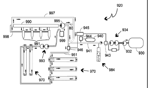
a liquid fuel system, responsive to control signals applied thereto, for
controllably
providing a flow of liquid fuel;
a gaseous fuel system, responsive to control signals applied thereto, for
controllably
providing a flow of gaseous fuel;
a circulation system, receptive of the controlled flow of liquid fuel and the
controlled
flow of gaseous fuel, and disposed in fluid communication with the engine
injection system,
said circulation system providing a liquid-gaseous mixture of the liquid and
gaseous fuels to
the engine injection system and causing the liquid-gaseous mixture to traverse
a circulation
path within which the gaseous fuel is infused into the liquid fuel;
CA 02776165 2012-04-10
- 18c -
said circulation path providing an infusion volume through which the liquid-
gaseous
mixture traverses before being provided to the engine injection system, the
infusion volume
being at least equal to the engine displacement such that substantial
homogeneity of the
liquid-gaseous mixture is provided; and
a control system for generating the control signals to the liquid fuel system
and
gaseous fuel system.
Still according to a further aspect, the invention concerns a homogenizing
fuel
enhancement system for use in conjunction with an internal combustion engine,
the internal
combustion engine having an injection system including an injection pump and
at least one
injector, the system comprising:
a first circulation loop existing outside of, and in fluid communication with,
the
injection system, said first circulation loop continuously circulating and
maintaining the
homogeneity of the multi-fuel mixture, the first circulation loop comprising
at least one
infusion tube defining an infusion volume and causing the liquid-gaseous fuel
mixture to
infuse;
a second circulation loop in fluid communication with the first circulation
loop and
with an injection pump of the engine; and
an accumulator mechanism bridging the first and second circulation loops
taking up
pressure differentials therebetween.
Still according to a further aspect, the invention concerns a homogenizing
fuel
enhancement system for use in conjunction with an internal combustion engine,
the internal
combustion engine having an injection system including an injection pump and
at least one
injector, the system comprising:
a gaseous fuel supply;
at least one circulation path existing outside of, and in fluid communication
with, the
injection system, said circulation path continuously circulating and
maintaining the
homogeneity of the multi-fuel mixture, the first circulation path comprising
at least one
CA 02776165 2013-11-25
- 18d -
infusion tube defining an infusion volume and causing gaseous fuel from the
gaseous fuel
supply to infuse with a liquid fuel to form liquid-gaseous fuel mixture;
a microprocessor control capable of controlling a supply of the gaseous fuel
into the
circulation path;
a flow control valve in-line between a gaseous fuel tank and the circulation
path and
electrically connected to the microprocessor control, the flow control valve
configured to
selectively introduce a gaseous fuel supplied by the gaseous fuel tank into
the liquid fuel; and
a sensor configured to assess gaseous infusion within said circulation path
and
electrically connected to the microprocessor control and configured to assess
gaseous
infusion senses a value corresponding to infusion below a threshold value so
as to prevent
gaseous fuel introduction in excess of predetermined limits.
Still according to a further aspect, the invention concerns an infusion tube
providing homogenizing fuel enhancement for use in conjunction with a
homogenizing fuel
enhancement system of an internal combustion engine having an engine
displacement and
configured to run on a multi-fuel mixture formed onboard, the infusion tube
comprising:
a tube wall capped at each end by a first end wall and an opposite second end
wall,
the first end wall formed with a first passage and a second passage, an
infusion volume
within the infusion tube defined by a space bounded laterally by at least a
portion of the tube
wall and lengthwise by the first and second end walls, the length-to width
ratio of the
infusion volume ranging from approximately five-to-one (5:1) to approximately
twenty-five-
to-one (25:1) and the total infusion volume of the homogenizing fuel
enhancement apparatus
at least equal to the engine displacement; and
a down-tube installed in one of the first or second passages of the first end
wall and
having sufficient length to extend substantially toward the opposite second
end wall,
whereby forcing the multi-fuel mixture flowing through the infusion tube to
travel a
substantial portion of the length of the infusion volume therein promotes
infusion, agitation
and mixing of the liquid-gaseous multi-fuel mixture.
CA 02776165 2013-11-25
- 18e -
The present invention also concerns a method for use in connection with an
internal
combustion engine having a fuel injection system, for increasing the fuel
efficiency of the
internal combustion engine relative to the operation of the engine upon a
liquid fuel applied
to the fuel injection system, comprising the steps of:
creating a controllable flow of the liquid fuel;
controllably feeding a gaseous fuel into the liquid fuel flow to form a flow
of a
liquid-gaseous fuel mixture for ultimate application to the engine fuel
injection system;
causing the liquid-gaseous fuel mixture to flow through a circulation path in
fluid
communication with the engine injection system such that the liquid-gaseous
fuel mixture
traverses a predetermined volume prior to application to the engine fuel
injection system;
generating indicia of the degree of homogeneity of the liquid-gaseous fuel
mixture in
the circulation path; and
controlling the injection of the gaseous fuel into the liquid fuel flow in
accordance
with the indicia of the degree of homogeneity.
[0043] Other features and advantages of aspects of the present invention will
become
apparent from the following more detailed description, taken in conjunction
with the
accompanying drawings, which illustrate, by way of example, the principles of
aspects of the
invention.
CA 02776165 2012-03-29
WO 2011/041705 PCT/US2010/051167
- 19 -
BRIEF DESCRIPTION OF DRAWINGS:
[0044] The accompanying drawings illustrate aspects of the present invention.
In such
drawings:
[0045] Figure 1 is a schematic of an exemplary embodiment of the invention;
[0046] Figure 2 is a schematic of an alternative exemplary embodiment of the
invention;
[0047] Figure 3 is an enlarged side schematic of an exemplary homogenizing
fuel apparatus
according to aspects of the invention;
[0048] Figure 4 is a top schematic thereof;
[0049] Figure 5 is a bottom schematic thereof;
[0050] Figure 6 is a side schematic thereof in use;
[0051] Figure 7 is a schematic of a further alternative exemplary embodiment
of the
invention;
[0052] Figure 8 is a schematic of a further alternative exemplary embodiment
of the
invention;
[0053] Figure 9 is a schematic of a further alternative exemplary embodiment
of the
invention;
[0054] Figure 10 is a schematic of a still further alternative exemplary
embodiment of the
invention;
CA 02776165 2012-03-29
WO 2011/041705 PCT/US2010/051167
- 20 -
[0055] Figure 11 is a schematic of a still further alternative exemplary
embodiment of the
invention;
[0056] Figure 12 is a schematic of a still further alternative exemplary
embodiment of the
invention;
[0057] Figure 13 is an enlarged side schematic of an alternative exemplary
homogenizing fuel
apparatus according to aspects of the invention;
[0058] Figure 14 is a schematic of a still further alternative exemplary
embodiment of the
invention;
[0059] Figure 15 is a schematic of a still further alternative exemplary
embodiment of the
invention;
[0060] Figure 16 is an enlarged side schematic of a further alternative
exemplary
homogenizing fuel apparatus according to aspects of the invention;
[0061] Figure 17 is a flow schematic of three of the homogenizing fuel
apparatuses of Figure
16 installed in series;
[0062] Figure 18 is an enlarged perspective view of an exemplary flow control
apparatus
according to aspects of the invention;
[0063] Figure 19 is a cross-sectional view of the flow control apparatus of
Figure 18 taken
along line 19-19;
[0064] Figure 20 is a schematic of a still further alternative exemplary
embodiment of the
invention;
CA 02776165 2012-03-29
WO 2011/041705 PCT/US2010/051167
- 21 -
[0065] Figure 21 is a schematic of a still further alternative exemplary
embodiment of the
invention; and
[0066] Figure 22 is an enlarged side schematic of an exemplary capillary bleed
device
employed according to aspects of the invention.
MODES FOR CARRYING OUT THE INVENTION:
[0067] The above described drawing figures illustrate aspects of the invention
in at least one
of its exemplary embodiments, which aspects are further defined in detail in
the following
description.
[0068] The subject of this patent application is generally an improved fuel
enhancement
system in various embodiments for use in connection with internal combustion
engines or the
like that builds on the disclosures of the above-referenced applications.
Thus, while the further
exemplary embodiments shown and described herein are focused on specific
aspects of
particularly the fuel enhancement system components relating to the mixing,
circulation, and
delivery of the multi-fuel mixture, here specifically in the context of common
rail or mechanical
injection diesel engines, it will be appreciated by those skilled in the art
that the present
invention is applicable to and may work in conjunction with a variety of
engines, engine fuel
systems, and fuels now known or later developed or discovered and so is not
limited to the
particular embodiments shown and described. Furthermore, it is to be
understood that the word
"fuel" as used throughout the present application and the referenced prior
applications
encompasses any combustible substance or any substance that aids in, enhances
or otherwise
affects combustion in some way. Moreover, a "gaseous fuel" is to be understood
as any such
"fuel" substance that is in a gaseous state at atmospheric conditions, or at
atmospheric pressure
and zero degrees Celsius, such as air or propane, irrespective of the phases
or states such a
gaseous fuel may move through or be in at any particular point in an engine's
fuel delivery
system, injector, or combustion chamber, generally, or in the instant improved
homogenizing
fuel enhancement system, as will be appreciated from the more detailed
explanation of aspects
of the present invention set forth further below.
CA 02776165 2012-03-29
WO 2011/041705 PCT/US2010/051167
- 22 -
[0069] Generally, aspects of the present homogenizing fuel system involve at
least one
circulation loop existing outside of the injection system for continuously
circulating and
maintaining the homogeneity of a multi-fuel mixture apart from any demands by
or delivery to
the engine's injection system (whether mechanical injection or a common rail
or other such
system now known or later developed), and at least one infusion tube
configured within the at
least one circulation loop for providing a volumetric expansion wherein the
fuel mixture is able
to more sufficiently infuse and absorb and thereby become relatively more
homogeneous. Other
variations on these two components are possible without departing from the
spirit and scope of
the present invention. Further aspects of the homogenizing fuel enhancement
system relate to a
control system for controlling, among other things, the on-board metering,
mixing and delivery
of mixed fuel to the engine. Moreover, additional components may be
interchangeably
incorporated in any such homogenizing fuel system for added or ancillary
functionality, such as
an accumulator to account for pressure surges and a fuel cooling means.
[0070] Referring first to Figures 1 and 2, there are shown schematics of
exemplary
embodiments of a homogenizing fuel enhancement system 20 according to aspects
of the
present invention for use in conjunction with a "common rail" diesel engine,
the respective
embodiments differing primarily in the fuel system control means ¨ electrical
versus mechanical
¨ more about which will be said below. As a threshold matter, it is noted that
while a number of
engine components are shown as part of the figures generally throughout, such
as the common
rail or fuel gallery, the injectors, the fuel filter, the diesel tank and lift
pump, and related fuel
lines and the like, all such components or any variations thereof or
substitutions therefor may be
employed, whether factory-installed or after-market, in conjunction with the
present invention
without departing from its spirit and scope. Thus, while such components are
shown in the
various figures as part of the overall fuel system, it is to be understood
that the invention is
expressly not limited thereto and that no claim is made to such standard
components of an
engine, which are provided herein simply as context for the homogenizing fuel
enhancement
system of the present invention. Moreover, again, while the exemplary
embodiments are
specifically shown and described in connection with a diesel internal
combustion engine, a
variety of other engines now known or later developed may be employed,
including but not
limited to gasoline direct injection engines.
CA 02776165 2012-03-29
WO 2011/041705 PCT/US2010/051167
- 23 -
[0071] In the first exemplary embodiment of Figure 1, there is shown an
overall fuel system
20 generally including a diesel tank 30 with a lift pump 32 and a pressurized
propane tank 40
both feeding into a circulation loop generally designated 50 and including an
infusion tube 70,
one or more of which defining a homogenizing fuel enhancement apparatus, the
circulation loop
50 being in fluid communication with the engine's injection system common rail
90 and
injectors 91, here by way of the fuel filter 99. In more detail, the diesel
tank 30 supplies diesel
fuel through a fuel line 31 by way of the lift pump 32 at about 5 psi, all of
which are factory-
installed equipment that could be self-contained within the tank 30 or
separately configured as
shown for convenience in Figure 1. The diesel fuel then passes via fuel line
33 to a further
circulation loop delivery pump 34 that takes the diesel fuel up to
approximately 15-20 psi in the
exemplary embodiment. It will be appreciated that the circulation loop
delivery pump 34 may
be any fluid pump now known or later developed and configured for appropriate
pressures and
power draw and to accommodate diesel and other such light oil fuels, including
but not limited
to turbine-style, gear, rotary vane, or roller vane pumps as manufactured by
Robert Bosch LLC
in Farmington Hills, Michigan, or proprietary positive displacement pumps
configured to
accommodate liquid-gaseous fuel mixtures as manufactured or licensed by US
Airflow in Vista,
California, which pump technology is the subject of U.S. Patent No. 7,721,641
issued on May
25, 2010, and numerous co-pending patent applications, including but not
limited to PCT App.
No. US2005/018142, filed May 23, 2005, and PCT App. No. US2008/012533, filed
November
6, 2008, and any national stage cases derived therefrom. In alternative
embodiments, one or
more such delivery pumps may be multi-stage or may be ganged or placed in
series to achieve
the necessary throughput and pressurization. Any or all such delivery pumps as
well as other
circulation pumps, high pressure positive displacement pumps or the like that
are employed
within the system may be powered and controlled using any appropriate means
now known or
later developed, including but not limited to a pulse-width modulator (not
shown). Back to the
fuel enhancement system 20, in the first exemplary embodiment, there is
provided a flow sensor
43 in-line between the diesel tank 30 and the circulation loop 50, there being
a fuel line 35
connecting the circulation loop delivery pump 34 and the flow sensor 43 and a
further fuel line
41 from the flow sensor 43 to the fuel line 51 of the circulation loop 50.
Additionally, the
propane tank 40 supplies propane through fuel line 37 to a flow control valve
44 that then
supplies propane through fuel line 38 to the fuel line 41 carrying the diesel
fuel as metered by
CA 02776165 2012-03-29
WO 2011/041705 PCT/US2010/051167
- 24 -
the flow sensor 43. Preferably the propane tank 40 is regulated to a minimum
pressure of at
least approximately 10 psi greater than the pressure in the fuel line 41 into
which the propane is
feeding, in the exemplary embodiment, once more, on the order of 15-20 psi,
such that the
propane is in-fed at approximately 25-30 psi. The flow control valve 44 is
controlled by a
microprocessor control 45 or the like, which control 45 may be any such device
now known or
later developed for electrically controlling valves or other such flow control
devices and may
act on data received from a variety of inputs including but not limited to the
flow sensor 43 of
the exemplary embodiment, a throttle sensor, or another such monitoring device
in a manner
known in the art. Accordingly, those skilled in the art will appreciate that
while an exemplary
electronic metering control is shown and described in connection with the
first exemplary fuel
enhancement system 20 of Figure 1, the invention is not so limited, but may
instead involve any
such components in a variety of combinations and configurations without
departing from its
spirit and scope. In the exemplary embodiment, the ratio of fuels within the
fuel mixture is
more than ninety percent (90%) diesel and less than ten percent (10%) propane
by volume at the
point of mixing, assuming the mixing pressure is at a nominal 80 psi.
Generally, the higher the
mix pressure the higher the ratio of gaseous fuel and the higher the
efficiency gain, to a point,
such that it will be appreciated that higher pressures within the system at or
after the point of
mixing may be employed without departing from the spirit and scope of the
invention. It will be
further appreciated by those skilled in the art that while two particular fuel
constituents are
described as comprising the fuel mixture, namely liquid diesel fuel and
gaseous propane, and
within a specific proportion range, the invention is not so limited and a
variety of other fuels as
that term is used herein may be employed in various combinations and
proportions in
conjunction with a homogenizing fuel enhancement system according to aspects
of the present
invention without departing from its spirit and scope, as further evidenced by
the alternative
exemplary embodiments of Figures 9-12 discussed below. In whatever proportion
the fuel
constituents are mixed, it will be appreciated that with that ratio set and
dictated by the
microprocessor control 45 based on data it receives from the flow sensor 43 in
the diesel fuel
line and the resulting control it has of the propane delivered to the diesel
fuel through the flow
control valve 44, there is thus little to no variation in the actual
proportion or ratio of the
constituents within the fuel mixture, which remains substantially constant in
operation. And
though the flow control valve could be "always on" and the flow therethrough
of propane
CA 02776165 2012-03-29
WO 2011/041705 PCT/US2010/051167
- 25 -
increased or decreased to remain at the desired proportion relative to the
diesel fuel flowing
through fuel line 41 as measured and reported by the flow sensor 43, in the
preferred
embodiment the flow control valve 44 is simply switched "on" and "off" by the
microprocessor
control 45, with the frequency and duration of the "on" propane "pulses" being
again dictated
by the flow rate of the diesel fuel so that the resulting fuel mixture is of a
substantially constant
ratio of diesel to propane and only the total volume of such mixture is turned
up and down by
the system in response to the demands of the engine; i.e., the demand for
diesel fuel as dictated
by throttle position controlling the injector pump 95 downstream and thereby
having an
upstream effect on the flow rate of diesel fuel from the tank 30 as measured
by the flow sensor
43. It will be appreciated that, as such, the fundamental operation of the
engine's fuel delivery
system is unaffected by the addition of the homogenizing fuel enhancement
system 20 of the
present invention, which operates essentially outside and independent of the
factory equipment.
While a particular group of electronic control devices operably connected in a
particular
configuration as shown and described in connection with Figure 1 and metering
and delivering
to the circulation loop 50 of the fuel enhancement system 20 a substantially
fixed-ratio liquid-
gaseous fuel mixture, those skilled in the art will appreciate that a number
of other such control
devices may be employed in various combinations to effectively meter and
control the mixing
of two or more fuel components without departing from the spirit and scope of
the present
invention.
[0072] With continued reference to Figure 1, the exemplary diesel-propane fuel
mixture is
passed through fuel line 41 to the circulation loop 50, specifically, where
the fuel line 41 tees
into a fuel line 51 returning excess fuel from the injection pump 95 for
recirculation. Fuel line
51 is in fluid communication with the inlet leg 61 of an optional heat
exchanger 60 having one
or more switchback legs 62 before passing through an outlet leg 63 of the heat
exchanger 60 and
into a further fuel line 52 of the circulation loop 50. In the exemplary
embodiment wherein the
circulation loop 50 includes such a heat exchanger 60, it will be appreciated
that the additional
flow passages and the resulting increased surface area has a cooling effect on
the fuel mixture as
it passes therethrough. In the present invention, this is desirable not only
in that generally to
maintain lower fuel temperatures relative to the vehicle's under hood
temperature is known to
contribute to a more stable and more complete downstream combustion (i.e.,
reducing inlet fuel
CA 02776165 2012-03-29
WO 2011/041705 PCT/US2010/051167
- 26 -
temperature has a correlated effect on reduced combustion temperature) and
thus to reduced
emissions and engine wear. Reduced fuel temperature within the circulation
loop 50 is further
desirable in the specific context of the present invention as it relates to
the infusion tube 70
immediately downstream of the heat exchanger 60 in the exemplary embodiments
of Figures 1
and 2, in which the fuel mixture is slowed and, based on the fluid flow
dynamics within the
volumetric expansion of the infusion tube 70, more about which is said below
in connection
with Figure 6, the fuel mixture, and particularly the gaseous component
thereof, here the
propane, further cools and infuses within the liquid fuel component, here the
diesel, thereby
resulting in a substantially homogeneous fuel mixture passing through the
remainder of the
circulation loop 50 and made available to the engine's common rail 90.
Furthermore, cooling
such a diesel-propane fuel mixture as employed in the exemplary embodiment
effectively
reduces vapor formation within the system, thereby helping prevent vapor lock.
Thus, it will be
appreciated that generally a heat exchange device of some kind installed
within the circulation
loop 50 to cool the fuel mixture as it circulates has advantages in use,
particularly in the context
of the novel infusion tube 70 also included in the circulation loop 50 of the
present invention.
As such, it will be further appreciated that while a radiator-style heat
exchanger 60 is shown and
described in connection with the exemplary embodiments of Figures 1 and 2, the
invention is
not so limited, but instead may include any heat exchange device now known or
later
developed, if any, without departing from the spirit and scope of the
invention, including but not
limited to optional heat exchange fins 89 (Figs. 3-6) formed on the infusion
tube 70 instead of or
in addition to any other heat exchange or cooling devices within the fuel
enhancement system
20. As mentioned briefly above, immediately downstream of the heat exchanger
60 is the
infusion tube 70, with fuel line 52 as part of the overall circulation loop 50
interconnecting the
outlet leg 63 of the heat exchanger with the inlet tube 75 (Figs. 3-6) of the
infusion tube 70.
The fuel mixture then passes through the infusion tube 70 and out the outlet
down-tube 76 (Figs.
3-6) as described separately in much greater detail below. In sum, it is in
the infusion tube 70,
which is a specifically configured volumetric expansion within the circulation
loop 50, that the
liquid-gaseous fuel mixture becomes substantially homogeneous as the gaseous
fuel component
is effectively infused within or dispersed throughout the liquid fuel
component as caused at least
in part by the geometry of the infusion tube 50 and the resulting fluid
dynamic effects on the
fuel mixture. The substantially homogeneous and relatively cool fuel mixture
exiting the
CA 02776165 2012-03-29
WO 2011/041705 PCT/US2010/051167
- 27 -
infusion tube 50 through the outlet tube 76 (Figs. 3-6) then passes through
fuel line 53 to the
fuel filter 99. From the fuel filter 99, the fuel mixture next passes through
the only outlet fuel
line 92 to a circulation pump 93 that takes the fuel mixture up to a nominal
pressure of
approximately 60 psi before it passes along fuel line 94 to the engine's
injection pump 95 that in
the exemplary common rail diesel engine configuration takes the fuel mixture
up to a working
pressure on the order of 25,000 psi. The fuel mixture needed by the engine is
delivered from the
injection pump 95 along fuel line 96 to the common rail 90, while unneeded
fuel, or fuel beyond
the engine's present demand, recycles through the circulation loop along fuel
line 51 also in
fluid communication with the injection pump 95, and so the cycle continues
back through the
heat exchanger 60 and infusion tube 70 as above-described, with additional
fuel mixture
entering the circulation loop 50 as needed and joining the recycled fuel just
before the heat
exchanger 60. It will be appreciated by those skilled in the art that the
circulation pump 93 and
the injection pump 95 may be of any type now known or later developed for the
purpose of
delivering and pressurizing the fuel mixture, here, the two being factory-
installed equipment.
As factory-installed and configured, both the circulation pump 93 and the
injection pump 95 run
continuously when the engine is running. It is then important to note for
these purposes that the
homogenizing fuel enhancement system 20 of the present invention and the
operation of the
infusion tube 70 as described above and further below in more detail serves to
effectively mix
and infuse the gaseous fuel component within the liquid fuel component, such
that the resulting
circulated, substantially homogeneous mixture is effectively seen by the rest
of the system, and
the delivery and injection pumps, specifically, as a liquid. It will be
further appreciated that the
circulation loop 50 as thus shown and described herein is a dynamic system
that continuously
mixes and circulates the fuel mixture, whereby there is no static operation,
holding tanks, dead
spaces, or the like as in prior art circulation systems. In addition, by
effectively existing and
operating outside of the engine's injection system, the circulation loop 50 is
once again capable
of not only continuous and dynamic circulation, but thereby also maintaining
the substantially
homogeneous fixed ratio of liquid and gaseous fuel components in a low-
pressure management
context versus the high-pressure context of the common rail 90. As is standard
on many
common rail diesel engines and other such engines, unused or blow-by fuel from
both the
common rail 90 and the individual injectors 91 is fed back into the fuel
filter 99 along spill-port
fuel lines 97 and 98, respectively, for further recirculation and use.
Similarly, a further novel
CA 02776165 2012-03-29
WO 2011/041705 PCT/US2010/051167
- 28 -
feature of the present invention as it relates to the infusion tube 70 is the
inclusion therein of an
accumulator mechanism 84 (Fig. 3), which includes a blow-by outlet 82 (Fig. 3)
in its base for
passing fuel that has seeped by the accumulator mechanism 84 out of the
infusion tube 70 and
through a blow-by return line 68, in the exemplary embodiment, teeing back
into the fuel line 33
between the lift pump 32 and the circulation loop delivery pump 34 for further
processing.
Finally, the exemplary embodiment of Figure 1 also includes a bypass fuel line
65 teeing from
the fuel line 35 between the circulation loop delivery pump 34 and the flow
meter 43 and
connecting directly to the filter 99, thereby bypassing the flow meter 43 and
fuel additive source
40 and the entire circulation loop 50 and thus enabling the provision of pure
diesel directly to
the engine's common rail 90 if there were to be a problem in another portion
of the fuel
enhancement system 20. Controlling the operative flow of diesel through the
bypass fuel line
65 is an in-line pressure switch or check valve 66 that only opens if the
pressure on the
downstream side of the valve 66 (i.e., the pressure in the fuel filter 99 or
the fuel line 92 running
to the circulation pump 93, injection pump 95, and ultimately the common rail
90, drops to a
point below the pressure in the bypass fuel line as dictated by the
circulation loop delivery
pump 34, here on the order of 15-20 psi, which would indicate that the engine
is not getting
sufficient fuel for some reason. Those skilled in the art will appreciate that
in this way the
homogenizing fuel enhancement system 20 of the present invention has a fail-
safe mode of
operation wherein if there is any downstream failure of any component within
the circulation
loop 50, there is a clog somewhere in the related lines, or there is simply no
more fuel additive
(i.e., the propane tank 40 is empty or low on pressure), the system 20 will
simply revert to
running on only diesel fuel, such that the engine or vehicle will continue in
an uninterrupted or
seamless operation as it transitions back to its original "diesel only" fuel
system, with the only
downside being the factory fuel mileage rather than the enhanced mileage
achieved through
implementation of the present invention. This effect is again appreciated in
view of the fact that
the fuel enhancement system 20 of the present invention operates essentially
outside and
independent of the factory fuel system equipment, which easily and
conveniently lends itself to
such a "fail-safe" fuel bypass. It will be further appreciated that while a
particular arrangement
of the fuel system components and their connectivity through a number of fuel
line segments is
shown and described in connection with the exemplary embodiment of Figure 1,
the present
invention is not so limited. Rather, such components and the means by which
they are
CA 02776165 2012-03-29
WO 2011/041705 PCT/US2010/051167
- 29 -
connected and rendered inter-operable may take a variety of configurations
without departing
from the spirit and scope of the invention. Again, since Figure 1 is a
schematic view of one fuel
system embodiment according to aspects of the present invention, the relative
sizes and shapes
of the various components are not to be taken strictly, but instead are to be
understood as being
merely illustrative of the principles and features of the homogenizing fuel
enhancement system
of the present invention. Accordingly, the substitution of various alternative
components
serving substantially the same function as those shown and described is
possible in the present
invention and is expressly to come within its scope.
[0073] Turning briefly to Figure 2, there is shown an alternative embodiment
of the fuel
system 20 of the present invention much like that of Figure 1 configured for
use in conjunction
with a common rail diesel engine, where here there is a mechanical rather than
electronic
control of the metering and delivery of the fuel components to the circulation
loop 50.
Specifically, rather than a microprocessor control 45 operably connected to a
flow sensor 43 in
the diesel fuel line and a flow control valve 44 in the propane fuel line
(Fig. 1), instead a
metering pump 36 is employed in mechanically metering the fuel components for
subsequent
mixing. Here, the circulation loop delivery pump 34 passes the diesel fuel
from the tank 30 to
the metering pump 36 by way of fuel line 35. Separately, the propane gaseous
fuel as supplied
by pressurized tank 40 passes to the metering pump 36 via fuel line 37 at an
approximate
regulated pressure to be fixed within the range of 30-80 psi. The metering
pump serves to
mechanically meter and mix the diesel and propane using any such pump
technology now
known or later developed, potentially involving multiple discrete pumps or
piston units that are
slaved to a common drive so as to again effectively mechanically meter the
respective fuel
constituents passing therethrough. That is, in this alternative exemplary
embodiment, the
geometry and mechanical operation of the metering pump 36 will set or fix the
volumetric ratio
of the diesel relative to the propane in a manner generally known in the art,
with the metering
pump 36 then being turned up or down or simply "on" or "off" based on the
demands of the
engine, as described more fully below, again, without any variation in the
actual proportion or
ratio of the constituents within the fuel mixture, which remains substantially
constant. Those
skilled in the art will appreciate that the operation of the metering pump 36
as it relates to the
total volume of fuel mixture delivered to the circulation loop 50 may be tied
to one of a number
CA 02776165 2012-03-29
WO 2011/041705 PCT/US2010/051167
- 30 -
of control or measurement devices now known or later developed, such as a
downstream
mechanical pressure switch, a flow meter, a throttle sensor, or a
microprocessor electronic
control (the latter example effectively being a combined electro-mechanical
control system). In
the case of a mechanical switch, it will be appreciated that such could be
operable within the
metering pump 36 itself, within the infusion tube 70 as triggered by the
position of the
accumulator piston 85, as by one or more pressure, position or proximity
switches, more about
which will be said below in connection with Figure 3, or simply within a fuel
line downstream
of the metering pump 36 as shown. Specifically, in the exemplary embodiment, a
first fuel line
38 coming out of the metering pump 36 is for metered delivery of the diesel
fuel, while a
separate second fuel line 39 also coming out of the metering pump 36 carries
the propane or
other gaseous fuel component, also mechanically metered and not yet mixed with
the diesel. In
this embodiment, preferably a pressure switch 42 is then placed at some
location within the first
fuel line 38 carrying the liquid diesel fuel before the mixing point where the
first fuel line 38
joins the second fuel line 39, which will enable more accurate and consistent
feedback of the
actual fuel system demands than by monitoring pressure in the gaseous fuel
line or in a
downstream fuel line in which a liquid-gaseous fuel mixture is being
circulated. Once again,
those skilled in the art will appreciate that while a number of variations for
mechanical
metering, sensing, and control of the fuel mixture and delivery processes have
been shown and
described, the invention is not so limited but may instead involve a variety
of other such
components now known or later developed in providing the operable effects. In
any case, the
exemplary diesel-propane fuel mixture is passed from the metering pump 36 and
the first and
second fuel lines 38, 39 through single fuel line 41 to the circulation loop
50 for further
processing as described above in connection with Figure 1. A heat exchanger 60
is again shown
in-line within the circulation loop 50 between the inlet point for additional
fuel mixture as
supplied by fuel line 41 and the downstream infusion tube 70, though once more
it will be
appreciated that other such cooling devices alone or in combination may be
employed in the
homogenizing fuel enhancement system 20 of the present invention.
[0074] Referring now to Figures 3-6, there are shown various enlarged
schematic views of the
infusion tube 70 of Figures 1 and 2 so as to better illustrate its structure
and function. It will be
appreciated that, as schematics, Figures 3-6 are not necessarily drawn to
scale and so are not to
CA 02776165 2012-03-29
WO 2011/041705 PCT/US2010/051167
- 31 -
be taken as exact representations particularly as to how the infusion tube
would be dimensioned
or proportioned (e.g., length, width, wall thicknesses, etc.). Rather, these
schematics, again, are
representative of the overall structure and principles of operation of the
novel infusion tube 70
that is part of the fuel enhancement system 20 of the present invention, and
particularly the
circulation loop 50.
[0075] First, in Figure 3 there is shown an enlarged schematic cross-sectional
view of the
infusion tube 70. It can be seen that in the exemplary embodiment the infusion
tube 70
generally comprises an annular tube wall 71 capped at each end by an annular
upper wall 72 and
an annular lower wall 80, each sealed within the tube wall 71 by at least one
seated o-ring 83 in
a manner known in the art. One or both of the upper and lower walls 72, 80 may
be integral
with the tube wall 71 or may be permanently or removably installed within the
tube wall 71 so
as to form the infusion tube 70 using any assembly technique now known or
later developed,
including but not limited to press or interference fit, threaded engagement,
bonding, welding,
retaining rings or other mechanical couplings or retainers, etc. In the
exemplary embodiment,
retaining rings 79 are configured to engage respective grooves (not shown)
formed in the tube
wall 71 so as to trap each end wall 72, 80 against a stepped shoulder formed
in each end of the
tube wall 71, thus temporarily securing the end walls 72, 80 in a secure and
sealed manner while
still allowing for relatively easy removal of one or both walls 72, 80 for
repair or inspection of
the inner components of the infusion tube 70. For example, an accumulator
mechanism
generally designated 84 is in the exemplary embodiment installed in the lower
end of the
infusion tube 70 adjacent the lower wall 80, the accumulator mechanism 84
comprising a piston
85 slidably installed within the infusion tube 70 and biased upwardly, or
toward the upper wall
72, by a spring 86 installed between the piston 85 and the lower wall 80. A
resilient seal or
piston ring 87 is seated within the piston 85 to slidingly and sealingly
engage the tube wall 71.
The piston ring 87 can take any appropriate shape and be formed of any
suitable materials now
known or later developed, including but not limited to a Buna-N o-ring, lip
seal, or u-cup piston
seal. As such, the accumulator mechanism 84, and the piston 85 particularly,
defines an upper
space or infusion volume 88 within the infusion tube 70 above the piston 85
between the piston
85 and the upper wall 72, bounded laterally by a portion of the tube wall 71.
It will be
appreciated that the infusion volume 88 will fluctuate depending on the
pressure in the
CA 02776165 2012-03-29
WO 2011/041705 PCT/US2010/051167
- 32 -
circulation loop 50 generally and in the infusion tube 70 specifically, with
the spring 86 taking
up those variances and serving to apply through the accumulator piston 85 the
appropriate
pressure on whatever fuel mixture is in the upper volume 88 at any given time,
more about
which will be said below particularly in connection with Figure 6. It will be
appreciated that a
separate commercially available bladder-style accumulator, for example, may be
substituted for
the accumulator mechanism 84 without departing from the spirit and scope of
the present
invention. In the exemplary piston-style accumulator 84, in connection with
measurement of
pressure or other such system data for the purpose of feedback and control of
the metering and
delivery process for the fuel mixture, and by way of further example, a
magnetic material may
be employed within at least a portion of the piston 85 and at least one
corresponding position or
proximity switch as is known in the art may be configured within the tube wall
71 of the
infusion tube 70, such that relative vertical movement of the piston 85 within
the infusion tube
70 as an indicator of circulation loop pressure and hence fuel demand by the
engine can be
ascertained and communicated to a control device such as a microprocessor 45
(Fig. 1) or
metering pump 36 (Fig. 2). With continued reference to Figure 3, in the
exemplary
embodiment, two holes or first and second upper passages 73, 74 are formed in
the upper wall
72 to serve as inlet and outlet, respectively, of the infusion tube 70 for the
fuel traveling through
the circulation loop 50, though it will be appreciated that in alternative
embodiments there may
be more than two total passages and one or more of the inlets or outlets may
be positioned in the
tube wall 71 rather than the upper wall 72, for example, as shown
schematically in Figures 1, 2
and 7-10, such that the exemplary structure is to be appreciated as being
merely illustrative. As
a further aspect of the inlet and outlet of the infusion tube 70 in the
exemplary embodiment, a
relatively shorter inlet tube 75 is shown as being installed within the first
upper passage 73 and
a relatively longer outlet down-tube 76 is shown as being installed within the
second upper
passage 74, once again, more about which will be said below. In sum, though,
the fluid flow
path into and out of the infusion volume 88 of the infusion tube 70 then
involves in the
exemplary embodiment flow through the inlet tube 75 and down through the
infusion volume 88
against the slight pressure resistance of the accumulator mechanism 84 until
reaching the outlet
tube bottom or interior end 78 so as to travel up the outlet tube 76 and back
into the circulation
loop 50. As will be more fully appreciated from the below discussion in
connection with Figure
6, this flow path as dictated, in part, by the longer outlet tube 76 relative
to the inlet tube 75, and
CA 02776165 2012-03-29
WO 2011/041705 PCT/US2010/051167
- 33 -
hence the spatial position of the inlet tube bottom end 77 above the outlet
tube bottom end 78,
creates a dynamic flow effect within the volumetric expansion or infusion
volume 88 of the
infusion tube 70 that causes an infusion or substantially homogeneous mixing
of the liquid-gas
fuel mixture without necessarily requiring circulation loop pressures
sufficient in and of
themselves to liquefy any gaseous fuel component in the fuel mixture, which it
will be
appreciated has tremendous advantages in practice. In an exemplary embodiment,
the infusion
tube 70 is configured with a tube wall 71 made of steel or extruded aluminum
tubing having a
nominal outside diameter of two inches (2") and nominal inside diameter of one
and seven
eighths inch (1-7/8") and an overall length of approximately twenty-one inches
(21").
Alternatively, the tube wall 71 may also be formed of an outer aluminum
extrusion with an
inner steel sleeve for wear resistance or other reasons, in such an embodiment
the inner sleeve
may be shorter than the outer aluminum extrusion by the appropriate amount
such that the
sleeve itself forms the upper and lower shoulders against which the upper and
lower walls 72,
80 may seat. The upper and lower walls 72, 80 are formed of an aluminum or
steel disk having
an outside diameter slightly larger than the inside diameter of the tube wall
71 so as to seat on
the upper and lower shoulders as described. The thickness of the upper wall 72
is roughly two
and half inches (2-1/2") and the thickness of the lower wall 80 is roughly one
and half inch (1-
1/2"). The piston 85 of the accumulator mechanism 84 is also a steel or
aluminum disk having
an outside diameter roughly equivalent to the inside diameter of the tube wall
71 and a thickness
of roughly one and half inch (1-1/2"). The spring 86 is a nominal one inch
(1") coil spring
having an at rest length of roughly four inches (4"). The spring 86 may be
held in place
substantially centered on the piston 85 and/or lower wall 80 by a center stud
(not shown). The
piston ring 87 positioned on the piston 85 is a nominal three eighths (3/8")
thick u-cup piston
seal made of Buna-N. Based on the foregoing illustrative dimensions, it will
be appreciated that
the nominal or at-rest length of the space defining the infusion volume 88
within the infusion
tube 70 is about eleven and half inches (11-1/2"). Extending into this volume
lengthwise is the
outlet tube 76 having a nominal length from the base of the upper wall 72 of
about eleven inches
(11"), such that there is approximately a half inch (1/2") clearance between
the lower end 78 of
the outlet tube 76 and the accumulator piston 85. The outlet down-tube 72 is a
nominal half
inch (1/2") outside diameter (0.D.) and seven sixteenths inch (7/16") inside
diameter (I.D.) steel
tube. It follows that the approximate nominal or at-rest infusion volume 88 of
the exemplary
CA 02776165 2012-03-29
WO 2011/041705 PCT/US2010/051167
- 34 -
infusion tube 70 is thirty two cubic inches (32 in3) (Volume = Length x Area =
11.5 in. x (H x
(.94 in.)2)) (not accounting for the movement of the piston 85 or the
relatively negligible volume
taken up by the outlet tube 76 itself (i.e., its wall) of roughly two cubic
inches (2 in3)).
Comparing the flow volume within the outlet tube 76 to that of the rest of the
infusion tube 70
surrounding the outlet tube 76, it will be appreciated that as those two
volumes are more
equivalent, a substantially equal rate or velocity of flow into and out of the
infusion tube 70 may
be established, while as the volume of the outlet down-tube 76 becomes smaller
relative to the
whole, the fuel mixture will have a tendency to speed up as it exits, more
about which is said
below in connection with particularly the alternative "reverse flow" infusion
tube 770 of Figure
16. Referring still to Figure 3 and the construction and operation of the
first exemplary infusion
tube 70, feeding into the infusion volume 88 is the fuel mixture through a
nominal half inch
(1/2") I.D. high-pressure hose. The fuel mixture exiting the fuel line 52
(Figs. 1 and 2) into the
infusion tube 70, and the infusion volume 88, specifically, via the inlet tube
75 thus goes
through an expansion from a roughly half inch (1/2") I.D. fuel line to a
roughly two inch (2")
I.D. infusion tube 70. This expansion and the subsequent length over which the
fuel mixture
then travels downwardly through the infusion volume 88 before exiting through
the outlet tube
76 has the effect of slowing and infusing the fuel mixture, as explained in
even more detail
below in connection with Figure 6, though without over-restricting the flow so
as to cause a
system back-pressure and additional work on, and resulting losses from, the
circulation pump;
rather, maintaining a sufficient circulation loop flow rate through the
system, including the one
or more infusion tubes 70, can both reduce overall power draw and also help
avoid gas pocket
formation. Those skilled in the art will appreciate that the aspects and
principles of the fuel
enhancement system 20 of the present invention as it relates to the infusion
tube 70 particularly
are not in any way limited to the specific exemplary geometry and construction
shown and
described, which is to be understood as being merely illustrative, but instead
may take a number
of other configurations without departing from the spirit and scope of the
invention, which will
be further appreciated from the below discussion related to alternative
infusion tube
configurations in connection with Figures 11 and following. Relatedly, as
another way of
expressing the geometry of the exemplary infusion tube 70, it will be
appreciated that the
length-to-diameter ratio of the infusion volume 88 is on the order of five to
one (5:1)
(approximately a ten inch length versus approximately a two inch diameter).
While again a
CA 02776165 2012-03-29
WO 2011/041705 PCT/US2010/051167
- 35 -
variety of other configurations can be employed in the present invention,
preferably the length-
to-diameter ratio will remain in this five to one (5:1) order of magnitude
range to get the desired
effects, with the infusion tube 70 then being simply scaled up or down
depending on the
application (total fuel mixture through-put expected). In any case, the length-
to-diameter ratio
"order of magnitude range" in the exemplary embodiment would be from about two
to one (2:1)
up to about thirty to one (30:1), with again on the order of five to one (5:1)
being preferable in
the exemplary fuel enhancement system 20.
[0076] Briefly turning to Figures 4 and 5, there are shown schematic top and
bottom views,
respectively, of the infusion tube 70. In Figure 4, viewing the infusion tube
70 from the top it
can be seen that the inlet tube 75 is in the exemplary embodiment
substantially centered in the
upper wall 72 with the outlet down-tube 76 then being substantially parallel
to and offset from
the inlet tube 75. The fluid flow effects of this particular positioning of
the inlet and outlet
tubes 75, 76 will once again be best understood with reference to Figure 6,
discussed further
below. The bottom view of Figure 5 taken in conjunction with Figure 3 shows a
blow-by outlet
82 installed in a radially offset location in the bottom wall 80 of the
infusion tube 70, though it
will be appreciated that the exact location of the blow-by outlet 82 is in
many ways arbitrary, so
long as it does not interfere with the operation of the biasing spring 86 of
the accumulator
mechanism 84. It will be further appreciated as explained above in connection
with Figure 1
that the purpose of the blow-by outlet 82 is to allow any fuel mixture that
has seeped by the
piston 85, and the piston ring 87 specifically, to be collected and returned
to the circulation loop
50, in the exemplary embodiment of Figures 1 and 2 by way of return line 68
and the inlet side
of the circulation loop delivery pump 34. In connection with the fuel mixture
passing by the
piston 85 of the accumulator mechanism 84, those skilled in the art will also
appreciate that
such a fuel mixture including a light oil fuel like diesel will have a
lubricating effect for the
moving parts of the infusion tube 70, namely the piston 85 as it travels up
and down within the
tube 70 as bounded by the tube wall 71.
[0077] Referring now to Figure 6, there is shown a schematic cross-sectional
view of the
infusion tube 70 illustrating the flow and fluid dynamics of the fuel mixture
as it moves through
the infusion tube 70 as part of the circulation loop 50 (Figs. 1 and 2). As
the fuel mixture
CA 02776165 2012-03-29
WO 2011/041705 PCT/US2010/051167
- 36 -
generally designated 22 enters the infusion volume 88 of the infusion tube 70
through the inlet
tube 75, the mixture 22 is in the exemplary embodiment a liquid-gaseous
mixture, namely diesel
plus propane, at a nominal pressure on the order of 20 psi, thus well below
the pressure at which
propane undergoes a phase transformation from gas to liquid at atmospheric
temperature
-- (approximately 125 psi). As such, the liquid-gaseous fuel mixture continues
to have at least one
constituent in the gaseous phase when mixed and circulated and when introduced
into the
infusion tube 70, specifically. Therefore, as shown schematically in Figure 6,
as the fuel
mixture 22 enters the inlet tube 75, it includes relatively large bubbles 23
representative of the
gaseous propane. But as the fuel mixture 22 flows downward within the infusion
volume 88 as
-- indicated by arrows 28 in Figure 6 an eddy current effect is caused as the
incoming liquid
disperses within the liquid already present within the infusion volume 88. In
addition, such
descending liquid fluid flow resists the tendency of the bubbles 23 to rise,
which action causes
the bubbles 23 to break apart until by the time the mixture 22 reaches the
bottom of the infusion
volume 88 and begins to make its way up the outlet down-tube 76 and out of the
infusion tube
-- 70, the bubbles as generally designated 24 are now relatively small as
being representative of
the propane that has been sufficiently dispersed within the diesel fuel to
form a substantially
homogeneous liquid-gaseous fuel mixture 22 upon exiting the infusion tube 70
as indicated by
arrows 29. In a bit more detail, the bubbles 23 representative of the propane
or other gaseous
fuel within the fuel mixture break apart upon entry into the infusion tube 70
effectively due to
-- the shear forces in the liquid that overcome the surface tension of the
bubbles, causing the
bubbles to break apart and consequently a reduction in bubble size. The eddy
currents in the
infusion tube 70 cause the fluid to work against itself, creating a turbulent
mixing action. This
action is deliberately intensified in the present design by the introduction
of the fuel mixture
into the top of the infusion tube 70, which provides an environment where the
bubbles attempt
-- to rise against the downward flow of the liquid-gas fuel stream. The result
is a relatively
controlled, repeatable process to divide and decrease the bubble size to the
desired level and
thoroughly mix the gaseous bubbles into the fuel stream, or disperse them
within the liquid
component of the fuel mixture, to provide the desirable result of massive
atomization upon
injection of the liquid fuel from within the fuel itself, instead of trying to
influence the fuel from
-- the outside as has been attempted in prior art designs. It will be
appreciated by those skilled in
the art that the infusion tube 70 thus has a number of beneficial physical
effects on the fuel
CA 02776165 2012-03-29
WO 2011/041705 PCT/US2010/051167
- 37 -
mixture 22 as it passes therethrough, all essentially dictated by the geometry
and configuration
of the infusion tube 70. Again, as the fuel mixture 22 exits the inlet tube 75
into the infusion
volume 88 it undergoes a volumetric expansion that serves to slow down and
cool the fuel
mixture 22. This alone encourages the infusion process and, specifically, the
tendency of the
gaseous fuel component to contract. As described above, the downwardly flowing
fuel mixture
22 also resists the tendency of the gas bubbles to rise, both by inertial and
frictional effects.
Once more, this confluence of descending fuel mixture and ascending bubbles
tends to cause a
replicating, cascading effect that further mixes or agitates the fuel mixture
in a controlled
turbulent mixing process, thereby minimizing any unnecessary heat or parasitic
energy losses
while creating a substantially homogeneous liquid-gas fuel mixture. Thus,
those skilled in the
art will appreciate that the physical, spatial arrangement of the bottom end
77 of the inlet tube
75 above the bottom end 78 of the outlet down-tube 76 in the exemplary
embodiment causes the
above-described flow path and the resulting mixing effects. It will be
appreciated that while the
infusion tube 70 is illustrated as being substantially vertical, other
orientations alone or in
combination with other geometries of the infusion tube 70 and its components,
particularly the
inlet and outlet tubes 75, 76, are possible so as to maintain the relative
positions of the bottom
ends 77, 78 and still obtain the resulting fluid flow dynamics explained
above. It will be further
appreciated by those skilled in the art that the accumulator mechanism 84
cooperates with the
other features of the infusion tube 70 to maintain consistent pressure in the
fuel mixture 22 as it
moves through the infusion volume 88, the accumulator also serving to take up
pressure surges
and the like felt throughout the circulation loop 50 in a manner known in the
art. Thus, by
locating the accumulator mechanism 84 within the infusion tube 70 its benefits
for the
circulation loop 50 and overall fuel enhancement system 20 are still realized
while additional
functionality in connection with homogeneously mixing the fuel mixture 22 is
also achieved, all
while eliminating the need for a separate accumulator component somewhere else
in the system.
Therefore, those skilled in the art will appreciate that the effective
combined infusion tube-
accumulator structure has advantages within the fuel enhancement system 20 of
the present
invention on a number of levels.
[0078] More generally, it will be appreciated that the volumetric expansion
and resulting eddy
current and mixing effects provided by the infusion tube enables sufficient or
substantially
CA 02776165 2012-03-29
WO 2011/041705 PCT/US2010/051167
- 38 -
homogeneous mixing of liquid and gaseous fuel components without the expense
and
complexity of running at higher pressures and/or temperatures to maintain one
or more of the
fuel components in a supercritical state or otherwise force through pressure
the gaseous fuel
component into a liquid state before, during and after mixing with the liquid
fuel component as
is widely taught in the prior art as effectively the only way to sufficiently
mix such fuels
together into a common stream prior to injection. The present invention
involves no
modification to the injection system or the injectors, specifically, as
explained above, and so is
in the exemplary embodiment literally a bolt-on design that does not affect a
vehicle's injection
system hardware and electronic controls or factory-installed safety or
emissions equipment,
though it will be appreciated that a fuel enhancement system according to
aspects of the present
invention may also be employed as a factory installation instead of an after-
market add-on, in
which case other aspects of the overall fuel delivery and injection system may
be modified or
streamlined accordingly, which implementation is also within the spirit and
scope of the present
invention. In any case, once such a liquid-gas fuel mixture is sufficiently
mixed according to
aspects of the present invention, and specifically once the gaseous fuel
component is infused or
dispersed within the liquid fuel component as above-described through the
operation of the
infusion tube 70 and maintained as such a substantially homogeneous mixture
through the
continuous circulation loop 50 that exists outside of the injection system,
upon injection in the
conventional manner of the fuel mixture resulting from the fuel enhancement
system 20 of the
present invention through any number of injectors 91, it will again be
appreciated that the
gaseous component within the fuel mixture will have an atomizing effect on the
liquid fuel
component. That is, upon injection, the fuel mixture will undergo an immediate
pressure drop
from, in the case of a common rail engine, on the order of 25,000 psi to
roughly 300 psi within
the combustion chamber. This results in a rather violent expansion of the
gaseous fuel
component, and because it is substantially homogeneously mixed or dispersed
within the fuel
mixture, the gaseous fuel component then atomizes the liquid fuel or rapidly
scatters the liquid
fuel throughout the combustion chamber for a substantially uniform and
complete combustion.
Again, this effect is achieved in the present invention without the need for
maintaining high
circulation pressures or supercritical states as is taught in the art. Beyond
this physical
atomization effect, other chemical or catalytic effects of one fuel component
on the other may
also be playing a role in the improved performance being seen. The end result
is that more
CA 02776165 2012-03-29
WO 2011/041705 PCT/US2010/051167
- 39 -
power is extracted from the fuel mixture during each combustion event, thereby
causing more
efficient operation of the engine, with gains on the order of thirty to one
hundred percent (30-
100%) or more being realized in some cases. In addition, such efficiency gains
in no way
negatively impact emissions, which is the usual trade-off in prior art
approaches, the more
complete combustion of the typically hydrocarbon-based liquid fuel resulting
in less unburned
carbon being exhausted, and since combustion and exhaust gas temperatures are
not
substantially increased, if at all, other unwanted emissions such as nitrous
oxide (N0x) and
carbon dioxide (CO2) are also reduced or at least in the aggregate remain at
acceptable levels
along with the substantial efficiency gains. And this effect is seen for after-
market "bolt on"
installations as described herein; even better emissions results without
compromising efficiency
can be realized when the entire engine is designed around the principles of
the present
invention.
[0079] Turning now to Figures 7-10, there are shown various alternative
embodiments of a
fuel enhancement system 120 according to aspects of the present invention as
now applied to a
mechanical or direct injection diesel engine. In such a context, it will be
appreciated that while
fuel line or circulation loop pressures may be seen or enabled by factory-
installed fuel system
equipment that differs from such equipment on a common rail engine, the
further embodiments
are shown and described merely to illustrate by way of example other ways that
the fuel
enhancement system 120 of the present invention may be implemented.
Accordingly, once
more, the present invention is to be understood as not being limited to any
one particular
embodiment or engine application, but is instead more broadly and generally
directed to a
homogenizing fuel enhancement system 120 that may be employed in connection
with a variety
of engines now known or later developed. By way of further overview, it will
be appreciated
that Figures 7 and 9 are directed to alternative multi-fuel embodiments in the
direct injection
context wherein the fuel components are metered and mixed according to
electronic controls
and a circulation loop 150 that exists outside of the engine's injection
system akin to the first
exemplary embodiment of Figure 1 and that Figures 8 and 10 illustrate
embodiments wherein
the fuel components are metered and mixed mechanically in a manner analogous
to the
exemplary embodiment of Figure 2 in the common rail context. Figures 7 and 8
in the
alternative electrical or mechanical control contexts, respectively, are
similar in that, as in the
CA 02776165 2012-03-29
WO 2011/041705 PCT/US2010/051167
- 40 -
embodiments of Figures 1 and 2, a single liquid fuel such as diesel and a
single gaseous fuel
such as propane are mixed to form the fuel mixture ultimately delivered to the
fuel gallery 190,
while Figures 9 and 10 in the alternative electrical or mechanical control
contexts, respectively,
are similar in that multiple gaseous fuel components such as propane, hydrogen
and air are
mixed with a single liquid fuel component, again diesel in the exemplary
embodiment. Those
skilled in the art will once again appreciate that while particular
combinations of liquid and
gaseous fuel components are illustrated, the fuel enhancement system 120 of
the present
invention is not so limited, but instead can effectively be employed in
connection with a
virtually infinite variety of fuels and fuel mixtures now known or later
developed.
[0080] Referring now to Figure 7, there is shown a schematic view of an
alternative
exemplary embodiment electronic-type control system for a diesel-propane fuel
mixture that is
to be delivered to a direct injection engine having a fuel gallery 190 with
individual plungers
192 to deliver the fuel via line 206 to the individual injectors 191 (one
being shown for
simplicity) in a manner known in the art. The fuel enhancement system 120 of
the present
invention includes a flow sensor 143 in-line between the diesel tank 130 and
the circulation loop
150, there being a fuel line 135 connecting the circulation loop delivery pump
134 and the flow
sensor 143 and a further fuel line 141 from the flow sensor 143 to the fuel
line 151 of the
circulation loop 150. Additionally, the propane tank 140 supplies propane by
way of a flow
control valve 144 that then supplies the gaseous propane to the fuel line 141
carrying the diesel
fuel as measured by the flow sensor 143. Once more, preferably the propane
tank 140 is
regulated to a minimum pressure of at least approximately 10 psi greater than
the pressure in the
fuel line 141 into which the propane is feeding, in the alternative exemplary
embodiment, on the
order of 40-50 psi based on the diesel tank lift pump 132 taking the pressure
to about 10 psi and
the engine lift pump or circulation loop delivery pump 134 taking the pressure
up approximately
another 40 psi ¨ thus, the propane tank 140 in the alternative embodiment is
preferably
regulated to about 60-100 psi. Again, those skilled in the art will appreciate
that the pumps and
pressures described above are merely for illustration, with the lift pumps
132, 134 both being
factory-installed equipment. The flow control valve 144 is again itself
controlled by a
microprocessor control 145 or the like, which control 145 may be any such
device now known
or later developed for electrically controlling valves or other such flow
control devices and may
CA 02776165 2012-03-29
WO 2011/041705 PCT/US2010/051167
- 41 -
act on data received from a variety of inputs including but not limited to the
flow sensor 143 of
the exemplary embodiment. Accordingly, those skilled in the art will
appreciate that while an
exemplary electronic metering control is shown and described in connection
with the alternative
fuel enhancement system 120 of Figure 7, the invention is not so limited, but
may instead
involve any such components in a variety of combinations and configurations
without departing
from its spirit and scope.
[0081] With continued reference to Figure 7, the exemplary diesel-propane fuel
mixture is
passed through fuel line 141 to the first circulation loop 150, specifically,
where the fuel line
141 tees into a fuel line 151 of the first circulation loop 150. Fuel line 151
is in fluid
communication with an optional heat exchanger 160 as above-described in
connection with
Figures 1 and 2 and then a further fuel line 152 of the circulation loop 150
that delivers the fuel
mixture to an infusion tube 170, again, as described previously, such infusion
tube 170
including a built-in accumulator mechanism 184 to cooperate in handling
pressure surges within
the first circulation loop 150. Here, the fuel mixture leaving the infusion
tube 170 travels
through fuel line 153 still part of the first circulation loop 150 to a first
circulation pump 193
that simply circulates the fuel mixture through the first circulation loop
150, in the exemplary
embodiment at a nominal pressure of on the order of 60 psi as dictated by the
lift pumps 132,
134 and any back pressure in the system. The fuel mixture leaves the first
circulation pump 193
through fuel line 194, which either feeds a high-pressure positive
displacement pump 200 that
pressurizes the mixture to a pressure on the order of 250-500 psi depending on
the context and
in turn feeds a second circulation loop 250, and the engine's fuel gallery
190, specifically, based
on the demands of the engine. In the exemplary embodiment, a proprietary
positive
displacement pump 200 configured to accommodate such liquid-gaseous fuel
mixtures is
employed as manufactured or licensed by US Airflow in Vista, California. The
"on/off'
operation of the positive displacement pump 200 is in the exemplary embodiment
controlled by
a pressure switch 204 positioned downstream of the pump 200 in fuel line 202,
which switch
204 may also be a current limit switch or any other such switch now known or
later developed.
Unneeded fuel mixture not called for by the positive displacement pump 200
simply tees off of
fuel line 194 to fuel line 151 for continual circulation within the first
circulation loop 150. Once
again, it will be appreciated that the continuous circulation and mixing of
the fuel mixture, and
CA 02776165 2012-03-29
WO 2011/041705 PCT/US2010/051167
- 42 -
particularly its passage through the infusion tube 170, maintains the liquid-
gaseous fuel mixture
in a substantially homogeneous state even without taking the pressures in the
loop 150 higher
than the phase change pressure for the gaseous component of the fuel mixture,
here propane.
And again, the first circulation loop 150 exists completely outside of the
engine's injection
system, which has a number of advantages as previously described. On the other
hand, the fuel
mixture that is needed by the engine is delivered from the high-pressure
positive displacement
pump 200 along fuel line 202 to a second circulation pump 195 that then feeds
the fuel gallery
190 via fuel line 196, where it is then ultimately injected by injectors 191
in a manner known in
the art. Unused or blow-by fuel from the fuel gallery 190 is returned to the
inlet side of the
gallery 190 for reuse by passing along spill-port fuel line 197 so as to
essentially form a second
circulation loop 250, which it will be appreciated is circulating the fuel
mixture at pressures on
the order of 400 psi as dictated by the high-pressure positive displacement
pump 200, while
unused or blow-by fuel from the individual injectors 191 is fed back
essentially into the first
circulation loop 150 along spill-port fuel line 198 for further recirculation
and use, line 198
teeing into fuel line 141 downstream of the diesel flow meter 143, whether
before or after the
propane entry point. A further novel feature of the present invention as it
relates to the infusion
tube 170 is again the inclusion therein of an accumulator mechanism 184 that
includes a blow-
by return line 168, in the exemplary embodiment, teeing back into the fuel
line 133 between the
tank lift pump 132 and the circulation loop delivery pump 134, or factory-
installed engine lift
pump, for further processing. Similarly, a further novel feature of the
present invention is a
second accumulator mechanism 284 located effectively between the first and
second circulation
loops 150, 250 to take out pressure surges in the second circulation loop 250
in a manner
generally known in the art. Here, though, specifically, a fuel line 252 teeing
into fuel line 197
feeds roughly 400 psi fuel mixture into the upper side of the accumulator,
surges in which are
absorbed by the piston 285 as biased upwardly by spring 286, with any seepage
that gets past
the piston 285 passing out of the second accumulator mechanism 284 through
fuel line 268 that
tees into fuel line 151 of the first circulation loop 150. Thus, it will be
appreciated that the
pressure differential on both sides of the second accumulator piston 285 ¨
roughly 400 psi
above and 60 psi below, enables the accumulator to perform as designed while
still capturing
and reusing any fuel that seeps by the piston 285 during operation. Finally,
the exemplary
embodiment of Figure 7 also again includes a bypass fuel line 165 teeing from
the fuel line 135
CA 02776165 2012-03-29
WO 2011/041705 PCT/US2010/051167
- 43 -
between the circulation loop delivery pump 134 and the flow sensor 143 and
connecting directly
to fuel line 196 through which fuel is fed by way of the second circulation
pump 195 into the
fuel gallery 190, thereby bypassing the flow meter 143 and fuel additive
source 140 and the
entire first circulation loop 150 and thus enabling the provision of pure
diesel directly to the
engine's fuel gallery 190 if there were to be a problem in another portion of
the fuel
enhancement system 120. Controlling the operative flow of diesel through the
bypass fuel line
165 is an in-line pressure switch or check valve 166 that only opens if the
pressure on the
downstream side of the valve 166 (i.e., the pressure in fuel line 196
delivering fuel to the fuel
gallery 190 drops to a point below the pressure in the bypass fuel line as
dictated by the
circulation loop delivery pump 134, here on the order of 50-60 psi, which
would indicate that
the engine is not getting sufficient fuel for some reason. Those skilled in
the art will appreciate
that in this way the homogenizing fuel enhancement system 120 of the present
invention has a
fail-safe mode of operation wherein if there is any downstream failure of any
component within
the circulation loop 150 or other such issue, the system 120 will simply
revert to running on
only diesel fuel, such that the engine or vehicle will continue uninterrupted
operation.
[0082] Turning briefly to Figure 8, there is shown a schematic view of a
further alternate
embodiment fuel enhancement system 120 wherein a mechanical rather then
electrical control is
employed in a direct injection context otherwise similar to Figure 7. Here, as
discussed
previously in connection with Figure 2 in the context of the common rail
system, the metering
pump 136 mechanically meters the diesel and propane fuel in the exemplary
embodiment. As a
slight variation on the system of Figure 2, the metering pump 136 as shown in
Figure 8 not only
meters but internally mixes the two fuel constituents such that a single fuel
line 141 exits the
metering pump 136 and delivers such fuel mixture to fuel line 151 of the first
circulating loop
150. In such an embodiment, the metering pump 136 may integrally include the
appropriate
pressure switch or the like in at least the line associated with the liquid
fuel constituent for
mechanical control of the metering and mixing process as described above.
[0083] Referring now to Figures 9 and 10, there are shown schematics of still
further
exemplary embodiments of a fuel enhancement system 120 according to aspects of
the present
invention wherein multiple gaseous fuel components are introduced or infused
into the diesel
CA 02776165 2012-03-29
WO 2011/041705 PCT/US2010/051167
- 44 -
fuel rather than just one, namely propane, as in the previous exemplary
embodiments. First, in
the embodiment of Figure 9 again involving electronic control of the metering
process, there is
once more shown a diesel tank 130 from which liquid diesel fuel is supplied
through the lift
pump 132 and delivery pump 134 at an approximate pressure of 50-60 psi to the
flow sensor
143. In response to the measured flow of diesel fuel, the microprocessor
control 145 in
electrical communication with both the flow sensor 143 and here in the
alternative embodiment
first, second and third flow control valves 144, 244, and 344, respectively,
thereby selectively
controls the release into the common fuel line 141 gaseous fuel constituents
from first, second
and third tanks 140, 240 and 340, respectively. Accordingly, appropriate
amounts of each of the
gaseous fuel components are mixed with the liquid diesel fuel under the
control of
microprocessor control 145 based on diesel flow data received from the flow
sensor 143. As
such, it will again be appreciated that the fuel enhancement system 120 of the
present invention
is capable of proportionately and controllably mixing one or more liquid fuel
component with
one or more gaseous fuel components, such that once more any number of
combinations of such
fuels may be mixed and maintained as a substantially homogeneous mixture
employing aspects
of the present invention. In the exemplary embodiment of Figure 9, the three
tanks 140, 240
and 340 supply propane, hydrogen and air to the diesel fuel to form the liquid-
gaseous fuel
mixture. It will be appreciated that any such tanks may be replaced with, for
example, an
electrolysis apparatus (not shown) for the purpose of generating hydrogen gas
on board or, in
the case of air, simply a filtered inlet open to the environment for the
purpose of drawing in
ambient air, again, as metered by the flow control valves 244, 344,
respectively. Accordingly,
while three tanks 140, 240, and 340 are shown in the schematic of Figure 9, it
will be
appreciated that the invention is not so limited, but may instead involve a
variety of other
gaseous fuel component storage and/or generation devices now known or later
developed, and
in any number, without departing from the spirit and scope of the invention.
Turning briefly to
Figure 10, there is shown a schematic of yet another alternative embodiment of
the fuel
enhancement system 120 of the present invention wherein a mechanical metering
pump 136 is
employed rather than an electrical control system in metering and mixing
liquid diesel propane
130 with gaseous propane, hydrogen, and air from sources 140, 240, and 340.
The types of
fuels that are mixed to form the liquid-gaseous fuel mixture, the proportions
in which and
pressures at which they are mixed, and the particular configurations of the
one or more
CA 02776165 2012-03-29
WO 2011/041705 PCT/US2010/051167
- 45 -
circulation loops and infusion tubes may vary without departing from the
spirit and scope of the
invention, Therefore, those skilled in the art will appreciate that aspects of
the present invention
may be employed in a number of configurations and contexts beyond the
exemplary
embodiments shown and described, such that the fuel enhancement system of the
present
invention is to be understood as not being limited to any particular
embodiment shown and
described herein.
[0084] Turning next to Figures 11 and 12, by way of further illustration of
aspects of the
present invention, there are shown further exemplary homogenizing fuel
enhancement systems
employing two or more infusion tubes of a different variety than those shown
and described in
connection with Figures 1-10 and employing nitrogen as the gaseous fuel
component, whether
from a pressurized tank or an on-board generation device. As a threshold
matter, it is to be
understood that the use of a different number and configuration of infusion
tubes was not
dictated by the use of nitrogen as the gaseous fuel or vice versa. Rather, the
incorporation of
these two variations on the prior exemplary systems of Figures 1-10 in the
systems of Figures
11 and 12 is merely for illustration of these further aspects. Again, the
exemplary system
includes a nitrogen source such as a tank or on-board generation device to
supply nitrogen gas
to be mixed with the diesel fuel prior to direct injection, which through the
rest of the system
yields a substantially homogeneous diesel-nitrogen fuel mixture that is then
injected in the
conventional fashion, the nitrogen having an atomization effect on the diesel
within the
combustion chamber and thereby improving combustion efficiency. As mentioned
previously,
additional components may be interchangeably incorporated in any such multi-
fuel system for
added or ancillary functionality, such as one or more liquid or gaseous fuel
supply tanks, a flow
control system for essentially metering the gaseous fuel into the liquid fuel,
whether mechanical
or electrical, and, in an "open loop" configuration, a return line to the
liquid fuel tank where the
gaseous fuel additive can vent or out-gas, more about which is said below.
[0085] In the exemplary embodiment of Figure 11, there is shown an overall
fuel system 420
generally including a diesel tank 430 with a lift pump 432 and a pressurized
nitrogen tank 440
both feeding into a circulation loop generally designated 450 and including a
pair of infusion
tubes 470, the circulation loop 450 being in fluid communication with the
engine's injection
CA 02776165 2012-03-29
WO 2011/041705 PCT/US2010/051167
- 46 -
system common rail 490 and injectors 491, here by way of the fuel filter 499.
In more detail,
the diesel tank 430 supplies diesel fuel through a fuel line 431 by way of the
lift pump 432 again
at about 5 psi, all of which are factory-installed equipment that could be
self-contained within
the tank 430 or separately configured as shown for convenience in Figure 11.
The diesel fuel
then passes via fuel line 433 to a series of circulation loop delivery pumps
434 that take the
diesel fuel up to approximately 60-100 psi in the exemplary embodiment. It
will be appreciated
that this pressure range can vary significantly depending on the application
and engine
parameters, such that the stated pressure, and all such pressures throughout,
is to be understood
as being merely illustrative. Though two delivery pumps 434 are shown in the
exemplary
embodiment, one pump or three or more may be employed instead without
departing from the
spirit and scope of the invention, as will be further appreciated in
connection with the
alternative exemplary embodiment of Figure 12, discussed below. It will be
appreciated that the
one or more circulation loop delivery pumps 434 may be any fluid pump now
known or later
developed and configured for appropriate pressures and power draw and to
accommodate diesel
and other such light oil fuels, including but not limited to gear-style,
rotary vane, or roller vane
pumps as manufactured by Robert Bosch LLC in Farmington Hills, Michigan, or
proprietary
positive displacement pumps configured to accommodate liquid-gaseous fuel
mixtures as
manufactured or licensed by US Airflow in Vista, California. In alternative
embodiments, one
or more such delivery pumps may be multi-stage or may be ganged or placed in
series as shown
to achieve the necessary throughput and pressurization. Any or all such
delivery pumps as well
as other circulation pumps, high pressure positive displacement pumps or the
like that are
employed within the system may be powered and controlled using any appropriate
means now
known or later developed, including but not limited to a pulse-width modulated
drive (not
shown). Back to the fuel enhancement system 420, in this exemplary embodiment,
there is
provided a flow sensor 443 in-line between the diesel tank 430 and the
circulation loop 450,
whether upstream or downstream of the one more delivery pumps 434, here shown
as being
upstream of the pumps 434 within fuel line 433. A further fuel line 435
connects the circulation
loop delivery pumps 434 to the fuel line 451 of the circulation loop 450.
Additionally, the
exemplary nitrogen tank 440 supplies nitrogen through fuel line 437 to a flow
control valve 444
and then through fuel line 438 to the fuel line 441 carrying the diesel fuel
as metered by the
flow sensor 443. Preferably the nitrogen tank 440 is regulated to a minimum
pressure of at least
CA 02776165 2012-03-29
WO 2011/041705 PCT/US2010/051167
- 47 -
approximately 10 psi greater than the pressure in the fuel line 441 into which
the nitrogen is
feeding, in the exemplary embodiment, once more, on the order of 60-100 psi.
The flow control
valve 444 is controlled by a microprocessor control 445 or the like, which
control 445 may be
any such device now known or later developed for electrically controlling
valves or other such
flow control devices and may act on data received from a variety of inputs
including but not
limited to the flow sensor 443 of the exemplary embodiment, a throttle
position sensor, or
another such monitoring device in a manner known in the art. Accordingly,
those skilled in the
art will once again appreciate, as evident from Figures 1, 2 and 7-10, that
while an exemplary
electronic metering control is shown and described in connection with the
exemplary multi-fuel
system 420 of Figure 11, the invention is not so limited, but may instead
involve any such
components in a variety of combinations and configurations without departing
from its spirit
and scope. In the exemplary embodiment, the ratio of fuels within the fuel
mixture is more than
ninety percent (90%) diesel and less than ten percent (10%) nitrogen by volume
at the point of
mixing, assuming the mixing pressure is at a nominal 100 psi. It will be
appreciated by those
skilled in the art that while two particular fuel constituents are described
as comprising the fuel
mixture, namely liquid diesel fuel and gaseous nitrogen, and within a specific
proportion range,
the invention is not so limited and a variety of other fuels as that term is
used herein may be
employed in various combinations and proportions in conjunction with a
homogenizing fuel
enhancement system according to aspects of the present invention without
departing from its
spirit and scope.
[0086] With continued reference to Figure 11, the exemplary diesel-nitrogen
fuel mixture is
passed through fuel line 435 to the circulation loop 450, specifically, where
the fuel line 435
tees into a fuel line 451 returning excess fuel from the injection pump 495
for recirculation. The
fuel mixture then passes through a series of infusion tubes 470, two in the
exemplary
embodiment, the structure and advantages of which are explained both in the
prior applications
incorporated by reference herein and in connection with the bank of infusion
tubes employed in
the alternative embodiment of Figure 12 discussed further below. In sum, it is
in the one or
more infusion tubes 470, each of which is a specifically configured volumetric
expansion within
the circulation loop 450, that the liquid-gaseous fuel mixture slows and
becomes substantially
homogeneous as the gaseous fuel component is effectively infused within or
dispersed
CA 02776165 2012-03-29
WO 2011/041705 PCT/US2010/051167
- 48 -
uniformly throughout the liquid fuel component as caused at least in part by
the geometry of the
infusion tubes 470 and the resulting fluid dynamic effects on the fuel
mixture. The infusion
tubes 470 thus have a cooling effect on the fuel as well, which may be further
enhanced by
placing fins (not shown) on the outer wall of each tube or even separately
through a heat
exchanger (not shown) incorporated elsewhere in the system. The substantially
homogeneous
and relatively cool fuel mixture exiting the infusion tubes 470 then passes
through fuel line 453
to the fuel filter 499. From the fuel filter 499, the fuel mixture next passes
through the only
outlet fuel line 492 to a circulation pump 493 that takes the fuel mixture up
to a nominal
pressure of approximately 150 psi before it passes along fuel line 494 to the
engine's injection
pump 495 that in the exemplary common rail diesel engine configuration takes
the fuel mixture
up to a working pressure on the order of 25,000 psi. Once again, it is to be
understood that all
such pressures are merely illustrative and in no way limit the present
invention. The fuel
mixture needed by the engine is delivered from the injection pump 495 along
high-pressure fuel
line 496 to the common rail 490, while excess fuel, or fuel beyond the
engine's present demand,
recycles through the circulation loop along fuel line 451 also in fluid
communication with the
injection pump 495, and so the cycle continues back through the infusion tubes
470 as above-
described, with additional fuel mixture entering the circulation loop 450 as
needed and joining
the recycled fuel just before the infusion tubes 470. It will be appreciated
by those skilled in the
art that the circulation pump 493 and the injection pump 495 may be of any
type now known or
later developed for the purpose of delivering and pressurizing the fuel
mixture. Once again,
then, the fuel enhancement system 420 of the present invention and the
operation of the one or
more infusion tubes 470 as described above and further below in a bit more
detail serves to
effectively mix and infuse the gaseous fuel component within the liquid fuel
component, such
that the resulting circulated, substantially homogeneous mixture is
effectively seen by the rest of
the system, and the delivery and injection pumps, specifically, as a liquid,
with the related
operation and advantages of the circulation loop again being realized in the
further alternate
embodiment. Finally, the exemplary embodiment of Figure 11 also includes a
bypass fuel line
465 teeing from the fuel line 433 between the lift pump 432 and the flow meter
443 and
connecting directly to the filter 499, thereby bypassing the flow meter 443,
the one or more
delivery pumps 434, and the fuel additive source 440 and the entire
circulation loop 450 and
thus providing a "fail-safe." It will be further appreciated that while a
particular arrangement of
CA 02776165 2012-03-29
WO 2011/041705 PCT/US2010/051167
- 49 -
the fuel system components and their connectivity through a number of fuel
line segments is
shown and described in connection with the alternate exemplary embodiment of
Figure 11, the
present invention is not so limited. Rather, such components and the means by
which they are
connected and rendered inter-operable may take a variety of configurations
without departing
[0087] Referring now to Figure 12, there is shown a schematic of a further
exemplary
embodiment multi-fuel system 520 according to aspects of the present invention
for use again in
CA 02776165 2012-03-29
WO 2011/041705 PCT/US2010/051167
- 50 -
standard components of an engine, which are provided herein simply as context
for the fuel
system of the present invention. Moreover, again, while the exemplary
embodiments are
specifically shown and described in connection with a diesel internal
combustion engine, a
variety of other engines now known or later developed may be employed,
including but not
limited to gasoline direct injection engines.
[0088] By way of overview, in the alternative exemplary embodiment of Figure
12, there is
shown an overall fuel system 520 generally including a diesel tank 530 with a
lift pump 532 and
a nitrogen tank 540 both feeding into a series of infusion tubes generally
designated 570 that are
then in fluid communication with the engine's injection system common rail 590
and injectors
591. In more detail, the diesel tank 530 supplies diesel fuel through a fuel
line 531 by way of
the lift pump 532 at about 5 psi, all of which are factory-installed equipment
that could be self-
contained within the tank 530 or separately configured as shown for
convenience in Figure 12.
For further liquid fuel supply, additional tanks may be connected in series or
parallel to the
downstream fuel line 535, which may be automatic or manual as needed. The
diesel fuel then
passes via fuel line 535 through a fuel filter 599 and then through a fuel
line 537 to a flow meter
543, more about which will be said below. From the flow meter 543, the diesel
fuel passes
through another fuel line 538 to a delivery pump 539 that takes the diesel
fuel up to
approximately 60-100 psi in the exemplary embodiment. It will again be
appreciated that the
delivery pump 539 may be any fluid pump now known or later developed and
configured for
appropriate pressures and power draw and to accommodate diesel and other such
light oil fuels.
In alternative embodiments, as in Figure 11, multiple delivery pumps may be
employed in a
ganged or series arrangement to achieve the necessary throughput and
pressurization. Back to
the fuel enhancement system 520, in this further alternative exemplary
embodiment, there is
again provided a flow sensor 543 in-line between the diesel tank 530 and the
infusion tubes 570
that is electrically connected to a control 545 for the purpose of monitoring
the flow of diesel
fuel and regulating the release of nitrogen accordingly. Specifically, the
nitrogen tank 540
supplies nitrogen through fuel line 541 to a flow control valve 544 that then
supplies nitrogen
through fuel line 546 to the diesel fuel delivered by the delivery pump 539 as
monitored by the
flow sensor 543. Once more, the flow control valve 544 within the nitrogen
supply line is
controlled by a microprocessor control 545 or the like, which control 545 may
be any such
CA 02776165 2012-03-29
WO 2011/041705 PCT/US2010/051167
- 51 -
device now known or later developed for electrically controlling valves or
other such flow
control devices and may act on data received from a variety of inputs
including but not limited
to the flow sensor 543 of the exemplary embodiment. Again, it will be
appreciated that while
an exemplary electronic metering control is shown and described in connection
with the
exemplary fuel enhancement system 520 of Figure 12, the invention is not so
limited, but may
instead involve any such components in a variety of combinations and
configurations without
departing from its spirit and scope. In terms of the gaseous fuel supply,
preferably the nitrogen
tank 540 is regulated to a minimum pressure of at least approximately 10-20
psi greater than the
pressure in the fuel line 546 into which the nitrogen is feeding, in the
exemplary embodiment,
once more, on the order of 60-100 psi as dictated by the one or more delivery
pumps 539. It is
further contemplated that in place of or in addition to the nitrogen tank 540
there may be
provided an on-board nitrogen generation device employing any technology or
technique now
known or later developed, including but not limited to membrane, VSA and
PSA/zeolite
technologies. Such a generator may feed nitrogen gas directly to the fuel
enhancement system
520, thus as a substitution for tank 540, or may be in series with and
upstream of the tank 540 so
as to charge the tank 540, from which the nitrogen gas would then be supplied
as otherwise
described above. Thus, one aspect of the invention can be summarized as
producing nitrogen
on-board a vehicle for use as a fuel additive that is to be mixed with the
liquid fuel pre-direct
injection so as to form a multi-fuel system. It will be appreciated that on-
board nitrogen
generation may also be employed in connection with the embodiment of Figure 11
or other
multi-fuel systems such as those described above in connection with Figures 1-
10 depending on
the context, further exemplary ones of which are shown and described in the
prior patent
applications incorporated herein by reference.
[0089] With continued reference to Figure 12, the exemplary diesel-nitrogen
fuel mixture is
passed through fuel line 547 to the infusion tubes 570. Here, there are shown
four infusion
tubes 570 in series, but once again, any number and size and shape of infusion
tubes may be
employed without departing from the spirit and scope of the invention. It is
in the one or more
infusion tubes 570, which are again essentially a volumetric expansion within
the fuel line or
fuel delivery system, that the liquid-gaseous fuel mixture becomes
substantially homogeneous
as the gaseous fuel component is effectively infused within or uniformly
dispersed throughout
CA 02776165 2012-03-29
WO 2011/041705 PCT/US2010/051167
- 52 -
the liquid fuel component as caused at least in part by the geometry of the
infusion tubes 570
and the resulting fluid dynamic effects on the fuel mixture. The substantially
homogeneous fuel
mixture exiting the infusion tubes 570 through fuel line 554 next passes to
the engine's injection
pump 595, which in the exemplary common rail diesel engine configuration takes
the fuel
mixture up to a working pressure on the order of 25,000 psi. The fuel mixture
needed by the
engine is delivered from the injection pump 595 along fuel line 596 to the
common rail 590,
while excess fuel, or fuel beyond the engine's present demand, recycles along
fuel line 551 also
in fluid communication with the injection pump 595 and itself including a
circulation pump 552
connected via fuel line 553 with the initial liquid-gaseous fuel mixture
supply line 547, and so
the cycle continues back through the infusion tubes 570 as above-described,
thereby forming a
circulation loop 550 in the present embodiment. It is then noted that the
multi-fuel fuel system
520 of the present invention and the operation of the infusion tubes 570 as
described above
serves to effectively mix and infuse the gaseous fuel component within the
liquid fuel
component, such that the resulting substantially homogeneous mixture is
effectively seen by the
rest of the system, and the delivery and injection pumps, specifically, as a
liquid. As is standard
on many common rail diesel engines and other such engines, unused or blow-by
fuel from both
the common rail 590 and the individual injectors 591 is part of a feedback
system to recapture
and reuse such non-combusted fuel. In the exemplary "open loop" system shown
in Figure 12,
the unused fuel from the common rail 590 itself is fed back to the injection
pump 595 along
spill-port fuel line 598, while the non-combusted fuel from the actual
injectors 591 is instead
returned directly to the tank 530 along spill-port fuel line 597 for further
use. Such a
configuration is in a sense necessitated where back pressure-sensitive
injectors such as in
certain old-style common rails are employed in the injection system. Thus, by
returning the
spill-port line 597 to the tank at roughly ambient pressure, the injectors 591
are not adversely
affected. As an added benefit, by using a widely available, and hence
relatively inexpensive,
and inert gas like nitrogen as the gaseous fuel additive in a multi-fuel
system according to
aspects of the present invention, it will be appreciated that the nitrogen
venting into the tank 530
and thereby at least partially filling the space above the liquid fuel
actually provides an anti-
detonation safety effect for the vehicle as compared to having air alone or
other gas that
promotes combustion along with liquid fuel vapors occupying the dead space in
the tank. And
CA 02776165 2012-03-29
WO 2011/041705 PCT/US2010/051167
- 53 -
since nitrogen is so readily available and relatively inexpensive to produce
on board, its added
function as an inerting agent within the tank 530 comes at a relatively low
cost.
[0090] It will be further appreciated that while a particular arrangement of
the fuel system
components and their connectivity through a number of fuel line segments is
shown and
described in connection with the alternative exemplary embodiment of Figure
12, the present
invention is again not so limited. Rather, such components and the means by
which they are
connected and rendered inter-operable may take a variety of configurations
without departing
from the spirit and scope of the invention. Specifically, though not shown in
Figure 12, it will
be appreciated that this alternative set up may also include a failsafe bypass
line to allow the
system to operate "diesel only" as needed, much like that shown in Figures 1,
2 and 7-11.
Again, since Figure 12 is a schematic view of one fuel system embodiment
according to aspects
of the present invention, the relative sizes and shapes of the various
components are not to be
taken strictly, but instead are to be understood as being merely illustrative
of the principles and
features of the homogenizing fuel enhancement system of the present invention.
Accordingly,
the substitution of various alternative components serving substantially the
same function as
those shown and described is possible in the present invention and is
expressly to come within
its scope.
[0091] Regarding the infusion tubes 470, 570 shown in Figures 11 and 12, and
now with
reference to Figure 13, it can be seen that each such infusion tube, generally
denoted 470 for
simplicity, is of a straight through-flow configuration, not having
particularly the down-tube 76
or accumulator 84 as in the prior exemplary embodiment of the infusion tube 70
shown in
Figures 3-6. That is, as is evident from the system schematics of Figures 11
and 12 and now
with reference to the cross-sectional schematic view of Figure 13, the fuel
mixture flow path is
essentially such that the fuel enters at one end of the infusion tube 470
through a first passage
473 formed in a first connector 475 and a first end wall 472, down through the
tube 470 and out
through a second passage 474 formed in a second end wall 480 and a second
connector 476. To
form the complete infusion tube 470, in the exemplary embodiment, once again
each end wall
472, 480 is secured in place within the tube wall 471 using an interference
fit and o-ring 483
seal with a mechanical retaining ring 479. It will be appreciated that any
other functionally
CA 02776165 2012-03-29
WO 2011/041705 PCT/US2010/051167
- 54 -
equivalent structure now known or later developed may be substituted without
departing from
the spirit and scope of the invention. Relatedly, the components of the
infusion tube 470 can be
formed from any suitable material now known or later developed, though it is
presently
contemplated that they will primarily be made of aluminum. In the exemplary
embodiment of
the infusion tube 470 shown in Figures 11-13, then, an infusion volume 488 is
formed based
essentially on the inside length and inside diameter of the tube wall 471;
that is, the volume
bounded by the tube wall 471 and the first and second end walls 472, 480. For
illustration, each
infusion tube 470 may have a nominal outside diameter of two inches (2") and
nominal inside
diameter of one and seven eighths inch (1-7/8") and an overall length of
approximately forty-
two inches (42"), or approximately twice the length of the exemplary infusion
tube 70 of
Figures 1-10. Moreover, without the accumulator 84 (Fig. 3), even more of the
space within the
infusion tube 470 is a volumetric expansion region for the fuel mixture;
assuming a one inch
(1") thickness of each end wall 472, 480, the total infusion volume 488 within
each alternative
through-flow infusion tube 470 is one hundred eleven cubic inches (111 in3)
(Volume = Length
x Area = 40 in. x (II x (.94 in.)2)). As such, it is noted that the infusion
volume 488 of the
alternative infusion tube 470 of Figure 13 is nearly four times that of the
first exemplary
infusion tube 70 of Figs. 3-6 having a total infusion volume of approximately
thirty-two cubic
inches (32 in3). Moreover, while the length-to-diameter ratio of that first
exemplary infusion
tube 70 was about 5:1, that of the alternative infusion tube 470 is about
20:1. Assuming a
nominal half inch (1/2") I.D. or larger inlet and outlet size through the
respective first and
second flow passages 473, 474, the fuel mixture exiting the inlet or first
flow passage 473 into
the infusion tube 470, and the infusion volume 488, specifically, goes through
an expansion
from a roughly half inch (1/2") fuel line to a roughly two inch (2") I.D.
infusion tube 470. This
expansion and the subsequent length over which the fuel mixture then travels
through the
infusion volume 488 before exiting through the outlet or second flow passage
474 has the effect
of greatly slowing and mixing the fuel mixture, as explained above in
connection with Figure 6.
Only here, in the alternative embodiment of Figure 13, the fuel continues on
its path through the
infusion tube 470 and out the opposite end rather than reversing direction to
go up and out the
top again through the outlet tube 76 (Figs. 3-6). It will be appreciated that
with such a straight
through-flow set-up there is not then the same emphasis on having the inlet
above the outlet and
attendant relatively vertical orientation to achieve the eddying effects, as
enhanced in part by
CA 02776165 2012-03-29
WO 2011/041705 PCT/US2010/051167
- 55 -
gravity as in the above discussion in connection with Figure 6 relating to the
bubbles attempting
to rise against the downwardly flowing fuel; rather, with such a straight
through-flow infusion
tube 470, the design is more velocity-dependent than orientation-dependent,
thus able to
perform substantially the same whether horizontal or vertical. It will also be
appreciated that
where multiple infusion tubes 470, 570 are employed in series, not only is the
total infusion
volume increased accordingly, totaling approximately two hundred twenty-two
cubic inches
(222 in3) in the two-infusion tube system 420 of Figure 11 and about four
hundred forty-four
cubic inches (444 in3) in the four-infusion tube system 520 of Figure 12, but
the successive
expansions and contractions of the fuel mixture further contribute to the
homogenizing effects
as well. Those skilled in the art will once again appreciate that the aspects
and principles of the
fuel enhancement systems 420, 520 of the present invention as relating to the
infusion tubes
470, 570 particularly are not in any way limited to the specific exemplary
geometry and
construction shown and described, as should again be appreciated from the
above discussion in
connection with Figures 1-10 and further from the below discussion regarding
additional
alternative embodiments shown in Figures 14-17 and 20-21. More generally, it
will be
appreciated that the volumetric expansion and resulting eddy current and
mixing effects
provided by the two or more infusion tubes 470, 570 of Figures 11 and 12
enable sufficient or
substantially homogeneous mixing of liquid and gaseous fuel components, again
without the
expense and complexity of running at relatively higher pressures or otherwise
to force the
gaseous fuel component into a liquid state; rather, by sufficiently mixing and
infusing the
gaseous fuel within the liquid fuel, the resulting multi-fuel mixture is seen
as a liquid by the rest
of the system, particularly the injection system, even though the gaseous fuel
component
remains in that state at least until it is introduced to the injector pump.
And in the case of an
inert gas such as nitrogen, which the prior art essentially teaches away from
as a combustive
fuel additive, this atomization effect is still achieved as the dispersed gas
affects the fuel from
the inside out, even if the gaseous fuel itself, here nitrogen, essentially
has no fuel value of its
own. But again, what a gaseous fuel even such as nitrogen does have and hence
acts as within
the liquid fuel is a potential energy spring that is released upon injection
and mechanically
breaks apart the liquid fuel. Beyond this physical atomization effect, other
chemical or catalytic
effects of one fuel component on the other may also be playing a role in the
improved
performance being seen. The end result is that more power is extracted from
the fuel mixture or
CA 02776165 2012-03-29
WO 2011/041705 PCT/US2010/051167
- 56 -
less fuel is unused during each combustion event, thereby causing more
efficient operation of
the engine, with gains on the order of thirty to one hundred percent (30-100%)
or more being
realized.
[0092] Turning now to the further alternative exemplary embodiment of Figure
14, there is
shown an overall fuel enhancement system 620 installed in a direct-injection
engine context and
generally including a diesel tank 630 with a lift pump 632 and a pressurized
hydrogen tank 640
both eventually feeding into a first circulation loop generally designated 650
and including an at
least one straight through-flow infusion tube 670 as generally shown in Figure
13, the
circulation loop 650 being in fluid communication with a second common rail
circulation loop
generally designated 680 and, ultimately, the engine's injection system header
690, here by way
of an inlet pressure regulator 699 and injection pump 695. In more detail, the
diesel tank 630
supplies diesel fuel by way of the lift pump 632 at about 5-10 psi. The diesel
fuel then passes to
an optional digital diesel flow meter 635, next to a first variable area flow
meter 636, more
about which is said below, and then on to a further optional second variable
area flow meter
637, before next passing through an optional filter and water separator unit
638 and one or more
circulation pumps generally designated 634 that take the diesel fuel up to
approximately 100 psi
in the exemplary embodiment. It will again be appreciated that the one or more
circulation loop
delivery pumps 634 may be any fluid pump now known or later developed and
configured for
appropriate pressures and power draw and to accommodate diesel and other such
light oil fuels.
In the alternative embodiment shown, four such pumps in series, ganged in
pairs of two with or
without corresponding pressure regulators, may be used to step the pressure up
from roughly 10
psi first to 60 psi and then to 100 psi, with any such pumps and pump set-ups
now known or
later developed being possible within the fuel enhancement system 620 of the
present invention.
More generally, it will be appreciated that such components, whether factory-
installed or
dictated by other factory-installed equipment, can vary depending on the
context, namely, the
style of diesel or other engine on which the fuel enhancement system is
operably installed, such
that the invention is to be understood as not being so limited, the details of
such components
being contextual and illustrative only. Back to the fuel enhancement system
620, in the
exemplary embodiment there is provided a fuel filter 639 and check valve in
the line
downstream of the circulation pumps 634 and upstream of the intersection with
a fuel line 651
CA 02776165 2012-03-29
WO 2011/041705 PCT/US2010/051167
- 57 -
that is the return from the injection pump 695 and injector spill ports and
forms part of the
second common rail circulation loop 680. Into this same line 651 is fed
hydrogen gas from tank
640 via line 641 in which is installed an on/off solenoid valve 644 and one or
more check valves
and a hydrogen flow meter 646. As such, under the control of the first
variable area flow meter
636, alone or in combination with data from the separate hydrogen flow meter
646, the solenoid
valve 644 switches on and off to intermittently pulse or supply hydrogen
through fuel line 641
to the fuel line 651 carrying diesel fuel as supplied by the tank 630 and any
fuel being returned
from the engine. Once more, preferably the hydrogen tank 640 is regulated to a
minimum
pressure of at least approximately 10 psi greater than the pressure in the
fuel line 641 into which
the hydrogen is feeding, and consequently fuel line 651, here on the order of
100 psi, such that
the hydrogen is in-fed at approximately 110-125 psi. The solenoid flow control
valve 644 is
controlled by a microprocessor control 645 or the like, which receives inputs
from, among other
things, the one or more sensors 642 of the first variable area flow meter 636,
which control 645
again may be any such device now known or later developed for electrically
controlling valves
or other such flow control devices and may act on data received from a variety
of inputs
including but not limited to the first variable area flow meter 636. By way of
further example,
in conjunction with a PLC (programmable logic controller) or the like, a
timing circuit could be
employed to control the actual "on" times or pulse lengths, or even apart from
a PLC a bank of
timers may be used, one setting the "open" time of the valve 644, for example
two seconds, and
a second timer setting a delay to block the first timer and thus prevent over-
saturation; for
example, no more than two seconds of gas release every twenty seconds,
regardless of the diesel
flow (the diesel demanded by the engine), which 2:20 ratio (time on to time
off) would be an
exemplary gas pulse setting at a nominal system pressure on the order of 100-
150 psi. By way
of further example, in some contexts it may be preferable to have the gas in-
feed set to smaller,
more frequent bursts; for example a one second burst every ten seconds or a
half second burst
every five seconds. Moreover, in other embodiments, based on data from a
digital diesel flow
meter 635, variable-area flow meter 636, or the like, the controller 645 can
move the gas in-feed
scheme up and down the scale or even vary the scale depending on diesel flow
rate so as to
allow for longer and/or more frequent gas pulses based on engine demand (i.e.,
the rate of fuel
consumption). It will be appreciated that the benefit is a relatively finely
tuned liquid-gaseous
fuel monitoring and metering system that helps improve combustion efficiency
in combination
CA 02776165 2012-03-29
WO 2011/041705 PCT/US2010/051167
- 58 -
with the other aspects of the present invention. Specifically, by properly
proportioning the
gaseous fuel component relative to the liquid, as again by the frequency and
duration of the gas
in-feed pulses, the downstream pumps are able to effectively "digest" the gas
and forward the
pressurized mixture for further processing, namely, homogenization in the one
or more
circulation loop infusion tubes 670. Further regarding the illustrated control
hardware of the
fuel enhancement system 620 of Figure 14, the first variable area flow meter
636 is equipped
with one or more Hall effect sensors 642, optical sensors, "reed switches," or
the like for
detecting the position of a float (plunger, ball, or the like) within the
slightly tapered or stepped
bore of the meter 636 relative to pre-determined set points. These set points
are identified as
relating to levels of diesel fuel flow in response to engine demand at which
the gaseous pulsing
as controlled by the solenoid valve 644 and processor 645 should be turned on
or off for the
purpose of balancing the ratio or concentration of the hydrogen gas within the
diesel at any
given time. For example, along a flow meter of sufficient length, there could
be up to thirty-two
sensors or set points, which is typically the number of I/O (input/output)
ports on a PLC. It is
noted that a tapered or stepped "float-type" variable area flow meter 636 as
described in use
here provides for higher resolution, and a plunger float is preferable over a
ball so as to have
sufficient frictional surface area on which the passing fluid can act, the
plunger configuration
providing preferable mass and surface area for flow response or meter
sensitivity. The second
variable area flow meter 637, together with or instead of the digital flow
meter 635, may
provide further confirmatory flow data and/or effectively a site glass for
visual inspection of the
passing fluid. If the optional hydrogen flow meter 646 is included in the fuel
line 641
downstream of the solenoid valve 644, a further check on the amount of
hydrogen being
introduced into the fuel stream is then possible, which data can be provided
to the controller 645
and used even as a safety over-ride of the first variable area flow meter 636,
thereby helping to
insure that not too much gas is introduced before it can be properly
"digested" by the fuel
enhancement system 620 and presented within the diesel fuel to the engine
substantially as a
liquid and so avoid pump cavitation, vapor lock of the engine, and other such
problems. Once
more, while a particular configuration of a flow meter 636, flow control valve
644, controller
645, and other such components, optional or otherwise, is shown and described,
the invention is
not so limited. Accordingly, those skilled in the art will appreciate that
while an exemplary
electronic metering control is shown and described in connection with the
exemplary fuel
CA 02776165 2012-03-29
WO 2011/041705 PCT/US2010/051167
- 59 -
enhancement system 620 of Figure 14, the invention may instead involve any
such components
in a variety of combinations and configurations without departing from its
spirit and scope. In
the exemplary embodiment, the ratio of fuels within the fuel mixture is more
than ninety percent
(90%) diesel and less than ten percent (10%) hydrogen by volume at the point
of mixing,
assuming the mixing pressure is at a nominal 125 psi. Generally, the higher
the mix pressure
the higher the gasesous component ratio and hence efficiency gain, to a point,
such that it will
be appreciated that higher pressures within the system at or after the point
of mixing may be
employed without departing from the spirit and scope of the invention. It will
be further
appreciated by those skilled in the art that while two particular fuel
constituents are described as
comprising the fuel mixture, namely liquid diesel fuel and gaseous hydrogen,
and within a
specific proportion range, the invention is not so limited and a variety of
other fuels as that term
is used herein may be employed in various combinations and proportions in
conjunction with a
homogenizing fuel enhancement system according to aspects of the present
invention without
departing from its spirit and scope.
[0093] With continued reference to Figure 14, the exemplary diesel-hydrogen
fuel mixture is
passed through fuel line 651 to a first high-pressure pump 692 that takes the
pressure of the
mixture initially up to about 400-500 psi. The fuel mixture then passes via
fuel line 694 either
to the remainder of the second common rail circulation loop 680 via fuel line
681 and a second
high-pressure pump 693, as dictated ultimately by the demands for fuel of the
engine, or on to
the infusion tube circulation loop 650 by way of fuel line 652 and circulation
pump 653. First,
then, for all of the liquid-gaseous fuel mixture not yet required by the
engine, it will be
appreciated that such fuel enters the first circulation loop 650 through fuel
line 652 and is there
continuously circulated by pump 653 until such fuel is needed, the first
circulation loop 650, in
the exemplary embodiment, including at least one straight through-flow
infusion tube 670 and a
return line 654, though again it will be appreciated that any type and number
of infusion tubes
may be employed according to aspects of the present invention without
departing from its spirit
and scope. It will be further appreciated that in this alternate embodiment
the first infusion tube
circulation loop 650 is effectively maintained at 400-500 psi by virtue of the
first high-pressure
pump 692, with the circulation pump 653 simply maintaining the flow of the
fuel through the
loop 650, whereby such relatively higher circulation loop pressures further
enhance the
CA 02776165 2012-03-29
WO 2011/041705 PCT/US2010/051167
- 60 -
homogeneity of the fuel mixture and, accordingly, allow for relatively less
infusion volume,
hence the one infusion tube 670 depicted, though again more may still be
employed even at the
400-500 psi circulation loop pressures. Once the multi-fuel mixture is called
for by the engine it
passes out of the first circulation loop 650 or directly to the second common
rail circulation
loop 680, the fuel then by way of fuel line 681 passes through a second high-
pressure pump 693
that steps the pressure up to on the order of 4,000-10,000 psi, similar to
what is often seen, even
on the low end, in common rails. In fact, according to aspects of the
invention in the exemplary
context of a direct-injection diesel engine, a simulated common rail 682 is
incorporated into the
second circulation loop 680 as having its own circulation pump 683 therein and
serving to
circulate at maintained pressures again on the order of 4,000-10,000 psi the
liquid-gaseous fuel
mixture. Specifically, the fuel passes from fuel line 681 through the common
rail 682 with the
cooperation of circulation pump 683 and into a further fuel line 684 that then
delivers the
relatively high-pressure substantially homogeneous multi-fuel mixture to the
inlet pressure
regulator 699, again, as needed by the engine, with excess fuel simply passing
along a common
rail circulation line 685 and back to the common rail 682, thereby forming a
part of the common
rail circulation loop 680. Whereas the fuel demanded by the engine as
delivered by line 684
through inlet pressure regulator 699 than passes to the injector pump 695 and
then into the
header 690, with spill port lines from each of the regulator 699, injector
pump 695, and header
690 teeing into the other leg of the second common rail circulation loop 680,
namely, fuel line
651, which then starts the whole process over of the multi-fuel mixture
remaining in the second
circulation loop 680 for further processing or entering the first infusion
tube circulation loop
650 to be continuously re-circulated as above-described. Once again, those
skilled in the art
will appreciate that the configuration and number of circulation loops and
pumps, high-pressure
pumps, valves, connectors, and lines, the presence or absence of a heat
exchange device,
accumulator, or bypass line, and other such variations are possible in the
fuel enhancement
system 620 of the present invention without departing from its spirit and
scope. Particularly, the
circulation pumps 653, 683 and the high-pressure pumps 692, 693 may be of any
type now
known or later developed for the purpose of delivering and pressurizing the
fuel mixture. Once
again, since Figure 14 is a schematic view of one fuel system embodiment
according to aspects
of the present invention, the relative sizes and shapes of the various
components are not to be
taken strictly, but instead are to be understood as being merely illustrative
of the principles and
CA 02776165 2012-03-29
WO 2011/041705 PCT/US2010/051167
- 61 -
features of the homogenizing fuel enhancement system of the present invention.
Accordingly,
the substitution of various alternative components serving substantially the
same function as
those shown and described is possible in the present invention and is
expressly to come within
its scope.
[0094] Referring now to the further alternative homogenizing fuel enhancement
system 720
shown schematically in Figure 15, here again in a direct-injection engine
context only now with
a relatively low-pressure set-up. The fuel system 720 again generally includes
a diesel tank 730
with a lift pump 732 and a pressurized hydrogen tank 740 both eventually
feeding into a
circulation loop generally designated 750 and here including at least two
infusion tubes 770,
which are described in more detail below in connection with Figure 16. The
circulation loop
750 is again in fluid communication with the engine's injection system, here
showing the actual
injectors 791, by way of injection pump 795. In the exemplary embodiment, the
diesel tank 730
again supplies diesel fuel by way of the lift pump 732 at about 5-10 psi, here
with a first fuel
filter 731 in-line immediately between the tank 730 and lift pump 732. The
diesel fuel then
passes to an optional digital diesel flow meter 735, next to a first variable
area flow meter 736,
described above in connection with Figure 14, and then on to a further
optional second variable
area flow meter 737, before next passing through a second fuel filter 739 and
one or more
circulation pumps generally designated 734 that take the diesel fuel up to
approximately 100 psi
in the exemplary embodiment. It will again be appreciated that the one or more
circulation loop
delivery pumps 734 may be any fluid pump now known or later developed and
configured for
appropriate pressures and power draw and to accommodate diesel and other such
light oil fuels.
In the alternative embodiment shown, two such pumps in series, ganged with a
corresponding
pressure regulator, may be used to step the pressure up from roughly 10 psi to
100 psi, with any
such pumps and pump set-ups now known or later developed being possible within
the fuel
enhancement system 720 of the present invention. More generally, it will be
appreciated that
such components, whether factory-installed or dictated by other factory-
installed equipment,
can vary depending on the context, namely, the style of diesel or other engine
on which the fuel
enhancement system is operably installed, such that the invention is to be
understood as not
being so limited, the details of such components being contextual and
illustrative only. Back to
the fuel enhancement system 720, in the alternative exemplary embodiment the
second fuel
CA 02776165 2012-03-29
WO 2011/041705 PCT/US2010/051167
- 62 -
filter 739 is in-line upstream of the circulation pumps 734, which are
themselves downstream of
the intersection with a fuel line 751 that is the return from the injection
pump 795 and injector
791 spill ports and forms part of the circulation loop 750. Into this same
line 751 downstream
of the first group of circulation pumps 734 is fed hydrogen gas from tank 740
via line 741 in
which is installed an on/off solenoid valve 744 and, optionally, one or more
check valves and a
hydrogen flow meter (not shown). As such, under the control of the first
variable area flow
meter 736, now in combination with data from the separate opacity meter 746,
more about
which is said below in connection with Figures 18 and 19, the flow control
valve 744 switches
on and off to intermittently pulse or supply hydrogen through fuel line 741 to
the fuel line 751
carrying diesel fuel as supplied by the tank 730 and any fuel being returned
from the engine.
Once more, preferably the hydrogen tank 740 is regulated to a minimum pressure
of at least
approximately 10 psi greater than the pressure in the fuel line 741 into which
the hydrogen is
feeding, and consequently fuel line 751, here again on the order of 100 psi
based on the
configuration of pumps 734, such that the hydrogen is in-fed at approximately
110-125 psi. The
solenoid flow control valve 744 is controlled by a microprocessor control 745
or the like, which
receives inputs from, among other things, the one or more sensors 742 of the
first variable area
flow meter 736 as above-described. Once more, while a particular configuration
of a flow
meter 736, flow control valve 744, controller 745, and other such components,
optional or
otherwise, is shown and described, the invention is not so limited. Once
again, the ratio of fuels
within the fuel mixture is more than ninety percent (90%) diesel and less than
ten percent (10%)
hydrogen by volume at the point of mixing, assuming the mixing pressure is at
a nominal 125
psi. Generally, the higher the mix pressure the higher the gain, to a point,
such that it will be
appreciated that higher pressures within the system at or after the point of
mixing may be
employed without departing from the spirit and scope of the invention, though
as will be
appreciated from other exemplary embodiments and discussion herein, it is
preferable to
achieve the desired homogeneous mixing using relatively lower pressures
through the
application of the other principles at work in aspects of the present
invention as discussed
herein.
[0095] With continued reference to Figure 15, and now with further reference
to Figure 16
showing a schematic cross-sectional view of the alternative infusion tube 770
employed in the
CA 02776165 2012-03-29
WO 2011/041705 PCT/US2010/051167
- 63 -
instant exemplary embodiment fuel enhancement system 720, the diesel-hydrogen
fuel mixture
is passed through fuel line 751 to a first lift pump 792 that takes the
pressure of the mixture
initially up to about 200-250 psi and then to a second lift pump 793 that
takes the fuel up to
about 400-500 psi. The fuel mixture then passes via fuel line 794 to the
infusion tube
circulation loop 750 by way of fuel line 752 and circulation pump 753. It will
be appreciated
that as the fuel enters the circulation loop 750 through fuel line 752 and is
there continuously
circulated by pump 753 until such fuel is needed, the circulation loop 750, in
the exemplary
embodiment, including at least two reverse-flow infusion tubes 770 and a
return line 754 having
a further third fuel filter 755, though again it will be appreciated that any
type and number of
infusion tubes and related plumbing may be employed according to aspects of
the present
invention without departing from its spirit and scope. In further detail,
though, with reference to
Figure 16, there is shown a single reverse-flow infusion tube 770 according to
further aspects of
the present invention wherein the inlet tube 776 is actually now configured as
the longer
passage or down-tube rather than the outlet tube 76 of the infusion tube 70 of
Figures 3-6. That
is, in the alternative embodiment infusion tube 770 of Figure 16, now the fuel
mixture enters
through an inlet defined by a first passage 773 formed in the upper or first
end wall 772 into
which the relatively longer inlet down-tube 776 is inserted, the fuel then
exiting the inlet tube
776 somewhat adjacent the lower second end wall 780 and rising within the
infusion tube 770 to
exit through a second passage 774 formed in the first end wall 772 and thus
pass on to a further
infusion tube 770 or the other parts of the system 720. It will be appreciated
by those skilled in
the art that this alternative "reverse flow" infusion tube 770 has certain
advantages in use in
that, somewhat like the straight through-flow infusion tube 470 shown in
Figure 13, the infusion
tube 770 is not orientation-dependent, it not being necessary that the flow of
the fuel enter the
main tube volume downwardly so that the bubbles attempt to rise against this
down-flow and
hence gravitational effects render a more vertical orientation of the tube
preferable. Instead,
with reference now to Figure 17 illustrating three such "reverse-flow"
infusion tubes 770
installed in series via connectors 775 interconnecting respective inlets and
outlets, or first and
second flow passages 773, 774, respectively, it will be appreciated that the
reverse flow infusion
tube 770 design is essentially velocity-dependent, reliance being had on a
velocity and surface
friction effect or "rub" to work in breaking apart the gas bubbles generally
denoted 729 as the
multi-fuel mixture flows through the tubes 770, even at closer to the general
flow rate through
CA 02776165 2012-03-29
WO 2011/041705 PCT/US2010/051167
- 64 -
the overall system, the relative sizes or volumes of the inlet tube 776 and
that of the overall
infusion tube 770 less the inlet tube 776 being substantially equivalent in
the alternative
exemplary embodiment so as to achieve a relatively consistent flow rate
therethrough. With
such a flow pattern set up, rather than any potential gas bubbles formed in
the down-tube, or
inlet tube 776, they would form, if at all, at the upper end of the main
infusion tube volume
outside the inlet tube 776 and so be "chased" forward through the rest of the
infusion tubes 770
in the series, thereby helping to break up and infuse any such gas bubbles
with each expansion
and contraction, such that by the time the fuel mixture reaches the last
infusion tube in the
series, any gas bubbles are virtually non-existent, or more precisely are
virtually imperceptible
to the naked eye, as illustrated in Figure 17. As another homogenizing effect
in the alternative
exemplary infusion tube 770, virtually regardless of orientation, the fuel
exiting the inlet tube
776 has a tendency to impact the inner surface 781 of the second end wall 780
of the infusion
tube 770, thereby further encouraging bubble collapse and homogeneity of the
liquid-gaseous
fuel mixture. Otherwise, the alternative reverse flow infusion tube 770 is
constructed in much
the same fashion as the other exemplary infusion tubes shown and described
herein, with the
first and second end walls 772 and 780 being secured in place within the
respective opposite
ends of the tube wall 771 employing o-rings 783 and retaining rings 779,
though again any other
such configuration and assembly technique now known or later developed may be
employed
without departing from the spirit and scope of the invention. It will be
appreciated, particularly,
that the configuration of the infusion tubes 770 with horizontally oriented
inlet and outlet
passages 773, 774 and the use of the universal connector 775 makes ganging the
infusion tubes
770 or setting them up in series quite simple and space efficient without the
added cost,
complexity, and potential failure modes of multiple hoses and connectors or
clamps, etc. It will
be further appreciated that in this alternate embodiment, the infusion tube
circulation loop 750 is
effectively maintained at 400-500 psi by virtue of the second lift pump 793,
with the circulation
pump 753 simply maintaining the flow of the fuel through the loop 750, whereby
such relatively
higher circulation loop pressures further enhance the homogeneity of the fuel
mixture and,
accordingly, allow for relatively less infusion volume and/or relatively
higher flow rates
therethrough. In the exemplary embodiment, the overall flow rate through the
system may be
on the order of four gallons per minute (4 gpm). Once the multi-fuel mixture
is called for by the
engine it passes out of the circulation loop 750 through fuel line 784 to the
injector pump 795
CA 02776165 2012-03-29
WO 2011/041705 PCT/US2010/051167
- 65 -
and then to the injectors 691, with spill port lines from each of the injector
pump 795 and
injectors 691 teeing into fuel line 751, which then starts the whole process
over of the multi-fuel
mixture passing back through the infusion tube circulation loop 750 to be
continuously re-
circulated as above-described. Again, those skilled in the art will appreciate
that the
configuration and number of circulation loops and pumps, lift pumps, valves,
connectors, and
lines, the presence or absence of a heat exchange device, accumulator, or
bypass line, and other
such variations are possible in the fuel enhancement system 620 of the present
invention
without departing from its spirit and scope. And since Figures 15-17 are
schematic views of
one fuel system embodiment according to aspects of the present invention, the
relative sizes and
shapes of the various components are not to be taken strictly, but instead are
to be understood as
being merely illustrative of the principles and features of the homogenizing
fuel enhancement
system of the present invention. Accordingly, the substitution of various
alternative
components serving substantially the same function as those shown and
described is possible in
the present invention and is expressly to come within its scope.
[0096] With continued reference to Figure 15, and now with further reference
to Figures 18
and 19 showing the opacity meter 746 incorporated in the alternative fuel
enhancement system
720, and particularly its control system, it is first observed that the
opacity meter 746 is in
electrical communication with the controller 745 as are the first variable-
area flow meter 736
and the gas flow control valve 744, thereby cooperating with those other two
components in
monitoring and controlling the rate at which gaseous fuel is added to the
liquid fuel stream.
Generally, the opacity meter 746 is an optical sensor configured to assess
gaseous infusion
based on the opacity of the mixture rather than metering the gas based only on
liquid fuel flow.
In other words, the opacity meter 746 acts as a refraction sensor, whereby if
the fuel mixture is
too refracted, indicating a high degree of gaseous or bubble content, the
meter 746 in
cooperation with the other control system components can shut off or prevent
any further
gaseous fuel in-feed, while if the fuel stream passing by or through the meter
746 is below a
threshold level of refraction indicating relative homogeneity of the fluid,
the meter 746 can thus
allow the other control system components to continue to meter the gaseous
fuel in-feed based
on other system parameters such as diesel fuel flow. Accordingly, it will be
appreciated that the
opacity meter 746 in the exemplary embodiment is a "watch dog" on the system,
and the first
CA 02776165 2012-03-29
WO 2011/041705 PCT/US2010/051167
- 66 -
variable area flow meter 736, particularly, so as to over-ride that meter and
prevent further
gaseous fuel introduction if the fuel stream already has or appears to have a
gaseous content
above a threshold level despite the diesel flow rate calling for more gaseous
in-feed, such as
when accelerating or climbing or otherwise when the engine is under relatively
high load
operation. But again, when the downstream fuel mixture appears to have the
gaseous fuel that
has already been introduced to the diesel fuel now adequately mixed or infused
therein such that
the refraction or opacity levels are below the threshold value, the first
variable area flow meter
is thus not over-ridden, but instead triggers further gaseous in-feed as
described elsewhere
herein. While the opacity meter can be located in a number of places within
the homogenizing
fuel enhancement system 720, it is preferably located downstream of the
infusion tubes 770 so
as to reflect essentially the maximum degree of mixing and homogeneity that
the fuel mixture is
experiencing within the system 720, and on that basis ascertain whether or not
the system can
accommodate additional gaseous fuel in-feed. As such, as shown in Figure 15,
the opacity
meter is located in fuel line 784 just after the second of the two infusion
tubes 770 in the
circulation loop 750 and just before the fuel mixture is passed to the
injector pump 795, again,
then, providing the system, and the controller 745 in electrical communication
therewith,
particularly, with information about the degree of homogeneity of the fuel
mixture just before
injection.
[0097] In more detail regarding the construction and operation of the opacity
meter 746, with
reference first to Figure 18, a perspective view of an exemplary such device,
the meter 746
essentially comprises a fluid flow housing 760 and an adjacent electronic
housing 765. As best
shown in the cross-sectional view of Figure 19, the fluid flow housing 760 is
formed with an
internal bore 761 having installed at opposite ends a pair of plugs 762
retained therein using
retaining rings 763 or any other such assembly means now known or later
developed. A pair of
connectors 764 are installed spaced apart in the wall of the fluid flow
housing 760 so as to be in
fluid communication with the internal bore 761 and thereby complete the flow
path in and out of
the fluid flow housing. As such, it will be appreciated that by simply
connecting the connectors
764 to fuel lines, or splicing the opacity meter 746 within a fuel line, a
complete fuel flow path
is formed so as to pass through the internal bore 761 of the fluid flow
housing 760. The
electronic housing 765 integral with, installed on, or other substantially
adjacent the fluid flow
CA 02776165 2012-03-29
WO 2011/041705 PCT/US2010/051167
- 67 -
housing 760 is configured, among other things, with a pair of fiber optic
connectors 766 from
which extend respective fiber optic lines 767 that terminate within the
internal bore 761 of the
fluid flow housing 760 so as to be positioned within the fuel flow path and so
define at least one
optical sensor therein; more specifically and preferably, each of the two
fiber optic lines 767
pass through the respective plugs 762 and extend into the internal bore 761
substantially
symmetrically so as to then be positioned substantially spaced from the
respective spaced apart
connectors 764 through which the fuel mixture flows into and out of the fluid
flow housing 760.
In the exemplary embodiment, each terminal end of the fiber optic line 767 is
supported by an
o-ring sleeve 768 so as to leave exposed a precise length of the fiber optic
line tip, which tips
are substantially then pointed at each other across the fuel flow path through
the fluid flow
housing 760. In use, then, as the fuel mixture passes through the opacity
meter 746, the fiber
optic lines 767 positioned within the fuel stream as shown and described may
then dynamically
detect the optical quality, namely, the level of refraction, of the fuel
mixture and send
corresponding signals to the controller 745 with which the opacity meter 746
is in electrical
communication. Once again, based on the signals thus generated and transmitted
by the opacity
meter 746, the controller 745, in turn, may over-ride the first variable area
flow meter 736 as
needed to insure that the fuel mixture ultimately being delivered to the
engine is not over-
saturated with gaseous fuel. Those skilled in the art will appreciate that the
exemplary
construction details of the opacity meter are merely illustrative of features
and aspects of the
invention, such that the fuel enhancement system 720, and the opacity meter
746, particularly, is
not so limited, but instead may take a number of other forms incorporating
technology now
known or later developed without departing from the spirit and scope of the
present invention.
In that regard, it will be appreciated that depending on the sensor, it can be
oriented either
looking across a flow (much like through a sight glass) or looking along the
flow axis from one
end or another of a fixed length as in the exemplary embodiment, wherein
either way the sensor
can potentially look through several inches of fuel mixture (though
particularly in the vertical or
along the flow axis arrangement as shown in the exemplary embodiment) so as to
view
potentially more bubbles and thereby get a better sense for gas entrainment.
Furthermore, the
location of the opacity meter 746 can in some sense contribute to an
hysteresis effect, whereby
location of the meter in or after the circulation loop can have an attendant
delay of the effect on
the fuel at the point of mixing and that effect being seen all the way
downstream, such that in
CA 02776165 2012-03-29
WO 2011/041705 PCT/US2010/051167
- 68 -
some situations it may be preferable to have the opacity meter 746 relatively
closer to the
mixing point, but not so close that the gaseous fuel has not had time to
infuse into the liquid. A
still further variable on the operation of the opacity meter 746 is
temperature, whereas it is
known that in cold weather diesel fuel naturally has a tendency to cloud. In
order to deal with
possible cold-weather or cold-operating natural clouding of diesel fuel that
could throw off an
optical sensor, it is contemplated that, for example, temperature sensors
could be employed in
the system 720 and either disable the optical sensor, i.e., the opacity meter
746, during cold
operation or automatically provide an offset to the triggering level to
account for natural
clouding of the fuel that is not to be mistaken for over-saturation of gaseous
fuel within the
liquid fuel. As such, again, those skilled in the art will appreciate that a
number of variations on
the basic opacity meter 746 are possible without departing from the spirit and
scope of the
invention.
[0098] Turning briefly to Figures 20 and 21, there are shown still further
alternative
exemplary embodiments of the present invention building on and further
amplifying the above
description and related figures. Both such systems are in the context of a
common rail diesel
engine operating again at injection (common rail) pressures on the order of
25,000 psi, such as
standard in a 2009 Volkswagen TDI automobile. The fuel in-feed and mixing
section of each
such further exemplary fuel enhancement system is much the same as the
exemplary system 20
of Figure 1, with a few exceptions as noted below. First, with reference to
Figure 20, there is
shown an overall fuel enhancement system 820 generally including a diesel tank
830 with a lift
pump 832 and a pressurized hydrogen tank 840 both feeding into a circulation
loop generally
designated 850 and here including three "reverse flow" infusion tubes 870 and
two straight
through-flow infusion tubes 880 all in series, more about which is said below,
the circulation
loop 850 once again being in fluid communication with the engine's injection
system common
rail 890 and injectors 891, here by way of the fuel filter 899, circulation
pump 893, and
injection pump 895. In more detail, the diesel tank 830 supplies diesel fuel
by way of the lift
pump 832 at about 5-10 psi, which then passes to one or more circulation loop
delivery pumps
834 that take the diesel fuel up to approximately 100-125 psi in the exemplary
embodiment. It
will again be appreciated that the circulation loop delivery pump(s) 834 may
be any fluid pump
now known or later developed and configured for appropriate pressures and
power draw and to
CA 02776165 2012-03-29
WO 2011/041705 PCT/US2010/051167
- 69 -
accommodate diesel and other such light oil fuels. There is provided a flow
sensor 843 in-line
between the diesel tank 830 and the circulation loop 850. Additionally, the
hydrogen tank 840
supplies hydrogen to a flow control valve 844 that then supplies hydrogen to
the fuel line 841
carrying the diesel fuel as metered by the flow sensor 843. The flow control
valve 844 is
controlled by a microprocessor control 845 or the like, which control 845 may
be any such
device now known or later developed for electrically controlling valves or
other such flow
control devices and may act on data received from a variety of inputs
including but not limited
to the flow sensor 843 and, here, in cooperation with the flow sensor 843, a
downstream opacity
meter 846 as described above in connection with the exemplary embodiment of
Figures 15, 18,
and 19. In addition, an accumulator device 884 is shown as being installed in
the fuel line 841
downstream of the flow meter 843, though it will be appreciated that the
accumulator 884 could
be anywhere in the system 820 pre-injection. Preferably, however, any such
accumulator 884
will be installed in the circulation loop 850 or pre-circulation loop or
otherwise on the low-
pressure side of the system, or in that part of the system outside of any
stepped up pressure
sections of the system or the high-pressure injection system itself. As such,
any residual system
pressure that exists, such as when the engine is turned off and the fuel
mixture is no longer
circulating and which will have a tendency to seep back to the low pressure
side of the system
across seals, etc., it being appreciated that any static pressure differential
is going to tend to
have this effect and that hydrogen gas is particularly capable of penetrating
and passing through
most substances given enough time, particularly rubber seals and the like,
will thus be taken up
by the accumulator device 884 and help preserve the integrity of other system
components,
again, especially low-pressure components. It will thus be appreciated that
while some infusion
tubes may be configured with accumulators therein and some systems may not
have
accumulators at all, as either being sufficiently robust or operating at
sufficiently low pressures
or having sufficient infusion volume to accommodate such bleed-back residual
system
pressures, in other exemplary embodiments such as that shown in Figure 20,
there may yet be
provided a low-pressure-side accumulator device 884 to further render
functional the overall
fuel enhancement system 820, though clearly such is not required and the
invention is not so
limited. Again, such a separate accumulator device 884, if included in the
system 820, can be
placed in a variety of locations so as to achieve the pressure relief benefits
explained above.
With continued reference to Figure 20, the diesel-hydrogen fuel mixture,
again, that particular
CA 02776165 2012-03-29
WO 2011/041705 PCT/US2010/051167
- 70 -
fuel combination being merely illustrative, passes from fuel line 841 into
line 851 of the
circulation loop 850 and then on to the series of infusion tubes 870, 880.
Specifically, in the
exemplary embodiment, the first infusion tube 870 is a reverse flow
configuration as shown and
described in Figures 16 and 17, the second and third infusion tubes 880 are
straight through-
flow infusion tubes as shown and described in connection with Figure 13, and
the fourth and
fifth infusion tubes 870 are again configured as the first reverse flow tube.
Those skilled in the
art will appreciate from the foregoing discussion and alternative exemplary
embodiments
presented herein that such number, configuration, and sequence of the infusion
tubes 870, 880 is
merely exemplary of further aspects of the present invention and is in no way
limiting.
Numerous other variations of the infusion tube construction and arrangement
may be employed
without departing from the spirit and scope of the invention. As above in
connection with
Figure 15, upon exiting the last of the infusion tubes 870 in series, the fuel
mixture then passes
through the opacity meter 846 such that the system control is able to operate
on dynamic, real-
time data reflecting effectively the homogeneity of the mixture, and thus the
degree to which the
gaseous fuel component, in this case hydrogen, has been in-fed and whether an
over-ride of the
other control elements, namely, the flow control valve 844 as triggered by the
diesel flow data
provided by the in-line flow meter 843, so as to prevent over-saturation of
the liquid fuel with
gas and potentially cause system problems. From the opacity meter 846 the fuel
travels though
the filter 899 and then is either presented to the injection pump 895 by way
of the first
circulation pump 893 based on the demands of the engine or passes through a
fuel line 854
located between the filter 899 and the first circulation pump 893 as
circulated by a second
circulation pump 853 positioned in the fuel line 854 so as to be returned to
fuel line 851 for
further processing through the rest of the system 820. Similarly, with
reference briefly to Figure
21, there is shown a similar overall fuel enhancement system 920 with a few
notable differences
as compared to Figure 20. First, there are employed five infusion tubes 970
now all in the
"reverse flow" configuration. Some are shown as horizontal and some as
vertical, though it will
be appreciated from the foregoing discussion that the infusion tubes 970 are
generally not
orientation-dependent, such that the position of any such infusion tubes 970
within an overall
fuel enhancement system 920 is generally dictated by hardware and spatial
constraints, for
example, within an engine compartment or elsewhere on a vehicle. Further,
here, the opacity
meter 946, again in electrical communication with the controller 945 for the
purpose of
CA 02776165 2012-03-29
WO 2011/041705 PCT/US2010/051167
- 71 -
cooperating with other sensors, meters, and control devices to regulate the
ration of gaseous fuel
to liquid fuel, is actually downstream of the injection system, it being
located in the fuel line
951 into which not only fuel mixture not needed by the injector pump 995 and
spill port fuel in
line 997 from the common rail 990 and injectors 991 is fed, but also new
liquid-gaseous fuel
mixture as delivered by fuel line 941. As such, in this exemplary embodiment,
the opacity
meter 946 is taking a hybrid snapshot of the fuel mixture upstream of the
infusion tubes 970 as
reflective of new fuel mixture combined with fuel mixture that has already
been circulated at
least once through the entire system. It will be appreciated that this view of
the fuel mixture
may not provide a view of the "best case scenario" fuel as it just exits the
infusion tubes 970 or
a view of the "worst case scenario" fuel as it just leaves the mixing point
along fuel line 941,
but instead represents an intermediate state of the fuel mixture within
circulation line 951 as a
type of "median" data point. Once more, though, those skilled in the art will
again appreciate
that the location of the opacity meter 946, and accordingly its settings, may
vary from system to
system without departing from the spirit and scope of the invention.
[0099] With continued reference to Figure 21, such a homogenizing fuel
enhancement system
920 was installed on a 2009 Volkswagen Jetta TDI (turbocharged 2.0-liter four-
cylinder engine
having a compression ratio of 16.5:1 and 140 horsepower; and a six-speed
Tiptronic automatic
transmission). In actual testing, a diesel-hydrogen fuel composition according
to aspects of the
present invention was mixed on board and utilized in the retrofitted fuel
delivery system 920
according to aspects of the present invention, with the hydrogen infed at
about 200 psi. The
mileage test data from an independent laboratory is presented and incorporated
herein by
reference. Specifically, the Jetta TDI standard mileage, diesel fuel only,
resulted in thirty four
point six miles per gallon (34.6 mpg) where the vehicle was run without the
fuel enhancement
system 920 being activated at approximately fifty miles per hour (50 mph)
under various
loading conditions to simulate highway driving. With the Jetta TDI with the
fuel enhancement
system 920 then activated for a fuel composition that measured at ninety seven
point eight
percent by volume (97.8% vol) diesel and two point two percent by volume (2.2%
vol)
hydrogen, the resulting average effective mileage was found to be eighty seven
point one miles
per gallon (87.1 mpg), or a two hundred fifty one point seven percent (251.7%)
improvement
over the vehicle baseline ("diesel only" operation) of thirty four point six
miles per gallon (34.6
CA 02776165 2012-03-29
WO 2011/041705 PCT/US2010/051167
- 72 -
mpg). Further tests in which the hydrogen was infed at about 375 psi again
revealed significant
fuel savings of the liquid diesel on the order of at least 30%. Furthermore,
the 2009
Volkswagen Jetta TDI has since logged more than 5,000 miles of city and
highway driving and
in doing so repeatably used one (1) gallon of diesel per sixty (60) miles,
with the approximate
amount of hydrogen consumption of 0.02 gallon per 60 miles, and generated fuel
saving of 0.54
gallons of diesel per 60 miles, which translates to roughly a sixty percent
(60%) increase in fuel
efficiency in an actual vehicle under actual driving conditions. Several
emissions tests were
also conducted at an independent smog-check station on the same 2009
Volkswagen Jetta TDI
configured essentially with the fuel enhancement system 920 as shown and that
resulted in the
above-reported efficiency gains, and the tests revealed that the standard
emission of the
modified and unmodified Jetta are almost identical. The Jetta TDI equipped
with the fuel
enhancement system 920 and other factory emissions equipment emitted from its
tailpipe 4.31
ppm hydrocarbons, 13.65% 02, and 4.99% carbon dioxide, well below the newly
imposed EPA
standard for automakers, and also NOx were in a low range of on the order of
300 ppm.
[0100] Turning finally to Figure 22, there is shown a schematic view of an
exemplary
capillary bleed device 80 as employed in various fuel enhancement systems
according to aspects
of the present invention such as shown and described previously in connection
with Figures 14,
15, 20 and 21. Specifically, with reference to each of those figures depicting
systems 620, 720,
820, and 920, respectively, there is shown such a capillary bleed device 80
integral or employed
in conjunction with the respective high-pressure pump 692, 693 (Fig. 14) and
793 (Fig. 15) or
the injection pump 895 (Fig. 20) and 995 (Fig. 21). The chief purpose of the
capillary bleed
device 80 is to protect against pump failure, and particularly seal failure,
as would be the case
where a pump is used, for example, in pressures beyond what it is rated for
even though it is
capable of delivering or circulating such fluid pressures were it not for
typically the shaft seal
being the weak link, as is often the case with gear pumps particularly.
Accordingly, the
capillary bleed device 80 is configured about the pump shaft 89 adjacent the
pump body 88 as
having an outer tubular wall 81 bolted or otherwise affixed to the pump body
88 so as to be
substantially concentric with the pump shaft 89 and then having a bronze
bushing 82 slid therein
in virtually a net-fit engagement over the shaft 89 (e.g., 0.0005" clearance).
The bronze bushing
82 further has a few thousandths clearance (e.g., less than 0.010" clearance)
with the inside
CA 02776165 2012-03-29
WO 2011/041705 PCT/US2010/051167
- 73 -
surface of the tubular wall 81 and is sealed therebetween using an o-ring 83,
which also serves
to allow the bushing 82 to center and/or align on the pump shaft 89 with
relatively little to no
side load, thereby adding a degree of flexibility to the pump and motor mounts
affecting the
spatial position and rotation of the pump shaft 89. Opposite the bronze
bushing 82 in spaced-
apart relationship is the pump shaft seal 84 moved from a location along the
shaft 89 within the
pump housing 88, the space between the bushing 82 and the shaft seal 84
allowing for collection
and bleeding off via capillary bleed line 85 of any fuel that has seeped along
the pump shaft 89
between it and the bushing 82. In the exemplary embodiment, both the bronze
bushing 82 and
the outer shaft seal 84 are retained on the pump shaft 89 by retaining rings
86 seated within the
inside surface of the outer tubular wall 81. It will be appreciated that with
such a capillary bleed
device 80 about the pump shaft 89 outside of or exterior to the pump housing
88, and the
pump's internal shaft seal outside the housing 88 beyond the bushing 82
sealing the shaft 89, a
further fail-safe for the pump's operation is thereby provided, such that even
if the pump is
working on fuel at on the order of 200 psi to start with or greater, with a
pressure differential on
the back side of the pump shaft seal, or now the bronze bushing 82, dropping
to on the order of
60-100 psi, any such fuel that on that basis overcomes and seeps by the bronze
bushing 82 is
ultimately returned to the fuel system with the pump continuing to operate as
needed.
Moreover, it will be further appreciated that the aspect ratio of the bronze
bushing 82, or the
length of the pump shaft 89 over which the bushing 82 extends, further
contributes to the
sealing and slow bleed effect of the capillary bleed device 80 beneficial to
the pump and its
operation. Those skilled in the art will appreciate that a number of other
configurations,
materials, and methods of assembly now known or later developed may be
employed in
practicing the capillary bleed device of the present invention without
departing from its spirit
and scope.
[0101] In conclusion, with reference to the various exemplary infusion tube
configurations
shown and described herein, it is noted that the necessary or optimal infusion
volume is
dependent on a number of other factors, including pressure and fuel flow rate
(time). Higher
infusion volume can allow a proportionately, though not linearly, higher
percent by volume of
gaseous fuel to be sufficiently homogeneously mixed or infused within the
liquid fuel, in which
case the use of more infusion tubes with less time of the fuel in (or faster
flow rate through)
CA 02776165 2012-03-29
WO 2011/041705 PCT/US2010/051167
- 74 -
each one still allows for an effectively homogeneous multi-fuel mixture.
Conversely, pressure
and other factors being equal, a relatively lower total infusion volume can
yet achieve the same
result as the fuel is slowed within each infusion tube, whether by tube design
or overall system
flow rate or both. Also, not only has a geometric relationship of the length-
to-diameter ratio of
any given infusion tube been generally established as ranging from 2:1 to
30:1, but a further
relationship embodying principles of the present invention at work has also
been derived
relating the total infusion volume to the engine size or displacement.
Specifically, a general
corollary has been established, again other factors such as pressure,
temperature, flow rate, etc.
being equal, wherein total infusion volume on the order 3.5 liters for every
1.0 liter of engine
displacement has been found to be adequate in practicing the present invention
according to the
aspects shown and described herein. For example, then, for a 2.0 liter engine,
the total infusion
volume employed in an exemplary homogenizing fuel enhancement system was
approximately
6.9 liters (1.8 gallons or 420 in3), equating to five infusion tubes having
nominal dimensions of
twenty-four inches (24") in length and two inches (2") in diameter and thereby
totaling just
under six liters, with the additional roughly one liter being comprised of
system fuel filters and
lines. Thus, a total infusion volume within the one or more infusion tubes
alone at least equal to
the engine displacement has been found to be sufficient to achieve the
infusion and
homogenization of the multi-fuel mixture according to aspects of the present
invention. That is,
the one or more infusion tubes of the present invention are used to promote an
infusion process
to form an interpenetration within the internal structure of a fuel. This
effect is achieved by
exposing the liquid fuel to a foreign substance such as a gas to share
molecular space within the
fuel, causing the gas to infuse into the liquid fuel to become effectively a
composite fuel that,
again, is seen by the rest of the system, and the injection system,
particularly, as a liquid, even if
no change on the chemical or molecular levels has occurred in any of the fuel
components. As
will be appreciated from the foregoing, in the infusion process the liquid-
gaseous multi-fuel
mixture is agitated and circulated to promote the infused particle size
stability and create a
unique and separate composite substance. The infusion process thus
demonstrates the ability in
a homogenizing fuel enhancement system according to aspects of the present
invention to bind a
basic gaseous fuel within a liquid fuel via primarily the one or more infusion
tubes, wherein gas
permeation rates change within the fuel mixture, giving the ability to
selectively enhance the
transport of a desired gas within the liquid fuel in relation to other factors
at work such as
CA 02776165 2012-03-29
WO 2011/041705 PCT/US2010/051167
- 75 -
pressure and temperature and further transport such a liquid-gaseous multi-
fuel composite
substance to the injection system of the engine and, ultimately, into the
combustion chamber.
Accordingly, the infusion tube is unique in that there is therein provided a
sufficient on-board
environment for the fuel additives to be homogeneously dispersed one within
the other; the
infusion tube creates the necessary space for the fuel mixture to be prepped
prior to the
injection. It will again be appreciated that such infusion tube design and
underlying principles
is not limited to the exemplary infusion tube constructions shown and
described herein; rather,
the infusion volumes, infusion tube configurations and quantities, and other
system components
and their relative sizes are all to be understood as merely illustrative of
features and aspects of
the present invention and so not limiting.
[0102] More generally, whether or not expressly called out, the fuel pumps,
valves, fuel lines,
and the like employed in the various embodiments of the present invention may
be any such
components or equipment, in any configuration, size or scale, and function,
now known or later
developed. Thus, while particular relative sizes of the components are shown
in the drawings,
these are schematics merely to illustrate the principles of the invention and
so are not otherwise
to be limiting in any sense.
[0103] In sum, those skilled in the art will appreciate that aspects of the
present homogenizing
fuel enhancement system invention involve at least one circulation loop
existing outside of the
injection system for continuously circulating, mixing, and maintaining the
homogeneity of a
multi-fuel mixture apart from any demands by or delivery to the engine's
injection system
(whether mechanical injection or a common rail), and at least one infusion
tube configured
within the at least one circulation loop for providing a volumetric expansion
wherein the fuel
mixture is able to infuse and thereby become more homogeneous.
[0104] While aspects of the invention have been described with reference to at
least one
exemplary embodiment, it is to be clearly understood by those skilled in the
art that the
invention is not limited thereto. Rather, the scope of the invention is to be
interpreted only in
conjunction with the appended claims and it is made clear, here, that the
inventor(s) believe that
the claimed subject matter is the invention.