Note: Descriptions are shown in the official language in which they were submitted.
CA 02776341 2012-05-02
- 1 -
TURBOFAN CASE AND METHOD OF MAKING
FIELD OF THE INVENTION
[0001] This invention relates to gas turbine engines, and
more particularly to a case for a turbofan engine.
BACKGROUND OF THE INVENTION
[0002] Affordable, "very small" turbofan engines (i.e. 2000
pounds thrust and under) which can be economically operated
by the general aviation pilot are in demand. Small scale
turbofan gas turbine engines are known for use in missiles
in the delivery of military ordinance, however
considerations such as cost-effective, affordable and
efficient operation, and durability measured in thousands
of hours (not minutes), have been irrelevant to their
designers. Such prior art missile engine designs,
therefore, provide none of the key deliverables required
for such a market to be realized. Likewise, industrial
microturbines are available, but their designs are ill-
suited for use as an aircraft prime mover, for obvious
considerations such as weight and size.
[0003]Scaling down of conventional larger turbofan engines,
however, also presents difficulties due mainly to the
disproportionate scaling of certain factors, such as
strength to weight and tolerances. For example, turbofan
engines typically have a segmented case assembly, mainly
for weight reduction reasons, but also to facilitate
fabrication and assembly. A conventional case assembly 200
is illustrated in Fig. 1, and includes a fan case 202, an
intermediate case 204, a compressor case 206, a gas
generator case 208, a turbine case 210 and a turbine
exhaust case 211 about centreline 212. The gas generator
case 208, turbine case 210 and turbine exhaust case 211
CA 02776341 2012-05-02
2 -
surround the hot section of the engine and are typically
made of steel or nickel alloys, which have good thermal
resistance properties. However steel is relatively heavy,
and therefore cooler portions such as the intermediate case
204 and the compressor case 206 typically employ lighter
materials such as magnesium or aluminum. Steel is
conventionally used for the fan case 202 because its
strength is desirable for containing blade-off events.
[0004] A similar prior art configuration 300 is illustrated
in Fig. 2, a case assembly 300 (only the upper half of
which is shown), having a fan case 344, an intermediate
case 346, and a gas generator case 352 (the turbine and
exhaust cases are not shown) bolted together, along
centreline 312. A compressor shroud 348 for encircling the
compressor blades is bolted to the intermediate case 3.46,
as is a bearing seat (not shown) at location 357. Flange
connections 302, 304 and 306 are provided to accommodate
differences in thermal expansion rates amongst the
different material case components. Typically the case
components are assembled in stages, as the engine component
top-level assemblies are assembled therein.
[0005] Simply scaling down these larger case designs,
however, becomes problematic in "very small" turbofan
engines for several reasons. One is the associated
tolerance "stack-up",. which typically does not scale (i.e.
the accuracy of manufacturing and assembly process does not
increase as part size decreases) . In typical turbofan
engines, tolerance stack-up is less critical because it is
small compared to the size of the components. But when
considering blade tip clearance for example, the tolerance
stack-up can have a very significant effect on the overall
efficiency of a very small turbofan engine, since specific
CA 02776341 2012-05-02
3 -
fuel consumption (SFC) is directly related to blade tip
clearance. Any blade tip clearance must account for a
tolerance stack-up, to avoid tip rubs caused by an
unfavourable stack-up, and so tolerance stack-up directly
affects efficiency. Another scaling problem is that
factors often. scale at different rates. For example, a
component reduced to nominally half its original size, may
not necessarily be halved in weight.
[0006]Another aspect which presents challenges to scaling
down size is the differences in thermal expansion rates,
which requires compensation and thereby adds weight and
complexity. For example, the accessory gear box (AGB)
tower shaft typically requires a telescoping design (and
associated bearings) to account for thermal expansion
differential. In the very small turbofan engine, such
accommodations make the engine unfeasible expensive and
inefficient to operate. Therefore, scaled-down turbofans
are simply inefficient and heavy, and thus too expensive to
operate in the general aviation market. Thus, it is
important to' address, these design problems of the very
small turbofan engine.
[0007] Another problem is that the engine case, such as that
depicted in Figs. 1 and 2, is subjected to asymmetric
loading relative to the engine mounts, caused by loads
exerted through the bearings, such as engine thrust,
foreign object impacts and blade-off events, and caused by
inertia loads caused by the engine weight which of course
must be supported. These asymmetric loads result in bending
moments and shears which must be transmitted through the
engine case to the engine mounts. The prior art generally
relies on thick walled structures, such as cast engine case
components (such as 202 204, 206, 208, 210, 211 in Fig. 1),
CA 02776341 2012-05-02
4 -
to react these bending moments in plate bending. Plate
bending, however, requires thicker-walled casings to resist
and carry bending forces without failure. In very small
engines, however, thick casing become a significant
component in overall engine weight. An alternate approach
to this problem is shown in U.S. Patent 4,132,069, which
provides an integrally-webbed structure for transferring
loads, and in particular bending, through an engine and
nacelle structure, so that nacelle loads can be passed to
the engine. The scheme, however, adds components to the
engine, which reduces reliability, and increases weight and
cost. Improvement in engine case technology is therefore
desired on several fronts.
SUMMARY OF THE INVENTION
[0008]It is therefore one object of the present invention to
provide improvements gas turbine engine case technology.
[0009]In accordance with one aspect of the present invention
there is provided a casing for a turbofan engine which
includes at least.a fan assembly, a compressor assembly, a
combustor assembly and a turbine assembly. The casing
comprises a fan case portion, an intermediate case portion,
and a gas generator case portion. The fan case portion,
the intermediate case portion and the gas generator portion
are integrally joined together, thereby forming an integral
casing.
[0010]In accordance with another aspect of the present
invention, there is provided a bypass turbofan engine. The
bypass turbofan engine comprises at least a fan, a
compressor, and a gas generator disposed in flow series
within the engine, and a bypass airflow defined around at
least the compressor and gas generator. A one-piece casing
CA 027716341 2012-05-02
-
is provided, substantially encasing the fan, compressor and
the gas generator.
[0011] In accordance with a further aspect of the present
invention, there is provided a turbofan engine for
aircraft, the turbofan engine comprising a rotating
assembly which includes a propulsive fan portion, a
compressor portion, and a gas generator portion. The
rotating assembly has an axial length. A generally tubular
casing assembly ias provided, enveloping the rotating
assembly substantially along the axial length thereof, and
thereby defining a main flow path through the engine. The
casing assembly is an integrated single piece.
[0012] In accordance with a still further aspect of the
present invention, there is provided a method of reducing
the weight of a turbofan engine which includes a casing
assembly. The method comprises a step of providing a one-
piece integrated case to surround the turbofan engine and
an associated bypass flow.
[0013] In accordance with a yet further aspect of the present
invention, there is provided a method of assembling a gas
turbofan engine for aircraft. The method comprises steps
of providing a gas turbofan engine casing assembly
including a fan case, an intermediate case and a gas
generator case; placing a propulsive fan assembly, a
compressor assembly, and a gas generator assembly into the
casing assembly; and completing the assembly of the engine
by mounting other components to the casing assembly.
[0014] In accordance with still another aspect of the present
invention, there is provided a casing for an aircraft
turbofan bypass engine, the casing comprising a case
adapted to encircle the engine and having a plurality of
CA 02776341 2012-05-02
6 -
engine mounts thereon adapted to mount the engine to an
aircraft; an inner hub adapted to support at least one
bearing supporting a main shaft of the engine, the inner
hub supported inside the case by a plurality of struts
extending between the inner hub to the case, the struts
defining a primary load path from the inner hub to the
case; and a splitter supported intermediate the inner hub
and case by the struts, the struts further defining a
primary splitter load path from the splitter to the case,
the splitter adapted to divide an engine ingested airflow
between a core airflow passage and a bypass airflow passage
of the engine, wherein the case has a semi-monocoque
configuration including a plurality of ribs and a plurality
of thin-walled shear panels therebetween, the case thereby
being adapted to balance external loading applied to the
casing by compressive and tensile forces in the ribs to
react balanced shear in the panels.
[0015] In accordance with still another aspect of the present
invention, there is provided an aircraft bypass turbofan
engine comprising an engine core and a casing surrounding
at least a portion of the engine core, the casing including
a plurality of hollow struts and a plurality of adjoining
members, the struts extending in a circumferential array
between an inner hub and the casing, each, of the struts
adjoined to at least two circumferentially adjacent struts
by at least one of the members, the members each having two
end portions each mounted to a strut side, each member
comprising a hollow closed section, the closed section at
least partially closed by the strut sides and at least one
element extending between adjacent struts, the element
adapted by reason of its alignment relative to the member
and adjacent struts to transmit a shear force into the
struts when a torque is applied to the member.
CA 02776341 2012-05-02
7 -
[0016] In accordance with a further aspect of the present
invention, there is provided an aircraft bypass turbofan
engine casing comprising a outer ring portion, an inner hub
portion and a plurality of hollow struts and a plurality of
hollow torque box members, the outer ring portion having at
least one engine mount thereon for engine-supporting
connection to an aircraft, the struts arranged in a
circumferential array and extending from the inner hub
portion to the outer ring portion to mount the inner hub
portion to the outer ring portion, the plurality of torque
box members arranged such that at least one extends between
adjacent struts in the array to thereby connect each strut
to immediately adjacent struts, the torque box members
adapted to convert a torque applied thereto into a shear
force and transmit said shear force into the struts.
[0017] In accordance with another aspect of the present
invention, there is provided a load carrying apparatus for
a aircraft bypass turbofan engine, the apparatus comprising
an inner hub supporting at least one main shaft bearing; an
outer casing having at least one engine mount; and a hollow
strut assembly including a plurality of struts extending in
an circumferential array, the plurality of struts each
extending from a first end connected to the inner hub to a
second end connected to the outer casing, the struts
having sides facing immediately adjacent struts in the
array, the strut assembly including means for load sharing
between adjacent struts, said means extending between
adjacent struts and connecting to an intermediate portion
of each strut side.
[0018] in accordance with another aspect of the present
invention, there is provided a load carrying apparatus for
a aircraft bypass turbofan engine, the apparatus comprising
CA 02776341 2012-05-02
8 -
an outer ring and an inner ring together defining at least
one air flow passage therebetween, a plurality of hollow
struts extending radially between the outer and inner rings
across the passage in a circumferential array, And a
plurality of hollow torque boxes, each torque box bonded
with shear-transferring joints to an intermediate portion
of adjacent struts, the outer ring having a plurality of
engine mounts for mounting the engine to an aircraft, the
torque boxes including a web member adapted to transfer a
torque applied to the torque box by an engine core mounted
thereto into the strut as shear for engine core load
transfer to the engine mounts.
[0019]In accordance with yet another aspect of the present
invention, there is provided a casing for an aircraft
bypass turbofan engine, the casing comprising a case
adapted to encircle the engine and having a plurality of
engine mounts thereon adapted to mount the engine to an
aircraft; an inner hub adapted to support at least one
bearing supporting a main shaft of the engine, the inner
hub supported relative to the case by a plurality of struts
extending between.the inner hub to the case, the inner hub
having a semi-monocoque configuration including a plurality
of stiffeners and a plurality of thin-walled shear panels
therebetween, the inner hub thereby being adapted to
resolve external bending forces applied to the inner hub
substantially as compressive and tensile forces in the
stiffeners and shear in the panels.
[0020]In accordance with a still further aspect of the
present invention, there is provided a casing for an
aircraft bypass turbofan engine, the casing comprising a
case adapted to encircle the engine and having a plurality
of engine mounts thereon adapted to mount the engine to an
CA 02776341 2012-05-02
- 9 -
aircraft; an inner hub adapted to support at least one
bearing supporting a main shaft of the engine, the inner
hub supported relative to the case by a plurality of struts
extending between the inner hub to the case, the inner hub
having a semi-monocoque configuration including a plurality
of stiffeners and a plurality of thin-walled shear panels
therebetween, the stiffeners and panels configured to react
external bending moments applied to the inner hub as
compressive and tensile forces in the stiffeners and shear
in the panels.
[0021] In accordance with another aspect of the present
invention, there is provided a casing for an aircraft
turbofan bypass engine, the casing comprising a case
adapted to encircle the engine and having a plurality of
engine mounts thereon adapted to mount the engine to an
aircraft; an inner hub adapted to support at least one
bearing supporting a main shaft of the engine, the inner
hub supported inside the case by a plurality of struts
extending between the inner hub to the case, the struts
defining a primary load path from the inner hub to the
case; and a splitter supported intermediate the inner hub
and case by the struts, the struts further defining a
primary splitter load path from the splitter to the case,
the splitter adapted to divide an engine ingested airflow
between a core airflow passage and a bypass airflow passage
of the engine, wherein the struts include means in a
trailing edge portion thereof for interrupting a load path
between the splitter and inner hub to thereby inhibit the
transfer of splitter loads to the inner hub.
[0022] In accordance with a further aspect of the present
invention, there is provided a shaft bearing support
apparatus for a gas turbine engine, the apparatus
CA 02776341 2012-05-02
-
comprising a bearing support member, a stop apparatus and a
stop surface, wherein the stop apparatus and stop surface
are subject to relative deflection therebetween when a
shaft supported by a bearing mounted to the bearing support
member deflects in use, and wherein a clearance is provided
between the stop apparatus and stop surface equal to a
maximum desired magnitude of said relative deflection such
that contact between the stop apparatus and the stop
surface occurs when said maximum desired relative
deflection occurs, the stop apparatus and the stop surface
thereby being adapted to arrest deflection beyond said
maximum desired relative deflection by reason of said
contact.
[0023]In accordance with an additional aspect of the present
invention, there is provided a casing for an aircraft
turbofan bypass engine, the casing comprising a case
adapted to encircle the engine and having a plurality of
engine mounts thereon adapted to mount the engine to an
aircraft; a plurality of struts extending between an engine
structure and the case, the struts defining a primary load
path from the engine structure to the case for transfer of
loading from engine structure to the engine mounts on the
case, the struts each having a centroidal axis defined
along a locus of centroid positions for a plurality of
strut sections along a length of the strut, wherein the
engine mounts are positioned on the case to substantially
correspond with at one of said strut centroidal axes to
thereby minimize bending loads in the case as a result of
loads transferred by the struts to the engine mounts.
[0024]In accordance with a further aspect of the present
invention, there is provided a casing for an aircraft
turbofan bypass engine, the casing comprising a case
CA 02776341 2012-05-02
- 11 -
adapted to encircle the engine and having a plurality of
engine mounts thereon adapted to mount the engine to an
aircraft; a plurality of struts extending between an engine
structure and the case, the struts defining at least one
load path from the engine structure to the case for
transfer of loading from engine structure to the engine
mounts on the case, wherein at least some struts are
adapted to plastically deform in response to the
application of a pre-selected load along said load path
thereto thereby limiting load transfer from the struts to
the engine mounts by said struts to an amount below said
pre-selected load. Also disclosed is a method of providing
such a casing.
[0025] Still- other features and advantages of the present
invention will be better understood with reference to the
preferred embodiments described hereinafter.
[0026]Among other things, the integral turbofan engine
casing of the present invention allows for a final
machining operation to the casing assembly after assembly
to reduce the tolerance accumulation in the assembly.
Therefore, the present invention advantageously provides a
method of assembling a turbofan engine in which a smaller
minimum blade tip clearance and other stack-ups are
achieved. The integral casing assembly also reduces the
number of flange connections in the casing assembly which,
despite the use of a typically heavier material throughout
the casing, surprisingly reduces the overall weight of a
very small turbofan engine. Furthermore, the integral
engine casing also permits a much-needed reduction in
thermal expansion differentials, thereby permitting a cost-
efficient design to be provided for general aviation very
small turbofan engines. The novel semi-moncoque
CA 02776341 2012-05-02
12 -
configuration also permits a case with better strength-to-
weight ratio than before, and an improved strut structure
and inner structure is also provided.
[0027] It should be noted that the terms of "integral",
"integrating" and "integrated" used throughout the text of
this application and appended claims, are intended to mean
items which are integrally joined such that disassembly (in
a typical non-destructive sense) is not possible.
BRIEF DESCRIPTION OF THE DRAWINGS
[0028]Having thus generally described the nature of the
present invention, reference will now be made to the
accompanying drawings, showing by way of illustration the
preferred embodiments thereof, in which:
[0029]Fig. 1 is a simplified exploded perspective view of a
conventional case assembly of a turbofan engine;
[0030]Fig. 2 is a schematic cross-sectional view of a
similar conventional case assembly;
[0031]Fig. 3 is a schematic cross-sectional view of a
turbofan case according to the present invention;
[0032] Fig. 4 is a schematic partial cross-sectional view of
the embodiment of Fig. 3;
[0033] Fig. 5 is a exploded isometric view, with a portion
cut away, of an intermediate portion of the assembly of
Fig. 4;
[0034]Fig. 6 is an exploded isometric view of the assembly
of Fig. 4, illustrating the assembly sequence of the
intercase portion of Fig. 5;
CA 02776341 2012-05-02
- 13 -
[0035]Fig. 7 is an isometric front view of the intercase
portion shown in Figs. 5 and 6;
[0036] Fig. 8 is an isometric rear view of the intercase
portion shown in Figs. 5-7;
[0037] Fig. 9 is an exploded and enlarged isometric front
view of a portion of an alternate embodiment of the
intercase portion of the present invention;
[0038]Fig. 10 is an enlarged isometric front view of a
cross-section of the assembled case of the present
invention;
[0039]Fig. 11 is an enlarged cross-sectional view of a
portion of the present invention showing the fan exit vane
installation; and
[0040] Fig. 12 is a somewhat schematic cross-sectional view
showing assembly steps according to the present invention.
[0041]Fig. 13 is an enlarged view of a portion of Figure 12;
[0042] Fig. 14 is a partial top view of the case of Figure
.13;
[0043]Fig. 15 is a rear view of the case of Fig. 12;
[0044]Fig. 16a is a schematic representation of the force
transfer in the splitter and strut of the case of Fig. 12,
from a perspective similar to Fig. 15; Fig. 16b is a
schematic representation of the force transfer in the
splitter and strut of the case of Fig. 12, from a
perspective similar to Fig. 15; and Fig. 16c is similar to
Fig. 16a, showing an alternate configuration for the
splitter;
CA 02776341 2012-05-02
14 -
[0045] Fig. 17 is a somewhat schematic top plan view of the
inner hub of the case of Fig. 12;
[0046] Fig. 18a is a cross-section through the strut of Fig.
12, and Fig. 18b shows a similar view of a prior art strut;
and
[0047]Fig. 19 is somewhat schematic view of an alternate
configuration for the strut of Fig. 12.
DETAILED DESCRIPTION OF THE PREFERRED EMBODIMENTS
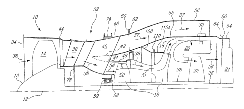
Referring to the drawings, beginning with Fig. 3, an
exemplary turbofan gas turbine engine 10 according to the
present invention includes in serial flow communication
about a longitudinal central axis 12, a fan assembly 13
having a plurality of circumferentially spaced fan blades
14, a compressor section 16 having a plurality of
circumferentially spaced low pressure compressor (LPC)
blades 50 and high pressure compressor (HPC) blades 51, a
diffuser 18, a combustor 20, a high pressure turbine (HPT)
22, and a low pressure turbine (LPT) 24. LPT 24 is
connected to the fan assembly 13 by a first or low pressure
(LP) shaft 26, and HPT 22 is connected to compressor
assembly 16 by a second or high pressure (HP) shaft 28.
Fuel injecting means 30 are provided for injecting fuel
into the combustor 20
[0048]A generally tubular casing assembly 32 having a
envelops the engine 10 and thereby defines a main flow path
36 through the core of engine 10, extending from an inlet
34 to an exhaust outlet (not shown), and a by-pass flow
path 37.
[0049] Referring to Figs. 3, 4 and 6, the casing assembly 32
according to one embodiment of the present invention
CA 02776341 2012-05-02
- 15 -
includes a generally tubular fan portion or "case" 44,
which houses the fan rotor assembly 13, a generally tubular
intercase or intermediate portion or "case" 46 downstream
of fan case 44 and a gas generator portion or "case" 52
downstream of intermediate portion 46. The intermediate
portion 46 includes a compressor shroud 48 which encircles
the blade tips of the compressor assembly 16, and a bearing
seat 58 for mounting the HP shaft bearing 59 thereto, as
will be described further below.
[0050]With reference to Figs. 5 and 6, gas generator portion
52, which is also generally tubular in shape, is for
housing the combustor 20 and perhaps HPT 22 or a section
thereof. A generally tubular case turbine and exhaust case
54 is preferably modularly provided and mounted to (i.e.
not integrated with) the aft end 107 of gas generator case
52 for housing the LPT 24, and supporting an exhaust mixer
assembly (not-shown).
[0051]The engine 10 further includes a tubular bypass duct
case 56, preferably modularly provided and mounted to (i.e.
not integrated with) the intermediate portion 46 of casing
assembly 32. The tubular bypass duct case 56 generally
surrounds the gas generator portion 52 and is radially
spaced apart therefrom, thereby defining a downstream
section of the bypass 44 therebetween.
[0052] Rather than providing a prior art segmented case, in
which the case components are removably mounted to one
another, the present invention provides a single-piece
casing assembly 32 in which all casing components are
integrally attached to one another. Referring again to
Figure 3, fan case portion 44, intermediate case portion
46, compressor shroud portion 48, bearing mount 58 and gas
CA 02776341 2012-05-02
16 -
generator portion 52 of casing assembly 32 are all
integrally joined to one another, such as by welding, or by
other process such as integral fabrication, brazing or
other methods of joining and bonding the components into
one piece. Preferably, the bypass duct case 56 is not
integrated with casing 32, in order to provide convenience
in assembly and maintenance of the engine assembly 10, and
so rather is connected by bolting together mating flanges
60 and 62 which extend radially from the respective
intermediate portion 46 and the bypass duct case 56. The
turbine and exhaust case 54, as mentioned, is also
preferably mounted to the aft end of the casing 32 by, for
example, bolting together mated flanges 64 and 66. The
bypass duct 56 and the case 54 are shown by broken lines in
Fig. 4 to distinguish them from other cases which are most
preferably integrated to form the integral case of the
present invention. Casing assembly 32 can also integrally
include the bypass and exhaust ducts, if desired.
[0053] The individual components of casing 32 are preferably
made from one material, for example steel, although a
combination of materials may be used (e.g. steel and
Inconel, etc.) as long as the desired integral bonding
technique (e.g. welding) permits such materials to be
reliably bonded together. The individual portions of the
casing are preferably made separately, as will be described
further below, which would permit, for example, a variety
of processes and materials to be used. Optionally, the
casing 32 may be formed integrally substantially in a
single operation, such as metal injection moulding.
[0054] Surprisingly, although the entire casing 32 of the
present invention may be. made from a relatively heavy
material such as steel, in very small turbofan engines
I
CA 02776341 2012-05-02
- 17 -
(i.e. preferably 2000 pounds thrust and less, more
preferably 1500 pounds thrust and less, and most preferably
about 1000 pounds thrust or less) the present invention
provides unexpected and significant benefits which directly
impact on engine SFC, as will now be described.
[0055]Firstly, even though a heavier material is used
throughout (e.g. steel versus, say, magnesium), the weight
savings from reduced flange count is surprisingly
significant. Even scaled-down flanges represent a
significant weight relative to the very small turbofan
engine, and thus it has been found that their removal
results in a disproportionate weight savings despite the
addition of weight elsewhere in the casing, contrary to the
teachings of the prior art. Therefore, contrary to the
teachings of the prior art, it has been found that a
segmented case permitting the use of lighter materials is
actually heavier in the very small turbofan range. A
beneficial redistribution of weight is therefore provided
by the present invention.
[0056] Secondly, the reduction of flange connections also
beneficially reduces tolerance stack-up by reducing tae
number of toleranced parts and connections. Accordingly,
for example by integrating the compressor bearing mount and
compressor shroud into a single part, a significantly
smaller compressor blade tip clearance may be provided.
[0057]Thirdly, the reduction of thermally mismatched parts
also permits a significant simplification to the very small
turbofan engine. In a first aspect, the reduction of
thermal mismatch improves the tolerances which must be left
in connections. In a second aspect, by improving thermal
mismatch within the casing 32, the interface with other
CA 02776341 2012-05-02
18 -
systems, such as the accessory gearbox (AGB) is greatly
simplified.
[0058] In a second aspect of the present invention, a
configuration for casing 32 is disclosed which provides
further benefits to the very small turbofan. Referring to
Figs. 4 and 5, the structure of the intermediate portion 46
of casing 32 will now be described in more detail. The
intermediate portion 46 includes an outer ring 68 having a
forward end 70 and a rearward end 71 integrated with the
radially outwardly extending bypass duct flange 60. On the
external surface of the outer ring 68 are provided
stiffening ribs 72, which reinforce the rigidity of the
outer ring 68, and engine mounts 74 which also assist in
this regard. As can be seen in Figs. 5 and 6, ribs 72 are
arranged in a grid-like manner relative to one another and
thereby divide outer ring 68 into a plurality of panels
68B. A mounting support 82 on the outer ring 68 is
provided for operatively supporting the AGB tower shaft
(not shown) , and to provide further stiffness to ring 68.
Also provided on the outer ring 68 are attachment brackets
84 for attaching the AGB. Other services, such as oil tube
inlet 83 and Ni probe boss 85, are also provided.
[0059]The intermediate portion 46 of casing 32 also includes
an inner hub 76 which has a forward end 78 and a rearward
end 80. The inner hub 76 is positioned coaxially with the
outer ring 68 and is supported within the outer ring 68 by
a plurality of casing struts 40 which are circumferentially
spaced apart and extend radially outwardly and generally
rearwardly from the inner hub 76 to the outer ring 68, as
will be described further below. The annular bearing seat
58 which receives and supports preferably the HPC bearing
59 (see Fig. 3) is integrally attached (for example, by
CA 02776341 2012-05-02
19 -
welding, as described below) to the rearward end 80 of the
inner hub 76. A mounting flange 77 is also provided on the
forward end 78 of the inner hub 76 (see Figs. 4 and 5) for
attaching a forward bearing housing (not shown) for the LP
shaft bearings.
[0060]The intermediate portion 46 of casing 32 also includes
a splitter 42, which includes an annular inner wall 85 and
an annular outer wall 86 extending axially and downstream
relative to the air flow through engine 10, divergent from
an annular leading edge tip 88. A section of the annular
bypass path 37 is thereby defined between the outer ring 68
and the annular outer wall 86 of the splitter 42, while
core flow path 36 is defined between the annular inner wall
85 of the splitter 42 and the inner hub 76. An internal web
94 is provided within splitter 42, between the inner and
outer walls 85, 86, and affixed thereto, and preferably
also affixed to struts 40, as will be described further
below. As described previously, the compressor shroud 48,
which is preferably thicker than the inner wall 85 of the
splitter 42 to withstand the demands of the compressed air
flow, is integrated (for example by welding, as described
further below) to the inner wall 85.
[0061] A plurality of circumferentially spaced apart slots 90
extend generally from near the annular tip 88 axially into
the splitter 42, for receiving the respective casing struts
40. A plurality of corresponding bosses 91 and 93 are
respectively provided, in the inner hub 76 and the outer
ring 68 for attaching the casing struts 40.
[0062] A bleed valve housing 92 (see Figs. 4 and 6) is
preferably attached by welding, to the annular outer wall
86 of the splitter 42 at its rearward end, for securing
i
CA 02776341 2012-05-02
20 -
bleed valve(s) (not shown) thereto. The intermediate
portion 46 also bleed holes 96 defined in the outer wall 86
of the splitter 42, for co-operation with an air bleed
system (not shown). Bleed holes 96 are preferably made when
fabricating the splitter 42.
(0063]Though when assembled it has the appearance of a prior
art intercase, which is most typically cast, the present
invention advantageously permits the individual components
of intermediate portion 46 may be made in accordance with a
variety of manufacturing processes. The preferred
processes will now be described. Outer ring 68 and inner
hub 76 are machined from solid. Outer ring 68 is generally
quite thin (i.e. sheet-metal-like) and, in conjunction with
stiffener ribs 72, provide intercase portion 46 with a
semi-monocoque construction which is lightweight yet
strong. Service attachments, such oil tube inlet 83 and Ni
probe boss 85, are cast (or metal injection moulded,
forged, machined, etc., as desired) and welded or brazed to
outer ring, while other "attachments" such as tower shaft
support 82 are integrally machined with the ring. Struts
40 are formed preferably in sheet metal halves (though
processes such as metal injection moulding, hydroforming,
flow forming, casting, etc. may be used) and then
integrally joined by welding to provide a hollow
configuration. One strut preferably receives an AGB tower
shaft (not shown), another the oil tube and Nl probe (not
shown), and so on. The struts 40 are preferably welded to
bosses 91 and 93 and within slots 90, to thereby assemble
outer ring 68, splitter 42 and inner hub 70 to provide
intercase portion 46 of casing 32.
[0064] Referring to Figure 9, in an alternate embodiment,
intercase portion 46 may have struts 40 which have a
CA 02776341 2012-05-02
21 -
configuration which provides a modified joint with splitter
42 and outer ring 68, through the inclusion of flanged
components 40A and 68A which may be welded to struts 40 and
outer ring 68 respectively. Such flanged components may be
provided to facilitate stronger connection welds, etc. and
thus this embodiments further illustrates the flexibility
the present invention gives the designer.
[0065]The individual components are integrated together
preferably by welding (or other integral joining technique
of the general types already mentioned) to provide the
integrated intermediate portion 46, and this is preferably
before integrating the intermediate portion 46 with the
other portions of the casing 32 (i.e. fan portion 44,
etc.). The details of the intermediate portion 46 may vary
depending on various embodiments used for various engine
models.
[0066] Referring to Figs. 4 and 6, the fan portion 44
includes an annular upstream section 98 encircling the fan
blades 14 (see Fig. 3). The upstream section 98 is
preferably strong enough to ensure containment of a blade-
off incident, or incorporate an insert therefor (not
shown). The fan case 44 includes a downstream section 100
which extends from the upstream section 98 to a downstream
edge 103. The downstream section 100 incorporates slots 101
which locates and supports the outer end of fan exit vanes
38, as will be described below.
[0067] Referring to Figure 10, the stator-less fan exit vanes
38 are slidingly inserted preferably from outside the fan
portion 44 and therefore slots 101 are defined accordingly
in the section 100 of the fan portion 44 (see Fig. 6) and
in the inner shroud 102. The fan exit vanes 38 are
CA 02776341 2012-05-02
22 -
releasably mounted between the section 100 of the fan
portion 44 and the inner shroud 102 at the. corresponding
slots, , and releasably retained therein by pliable
compression-fit insert grommets 120 (see Fig. 11) and
straps 122.
[0068] Fan portion 44 may be flow-formed from one material,
such as steel, nickel or inconel. Alternate fabrication or
forming techniques may also be used, and one or more
materials may be used.
[0069] The fan portion 44 is integrated into the intermediate
portion 46 by integrally joining, preferably by welding,
the aft end 103 of fan case portion 44 with the forward end
70 of the outer ring 68 of the intermediate portion 4 to
thereby create an integral joint 130 (see Fig. 4) The
inner shroud 102 of the fan portion 44 is also attached to
the inner hub 76 of the intermediate portion 46, preferably
by welding at 132. The inner shroud 102 and the fan exit
vanes 38 are preferably not integrated with the casing
assembly 32, but rather are releasably mounted to the fan
portion 44 as described above after the fan portion 44 is
integrated with the intermediate portion 46.
[0070]The gas generator case portion 52 of casing 32,
includes a upstream section 104 and a substantially
cylindrical downstream section 106 which are integrated
together, preferably by being fabricated in a single
manufacturing process. An integral inner ring 108 is
disposed within the upstream section 104 and is integrated,
preferably by welding, with the gas generator case 52 at
the forward end thereof. A mounting flange 110 extends
radially outwardly from the inner ring 108 at the inner
edge thereof, for securing the diffuser 18 flange 11OA and
CA 02776341 2012-05-02
23 -
bleed valve 150 thereto (see (Fig. 3, 4 and 12) A number
of openings 140 (see Fig. 6) are provided in the gas
generator case 52 for receiving or mounting engine
components of the gas generator portion, such as fuel
injecting means 30, and so on, as will be understood by one
skilled in the art. The downstream cylindrical section 106
has an aft end 107 which is integrated with a radially
outwardly extending mounting flange 112, for connection
with turbine and/or exhaust case 54. The gas generator
case 52 is integrated at the front end thereof with the aft
end 89 of the annular outer wall 86 splitter 42 of the
intermediate portion 46 at 134, also preferably by welding.
[0071]The fan portion 44, the intermediate portion 46 and
the gas generator portion 52 of casing 32 are thus
fabricated separately, for example by machining from solid,
sheet metal fabrication, forging, casting, flow-forming,
etc., depending on the design of each and the wishes of the
designer. The separately fabricated cases are then
integrally attached preferably by welding. It is then
preferable to finally machine the interior portions of the
integrated. casing 32 prior to installation of rotor
assemblies, in order to reduce any tolerance stack-up
occurring during casing 32 manufacture or assembly. This
dramatically reduces the tolerance stack-up over prior art
devices.
[0072] The way in which each portion is formed and the exact
means by which the portions are attached are not critical
to the invention, but rather may be left to the designer's
discretion. Therefore, the present invention allows for
flexibility in selection of manufacturing processes to meet
the designer's needs in providing an integrated case
assembly for a very small turbofan engine. The present
CA 021776341 2012-05-02
24 -
invention thereby permits a variety of manufacturing
techniques, notably among them fabrication techniques such
as machining from solid, flow-forming and sheet metal
construction, which are not available with prior art casing
designs.
[0073]In yet another aspect of the present invention, the
flexibility of manufacture permitted by the present
invention permits the bearing mounts integrally provided in
the case to be much simpler, in terms of part count, than
prior art bearing mounts. Typical prior art gas turbine
engines require complicated bearing mounts, including
assemblies known as "squirrel cages" to dampen vibrations
caused by rotor imbalances which inevitably result despite
highly accurate machining processes. In the present
invention however, bearing mounts such as bearing mount 58
may be provided with an integrated flexibility, such that
which is a function of its material, configuration,
stiffness, etc., such that bearing mount 58 itself can be
"tuned" during manufacture to thereby obviate the need for
a squirrel cage. The bearing mount 58 is thus integrally
designed and provided to also perform a damping function to
remove the need for separate squirrel cage assemblies.
Since squirrel cages add weight, length and complexity to
the engine, deleting this component is of course valuable
and therefore yet another beneficial feature of the present
invention.
[0074] Referring now to Figs. 5, 6 and 12, in a yet further
aspect of the present invention, a method for assembling a
turbofan engine will now be described. Unlike the prior
art, the present invention casing 32 is preferably fully
(or substantially) assembled before any rotating or other
gas turbine components are assembled therein. Thus, the
CA 02776341 2012-05-02
25 -
first step is making and assembling the components of the
casing assembly 32, as described above. The next step, also
described above, preferably is to machine internal surfaces
of the casing 32, such as surfaces relating to bearing
mounts, compressor shrouds and similar surfaces, to remove
any accumulated tolerance stack-up which would affect the
efficient operation of the engine. The next steps are to
insert the fan rotor assembly 13 inside casing 32 (step not
shown in the Figures), preferably through the inlet 34 of
the casing assembly 32 and into the fan portion 44, and to
insert the bleed valve 150 and compressor assembly 16 into
casing 32, preferably through gas generator portion 52 (see
Fig. 12). The diffuser 18, combustor 20, the turbine
assemblies, and other components are also inserted into
casing 32, also preferably from the aft end of the gas
generator portion 52. The assembly process of the engine
is then completed by further mounting the turbine and
exhaust case 54, the bypass duct 56, and other engine
components in and to the casing assembly 32. While the
specific order of insertion and assembly of these interior
assemblies in casing may depend on preference or the design
layout of engine 10, the present invention involves
building the core of engine 10 inside a completed or
substantially completed casing 32, thereby permitting an
overall more efficient assembly technique for the gas
turbine engine.
[0075]The present method also advantageously provides a fast
assembly of a gas turbine engine because no fixtures such
as flange connections are required and therefore, less
"final" assembly steps are required.
[0076]As mentioned, the present invention has particular
application for use in so-called very small gas turbine
CA 02776341 2012-05-02
26 -
engines, namely engines typically 2000 pounds thrust and
below for use in general aviation aircraft sometimes
referred to as "personal" jet aircraft. This market
represents a leading edge of gas turbine turbofan
technology, wherein the limits of scaling and cost-
effective design and operation are challenged. Prior art
small turbines, such as those used in missile engines are
simply unsuitable. Missile engines are invariably
expensive to make and operate (owing to their military
heritage), and are designed for extremely short operational
lives (a few hours) in which they are continuously operated
at full thrust. The very small turbofan as contemplated
herein, however, must of course be operated intermittently
at varying thrust levels (e.g. idle, taxi, take-off, climb,
cruise, approach and landing) for thousands of hours, not
to mention be affordable and quiet to operate and
environmentally friendly. Likewise, although microturbines
are beginning to proliferate in the power generation field,
this technology is also largely unsuitable since aircraft
applications require extremely lightweight and reliable
designs which are typically not found in industrial
microturbine designs. Accordingly, the present invention
represents an advance in the field of providing an
affordable-to-operate turbofan to general aviation pilots.
[0077] The present invention permits a turbofan casing to be
provided which, in the very small turbofan size range,
permits the overall weight of the casing to be reduced over
conventional larger designs. The weight reduction is due
in part to the thin shell stiffened semi-monocoque design
of the intermediate case section 46, which has an
integrally-stiffened thin shell construction which allows
the designer to optimize the use of metal to thereby reduce
weight. Referring again to Figs. 5, 6 and 7, the thin
CA 02776341 2012-05-02
27 -
"sheet" outer ring "panels" 68B are reinforced at specific
locations by the ribs 72 and struts 40, and by engine
mounts 74 and other similar features on the ring 68, to
balance external loading by compression and tension in the
reinforcing members reacting balanced shear in the "panels"
68B of the outer ring 68. This provides a stable structure
with a stiffness comparable to a cast structure more than
500% thicker. It is through this approach, combined with
the simplicity of attachment, that the overall weight of
the casing is significantly reduced.
[0078]Referring again to Figs. 5 6 and 7, as described
above, outer ring 68 has a thin-walled semi-monocoque
design includes a plurality of ribs 72 extending axially
and circumferentially about the outer ring 68 to thereby
define a plurality of thin-shell panels 68B therebetween.
The axial and circumferential arrangement of ribs 72
provides panels 68B with a generally rectangular shape and
the ribs being more or less parallel or perpendicular to
one another. A partial top view of outer ring 68 is shown
in Figure 14, showing ribs 72 and thin-shell panels 68B.
[0079]The splitter 42 separates core flow passage 36 from
bypass flow passage 37, and is supported by. Each strut 40
extends from a leading edge 40A to trailing edge 40B, the
trailing edge having a bent, kinked or discontinuous
profile having an inner portion 40C and an outer portion
40D joined by a bend or kink 40E. Each strut 40 extends
from an inner end to an outer end (not indicated) to meet
with and connect to bosses 93 and 91, respectively,
integrally provided on inner and outer rings.
[0080] Referring now to Figure 13, the splitter 42 is joined
to the strut 40 and includes the internal web 94 (see also
CA 02776341 2012-05-02
- 28 -
Figs. 3-5) which co-operates with struts 40 and splitter 42
to thereby define a plurality of closed-section hollow
torque boxes 41 between adjacent struts 40 (see also Fig.
15). In the example engine depicted in Figure 15,
therefore, since there are six struts there are six torque
boxes 41 formed therebetween. Struts 40, splitter 42 and
web 94 are joined to one another by shear-transmitting
joints (e.g. welded, brazed, or other bonded joint, or have
an integral construction and hence not be "joints" per se).
The joints (indicated by 42A and 94A in Fig. 16a) are
preferably strong enough provide the necessary shear
connections to prevent deformation of the torque boxes
under anticipated loadings, as will be described below.
These torque boxes provide the mechanism for transferring
the bending moments associated with the weight of the
engine core transferred from the gas generator case to the
splitter (see Figs. 3, 4, and 6, for example).
[0081] The splitter 42 preferably further includes a
circumferential stiffening ring 43 slightly aft of torque
box 41. Similarly, the inner hub 76 preferably includes a
pair of circumferential stiffening rings 76A, and 76B,
respectively, on an interior side thereof, and preferably
axially positioned to correspond to the locations at which
struts 40, boss 91 meet inner hub 76. The Inner hub 76
supports the main low spool thrust bearings at bearings
57and also includes a bearing attachment seat 58 and a
bearing bumper 58A, a.5 will be described in more detail
below.
[0082]Mounts 74 are preferably positioned relative to struts
40 such that mounts 74 are substantially aligned with a
centroidal axis "CA" (see Fig. 12) of strut 40 to thereby
significantly reduce any tendency for loads to cause strut
CA 02776341 2012-05-02
29 -
bending relative to the mounts 74. The 'centroidal axis'
will be understood to mean a line passing through the
centroids of all axial sections of a strut 40 (i.e. will
pass through the centroid of any horizontal section of the
strut 40, as viewed in Fig. 13).
[0083]As mentioned above, outer ring 68, which is a semi-
monocoque structure composed of thin-shell shear panels
68B, and axial and circumferential stiffeners 72, is thus
analogous to conventional aircraft fuselage turned inside-
out. The loads applied to the structure are reacted as
either tension or compression (depending on the direction
of the source load) in the ribs 72, which are internally
balanced by opposing shears in the panels 68A. Stresses
are thus shared amongst adjacent ribs 72, and bending
forces are avoided by resolution to in-plane tensile and
compressive forces and shear. This manner of reacting
loads in shear gives the intermediate case portion 46 a
relatively high structural efficiency and stiffness
compared to a typical prior art cast engine case. In the
design described, engine mounts 74 and strut bosses 93 also
act as tensile/compressive .load bearing members
communicating with adjacent shear panels. Loads thus enter
the outer ring 68 via the struts 40/bosses 93, and are
passed through the semi-moncoque structure or ribs and
shear panels to the engine mounts 74, for ultimate
transmission to the aircraft. Since out-of-plane bending
forces are resolved into in-plane compressive/tensile
loads, the think prior art case sections are not required
as bending is no longer reacted merely by the casing
section in plate bending. The result is a casing which is
significantly lighter than the prior art, particularly when
high modulus materials are used, such as steel. Although
the ribs & panel configuration shown in Figure 14 is
CA 02776341 2012-05-02
- 30 -
preferred, the grid need not be regular nor rectangular,
but rather any effective configuration preferred by the
designer may be used.
[0084] Similar to outer ring 68, inner hub 76 is also
provided with a semi-moncoque structure, as follows.
Stiffener rings 76A and 76B and strut bosses 91 co-operate
to divide the annular surface of hub 76 into a plurality of
thin-shell shear panels 76C which react tensile or
compressive loads in rings 76A, 76B and strut bosses 91 as
a shear in panels 76C, as depicted in Fig. 17, to thereby
balance the structure. - In this manner, bending in the
inner hub is minimized such that the panels 76C may be
substantially thinner than the prior .art (e.g. the present
invention may have panels of 0.050" or less) A bearing
bumper 58A may also be provided to reduce bending, as is
described further below.
[0085] In use, bearing loads exerted on inner hub 76 are
transferred to outer ring 68 via struts 40, as follows. In
general, bearing loads generated by engine thrust and
transient dynamic events, such as blade-off events or bird
strikes, are experienced mainly at bearing set 57 (bearing
58 typically contributes little additional loading in such
events) which are passed into the inner hub 76 at its
leading edge. The inner hub, with its semi-moncoque
design, reacts the applied loads internally as
tension/ compression and shear, as described above. The
bearing load is passed mainly through the leading edge 40A
of the strut 40 in compression or tension to the mount pads
74. For reasons described below, the mount pads 74 are
located at (or near) the centroidal axis CA of the strut 40
cross-section.
CA 02776341 2012-05-02
31 -
[0086] In use, engine inertia loads are also exerted on the
splitter 42 by the remainder of the engine connected
thereto via the gas generator case, and these are
transferred to outer ring 68 via struts 40. In general,
engine inertia loads enter the intermediate case 46 via the
splitter (to which the gas generator case is attached) and
are reacted in the rear outer portion 40D of the strut 40
as a compression or tensile load. These loads tend to bend
the strut and torque box and thus are reacted into the
structure of strut 40 by the reaction of torque box 41
converting the load into a shear which stiffener 94
transmits as a tension or compression into the rear of the
strut. The torque boxes 41 will now be described in more
detail.
[0087]The torque boxes 41 are hollow closed cells formed
between the struts 40, splitter 42, and stiffener 94. As
will become apparent below, torque boxes 41 are somewhat
similar in purpose and function to the torque box present
in an aircraft wing, although here the construction is
analogous to an aircraft wing wrapped into a cylinder. The
rear stiffener web 94, it will be seen, is analogous to the
spar of this cylindrical wing. The torque boxes 41
"convert" loads applied to one or more struts (for example,
a bending moment and a transverse shear) into a balanced
shear flow in the cell, which may then be "communicated" to
and reacted by adjacent struts, as will now be described.
[0088] Referring to Fig. 15, 16a and 16b, a load, such-as a
bending moment, in one direction on one strut 40 will be
communicated by the torque.boxes 41' to the two adjacent
struts 40', which will in turn of course react the force,
thus tending reduce the effect of the applied load on the
first strut by transferring a reactionary component to the
CA 02776341 2012-05-02
3G -
adjacent struts. In this manner load sharing is achieved.
(Though only the interaction of three struts is shown in
Fig. 16b for description purposes, it will be understood
that struts 40' likewise communicate external and internal
loads to their adjacent neighbours via their respective
torque boxes, and thus external and internal loads are thus
redistributed around the structure among the struts 40.)
Referring still to Fig. 16a, and as will be discussed in
more detail below, a torsional load applied to torque box
41 (represented by the circular stippled arrow), such as
that applied by the weight/inertia of the gas generator
attached to the splitter, is also reacted by the torque box
41, in this case preferably mostly as a shear force, which
is passed to strut 40 as an in-plane load at least
partially by a shear (represented by the straight stippled
arrow) passed through the shear transmitting joint 94A from
web 94 to strut 40. The stiffener ring 43 helps to
distribute the inertia loads more uniformly to the torque
boxes 41. The torque box arrangement and structure
therefore both helps distribute loads among adjacent struts
as well as convert torsional and bending loads into shear,
which can then be transmitted as substantially pure
(preferably) compression or tension in struts 40.
[0089] Therefore, since the struts are inherently connected,
any tendency for displacement of one strut is inherently
reacted and balanced through the torque boxes by adjacent
struts, which not only redistributes the load but also
substantially reduces the amount of bending forces on the
struts, even during transient dynamic events such as bird
strikes. This significant reduction of bending forces which
permits the use of thin-walled structures of the struts of
the present invention, since the absence of plate bending
CA 02776341 2012-05-02
33 -
permits substantial reduction in cross-sectional thickness
in the casing and struts relative to the prior art.
[0090]Referring still to Fig. 16a, the in-plane loads
transferred from torque box 41 to strut 40 will thus load
the aft portion 40D of the strut 40 in tension or
compression (depending on load direction) and this internal
tensile or compressive load is then carried by the aft
portion 40D of the strut 40 to the outer ring 68 and
ultimately the engine mount 74. The shape of the strut 40
is used to divide the bearing loads from the inertia loads.
In particular, the bend or kink 40E in the aft portion 40B
of the strut 40 reduces the axial stiffness of the strut 40
which thus creates two separate load paths for the loads
generated in the engine (i.e. one for bearing loads and one
for inertia loads, as described above). The kinked shape
of the strut 40 interrupts the load path to the inner hub,
which thereby impedes the transfer of loads from the
splitter to the hub. This simplifies load transfer as will
as beneficially reducing bending on the strut, which
thereby permits a thin-walled strut structure to be
employed. Referring to Figs. 18a and 18b, since prior art
struts were required to react bending forces transmitted
thereto, the prior art struts required thick enough
sections (Fig. 18b) to provide the appropriate bending
strength. In the present invention, however, the
reduction, or more preferably negation, of bending of strut
40 permits the use of sheet metal struts (Fig. 18a) which
are of course much lighter than the prior art.
[0091]As described above, the engine mounts are preferably
positioned along (or as close as is possible) the
centroidal axis, thereby negating (or reducing -to a
manageable level) the bending moment applied to
CA 02776341 2012-05-02
34 -
intermediate case 46 as a result of the tensile/compressive
loads passed to the intermediate case 46 from struts 40.
In this manner, bending is reduced on intermediate case 46
and struts 40, further enhancing the opportunity to make
full advantage of the semi-monocoque and thin-walled design
of the case and struts to thereby maximize structural
efficiency and minimize weight. The structural efficiency
of the semi-monocoque structure of the inner hub 76 and
outer ring 68 is thereby improved and enhance by the use of
the struts 40 of the present invention, and although these
components may be employed individually with advantage, the
use of two or more, and preferably all three together
provides yet further advantages and benefit by the
intrinsic co-operation therebetween which may be obtained.
[0092]It should be noted that, as described above, the
balanced shear flow, induced in the torque boxes 41 as a
result of a torsional load, is reacted by the struts 40
predominantly as shear load at the splitter/strut joints
(42A, 94A). Thus, there is a substantial absence of
tensile loads at these joints, which advantageously permits
the use of fillet welds to provide joints 42A, 94A.
Also, due to the relatively long length of these joints,
and loading sharing among the plurality of joints in the
overall structure (i.e. on the plurality of torque boxes),
the shear stresses on the joints are relatively low, thus
further allowing a reduction of the thickness the strut and
torque box cross-section. Very thin gauges of sheet metal
may thus be used.
[0093]Advantageously, the struts may be designed to act as a
load "fuse" limiting the allowable load transmitted to the
mount by their compressive capability. (It will be
understood that when a sufficient compressive load is
CA 02776341 2012-05-02
35 -
applied to the thin-walled strut, the strut will collapse).
For example, the strut may be designed to collapse when a
certain threshold load is experienced (e.g. a significant
big strike) to thereby limit the amount of load (and
therefore damage) which is transferred to the aircraft in
such an event. In this example taken in the context of the
preferred embodiment above, when the threshold bearing load
is applied by the inner hub to the strut, the leading edge
is designed (i.e. by virtue of its thickness, etc.) to
collapse under such event loads, thereby absorbing energy
by plastic deformation rather than transferring it to the
engine mounts and aircraft. In design, the maximum
allowable load to be transferred by the strut would be
determined, and then a strut configuration is determined
that would collapse or otherwise structurally fail upon the
application of this maximum load, or a~larger load, and
thereby limit the load transfer to the engine mounts.
[0094] Referring again to Fig. 13, the bearing bumper 58A can
be provided to assist in improving the stiffness of inner
hub 76. For example, sizable asymmetric bearing loads are
applied to inner hub 76 during medium-sized bird strike
events, for example, which tend to cause bending in the
engine shafts, which tend to distort the bearing housing,
and thus bearing seat 58. The bumper 58A is a leg or stop-
type device which is provided with a small clearance (not
shown, as the scale of Fig. 13. is to small to indicate
this feature) between the bumper 58A and the bearing seat
58 (or bearing or other appropriate surface). The
clearance preferably corresponds to the amount of allowable
deflection desired in such an event (e.g. 0.005", for
example). If a larger deflection is forced, the bumper
will assist the bearing seat 58 (or whatever surface is
opposed by bumper 58A) to resist such deflection. This
CA 02776341 2012-05-02
36 -
simple device therefore permits the rear portion of the
inner hub 76 (i.e. the portion supporting the bearing seat
58) to be substantially thinner, since the inner hub 76
thickness does not need to react these bending forces and
deflections alone. This therefore also helps unload the
bottom and rear portion of the strut 40, so that the inner
hub 76 and bearing seat 58 can be thinner, and less weight.
[0095]Although the individual weight savings achieved by
each aspect of the present invention may be insubstantial
when considering larger turbofan engines, in the case of
very small turbofan engines (e.g. 2000 pounds thrust and
under), these accumulations of small weight savings result
in a significant weight savings.
[0096]The invention provides a multi-faceted structure which
seeks to force out-of-plane loads (e.g. bending loads) back
into plane, and balances tensile and compressive loads with
shear panels to thereby create equal and opposite shear
flows in adjacent panels.
[0097]In this application, "thin wall" means sheet metal
type thickness, wherein "thin" is interpreted relative to
the applied loads, such that the thin wall is substantially
incapable of reacting applied bending forces in plate
bending.
[0098]While the above description addresses the preferred
embodiments, it will be appreciated that the present
invention is susceptible to modification and change without
departing from the scope of the accompanying claims. For
example, while described in respect of an application to
very small turbo fan, engines, some benefits may be attained
in larger turbofan or other gas turbine engines in applying
the principles of the present invention. Though the use of
CA 02776341 2012-05-02
37 -
certain materials and manufacturing methods have been
disclosed as preferred, other materials and methods may be
substituted without departing from the present invention.
The cases need not be integrated as described to achieve
benefits of the present invention. Likewise the struts
need not necessarily be hollow in all embodiments, nor need
they comprise a single "cell" as described above, but may
have multiple cells defined therein (see Fig. 19) As
shown in Fig. 16c, the torque box may comprise more cells,
The torque box need not be comprised of the splitter
itself, but may be an additional structure which may be
inside the splitter, or elsewhere. Although a single strut
is preferred for transfer of both bearing and inertia
loads, multiple struts (e.g. an upstream and downstream
strut pair) may be sued) . The semi-monocoque shear panels
in ring 68 and hub 76 need not be rectangular or regularly
sized. Still other modifications will be apparent to those
skilled in the art which will fall within the scope of the
invention intended by the inventors, and the appended
claims therefore are not intended to exclude such
modifications.