Note: Descriptions are shown in the official language in which they were submitted.
CA 2776382 2017-03-17
REMOVAL OF AN ACCUMULATED FROZEN SUBSTANCE FROM A
COOLING UNIT
SUMMARY
[2] This Summary is provided to introduce, in a simplified form, a
selection
of concepts that are further described below in the Detailed Description. This
Summary is not intended to identify key features or essential features of the
claimed subject matter, nor is it intended to be used to limit the scope of
the
claimed subject matter.
[3] An embodiment of a probe includes a sensor and a support. The sensor
is operable to provide an indication of a thickness of a frozen substance that
has
accumulated between the sensor and a cooling fin of a cooling unit, and the
support is operable to hold the sensor spaced apart from the cooling fin.
[4] For example, a defrost controller may use an embodiment of such a
probe to monitor an amount of frost build up on the fin or fins of a cooling
unit (e.g.,
a refrigeration or freezer unit) so that the controller may initiate a defrost
cycle only
when needed. Such a probe may be more reliable than other defrost-detection
techniques, and such a defrost controller may increase the cooling and energy
efficiencies of a cooling unit as compared to a cooling unit having a
conventional
defrost controller.
[4a] There is described a detection unit, comprising: a probe including a
frozen-substance sensor configured to provide an indication of a thickness of
a
frozen substance formed between the sensor and a first cooling fin of a
cooling
unit; and a processor configured to generate an indication that the cooling
unit is
ready for removal of at least part of the frozen substance in response to the
thickness of the frozen substance being greater than a threshold thickness;
wherein the probe is configured to generate a signal as the indication of the
thickness of the frozen substance, the signal corresponding to a value of
1
CA 2776382 2017-03-17
capacitance between the sensor and the fin; and wherein the processor is
configured: to generate an indication that the cooling unit is ready for
removal of at
least part of the frozen substance in response to the signal corresponding to
a
capacitance value that has a predetermined relationship to a capacitance
threshold value that corresponds to the threshold thickness; to determine a
first
post-defrost capacitance value corresponding to the signal; to adjust the
capacitance threshold value in response to the first post-defrost capacitance
value;
to determine a second post-defrost capacitance value in response to the signal
after determining the first post-defrost capacitance value; and to adjust the
capacitance threshold value in response to the second post-defrost capacitance
value if the second post-defrost capacitance value is less than the first post-
defrost
capacitance value.
[4b] There is also described a frozen-substance-removal controller,
comprising: a detection unit including: a probe including a frozen-substance
sensor
configured to provide an indication of a thickness of a frozen substance
formed
between the sensor and a first cooling fin of a cooling unit; and a processor
configured to generate a first indication that the fluid-cooling unit is ready
for
removal of at least part of the frozen substance in response to the thickness
of the
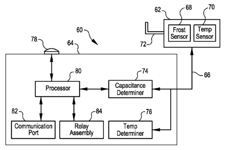
frozen substance being greater than a threshold thickness; wherein the probe
is
configured to generate a signal as the indication of the thickness of the
frozen
substance, the signal corresponding to a value of capacitance between the
sensor
and the fin; and wherein the processor is configured: to generate an
indication that
the cooling unit is ready for removal of at least part of the frozen substance
in
response to the signal corresponding to a capacitance value that has a
predetermined relationship to a capacitance threshold value that corresponds
to
the threshold thickness; to determine a first post-defrost capacitance value
corresponding to the signal; to adjust the capacitance threshold value in
response
to the first post-defrost capacitance value; to determine a second post-
defrost
capacitance value in response to the signal after determining the first post-
defrost
capacitance value; and to adjust the capacitance threshold value in response
to
1 a
CA 2776382 2017-03-17
the second post-defrost capacitance value if the second post-defrost
capacitance
value is less than the first post-defrost capacitance value; and a controller
configured to cause the cooling unit to initiate a frozen-substance-removal
cycle in
response to the indication from the processor.
[4c] There is
also described a cooling system, comprising: a first cooling unit
having at least one first cooling fin on which may form a frozen substance
having a
thickness; a first probe including a frozen-substance sensor disposed adjacent
to
one of the at least one first cooling fin and configured to provide an
indication of
the thickness of the frozen substance by indicating a capacitance that is
dependent on the thickness of the frozen substance formed between the sensor
and the one of the at least one first cooling; a first processing circuit
configured to
generate a first indication that the cooling unit is ready for removal of at
least part
of the frozen substance in response to the thickness of the frozen substance
being
greater than a threshold thickness; wherein the first probe is configured to
generate a signal as the indication of the thickness of the frozen substance,
the
signal corresponding to a value of the capacitance; and wherein first the
processing circuit is further configured: to generate the first indication
that the
cooling unit is ready for removal of at least part of the frozen substance in
response to the signal corresponding to a capacitance value that is greater
than a
capacitance threshold value that corresponds to the threshold thickness; to
determine a first post-defrost capacitance value corresponding to the signal;
to
adjust the capacitance threshold value in response to the first post-defrost
capacitance value; to determine a second post-defrost capacitance value in
response to the signal after determining the first post-defrost capacitance
value;
and to adjust the capacitance threshold value in response to the second
post-defrost capacitance value if the second post-defrost capacitance value is
less
than the first post-defrost capacitance value; and a first controller
configured to
cause the first cooling unit to initiate a frozen-substance-removal cycle in
response
to the first indication from the processing circuit.
lb
CA 2776382 2017-03-17
[4d] There is also described a facility, comprising: a space; and a cooling
system configured to cool the space, the cooling system comprising: a first
cooling
unit having at least one first cooling fin on which may form a frozen
substance
having a thickness; a first probe including a frozen-substance sensor disposed
adjacent to the fin and configured to provide an indication of the thickness
of the
frozen substance by forming a capacitance with one or more of the at least one
first cooling fin; wherein the first probe is configured to generate a signal
as the
indication of the thickness of the frozen substance, the signal corresponding
to the
value of the capacitance; a first processing circuit configured to generate a
first
indication that the cooling unit is ready for removal of at least part of the
frozen
substance in response to the signal corresponding to a capacitance value that
has
a predetermined relationship to a capacitance threshold value that corresponds
to
the thickness of the frozen substance being greater than a threshold
thickness;
wherein first the processing circuit is further configured: to generate the
first
indication that the cooling unit is ready for removal of at least part of the
frozen
substance in response to the signal corresponding to a capacitance value that
is
greater than a capacitance threshold value that corresponds to the threshold
thickness; to determine a first post-defrost capacitance value corresponding
to the
signal; to adjust the capacitance threshold value in response to the first
post-defrost capacitance value; to determine a second post-defrost capacitance
value in response to the signal after determining the first post-defrost
capacitance
value; and to adjust the capacitance threshold value in response to the second
post-defrost capacitance value if the second post-defrost capacitance value is
less
than the first post-defrost capacitance value; and a first controller
configured to
cause the first cooling unit to initiate a frozen-substance-removal cycle in
response
to the first indication from the processing circuit.
[4e] There is also described a method, comprising: receiving an indication
of
a thickness of a frozen substance formed over a first cooling fin of a cooling
unit in
response to a sensed capacitance formed by an electrode and the first cooling
fin;
indicating that the cooling unit is ready for melting of at least part of the
frozen
c
CA 2776382 2017-03-17
substance in response to the thickness of the frozen substance being greater
than
a threshold thickness; wherein receiving the indication comprises receiving a
signal
that indicates a value of capacitance for a capacitor formed between the first
cooling fin and the electrode; wherein indicating comprises indicating that
the
cooling unit is ready for melting of at least part of the frozen substance in
response
to the signal corresponding to a capacitance value having a predetermined
relationship to a threshold capacitance value that corresponds to the
thickness
threshold; determining a first post-melting capacitance value corresponding to
the
signal; adjusting the capacitance threshold value in response to the first
post-melting capacitance value; determining a second post-melting capacitance
value in response to the signal after determining the first post-melting
capacitance
value; and adjusting the threshold capacitance value in response to the second
post-defrost capacitance value if the second post-melting capacitance value is
less
than the first post-melting capacitance value.
[4f] There is also described a method, comprising: receiving a signal
representing a first capacitance value from a sensor while the sensor is
remote
from a fin of a cooling unit, the first capacitance value corresponding to a
capacitance offset; receiving the signal representing a second capacitance
value
from the sensor while the sensor is adjacent to the fin and while the fin is
approximately free of the frozen substance, the second capacitance value
corresponding to a no-frozen-substance-accumulation capacitance value; and
determining from the first and second capacitance values a third capacitance
value
corresponding a threshold thickness of a frozen substance that may form over
the
fin.
[4g] There is also described a method, comprising: receiving a first
capacitance value associated with a sensor while the sensor is remote from a
fin of
a cooling unit; receiving a second capacitance value associated with the
sensor
while the sensor is adjacent to the fin; generating a third capacitance value
substantially equal to a difference between the first and second capacitance
values; calculating a fourth capacitance value that corresponds to a threshold
id
CA 2776382 2017-03-17
thickness of a frozen substance that may form over the fin, the fourth
capacitance
value being a function of the third capacitance value, the threshold
thickness, and
a dielectric constant of the frozen substance; receiving a fifth capacitance
value
associated with the sensor after calculating the fourth capacitance value and
while
the sensor is adjacent to the fin; and causing the cooling unit to execute a
defrost
cycle in response to the fifth capacitance value equalling or exceeding the
fourth
capacitance value.
le
CA 02776382 2012-03-30
WO 2011/041780 PCT/US2010/051317
BRIEF DESCRIPTION OF THE DRAWINGS
[5] FIG. 1 is a schematic diagram of an embodiment of a cooling
unit.
[6] FIG. 2 is a plan view of a pattern of an accumulation of a
frozen substance on the fins of a cooling unit.
[7] FIG. 3 is a plan view of another pattern of an accumulation of a
frozen substance on the fins of a cooling unit.
[8] FIG. 4 is diagram of an embodiment of a cooling system
having multiple cooling units.
[9] FIG. 5 is a block diagram of an embodiment of a
frozen-substance detection unit.
[10] FIG. 6 is a schematic diagram of an embodiment of a
capacitance-detection circuit that the capacitance determiner of FIG. 5 may
incorporate.
[11] FIG. 7 is a plan view of an embodiment of a frozen-substance
probe attached to a fin of a cooling unit, where on the fin is an accumulation
of a frozen substance.
[12] FIG. 8 is a plan view of an embodiment of a frozen-substance
probe attached to a fin of a cooling unit, where on the fin is an artifact
that
may affect the measurement of an accumulation of a frozen substance.
[13] FIG. 9 is a plan view of another embodiment of a
frozen-substance probe attached to a fin of a cooling unit, where on the fin
is an accumulation of a frozen substance.
[14] FIG. 10 is a plan view of an embodiment of the
frozen-substance probe of FIG. 7 attached to a fin of a cooling unit, where
the pattern of frozen-substance accumulation on the fin is different from the
pattern of frozen-substance accumulation in FIG. 7.
2
CA 02776382 2012-03-30
WO 2011/041780 PCT/US2010/051317
[15] FIG. 11 is a plan view of an embodiment of the
frozen-substance probe of FIG. 9 attached to a fin of a cooling unit, where
the pattern of frozen-substance accumulation on the fin is different from the
pattern of frozen-substance accumulation in FIG. 9.
[16] FIG. 12 is a plan view of another embodiment of a
frozen-substance probe.
[17] FIGS. 13A-13C are respective side, plan, and cutaway plan
views of an embodiment of a cooling fin, and FIG. 13D is a cutaway plan
view of an embodiment of a frozen-substance probe mounted to the fin.
[18] FIG. 14 is a plan view of cooling fins and another embodiment
of a frozen-substance probe mounted to the fins.
[19] FIG. 15 is a plan view of cooling fins and another embodiment
of a frozen-substance probe mounted to the fins.
[20] FIG. 16 is a plan view of cooling fins and yet another
embodiment of a frozen-substance probe mounted to the fins.
[21] FIG. 17A is a plan view of an embodiment of cooling fins, and
FIG. 17B is a plan view of an embodiment of a frozen-substance probe
mounted to one of the cooling fins of FIG. 17A.
[22] FIG. 18 is a cutaway side view of an embodiment of a cooling
tube, an embodiment of a cooling fin, and an embodiment of a
frozen-substance probe mounted to the cooling fin.
[23] FIG. 19 is a block diagram of an embodiment of the
cooling-unit controller of FIG. 1.
[24] FIG. 20 is a block diagram of an embodiment of a space
cooling system that incorporates an embodiment of the cooling-unit
controller of FIG. 19.
[25] FIG. 21 is a block diagram of a facility cooling system that
incorporates an embodiment of the space cooling system of FIG. 20.
3
CA 02776382 2012-03-30
WO 2011/041780 PCT/US2010/051317
[26] FIG. 22 is a block diagram of another embodiment of a cooling
unit that incorporates an embodiment of the frozen-substance detection unit
of FIG. 5.
[27] FIG. 23 is a cut-away side view of an embodiment of a cooling
tube and an embodiment of a frozen-substance probe of the cooling system
of FIG. 22.
DETAILED DESCRIPTION
[28] FIG. 1 is a block diagram of a cooling unit 10, which may be,
for example, a refrigeration or freezer unit for a warehouse in which
perishable items are stored.
[29] The cooling unit 10 includes an internal fin-and-tube assembly
(sometimes called an evaporator-coil assembly) 12, a fan assembly 14,
input and discharge ports 16 and 18, a valve assembly 20, a compressor
assembly 22, a thermostat 24, and a controller 26.
[30] The fin-and-tube assembly 12 includes at least one serpentine
tube (not shown in FIG. 1) that weaves back and forth through a number of
cooling fins (also not shown in FIG. 1). During a cooling cycle, the tube
carries expanding refrigerant gas (hereinafter "refrigerant") that removes
heat energy from, i.e., cools, the air that passes through the fin-and-tube
assembly 12. And during a defrost cycle, which is discussed in more detail
below, the tube carries compressed refrigerant that is warm enough to melt
the frost that may have accumulated on the tube or on the fins.
[31] The fan assembly 14 causes warmer air to flow from the space
being cooled (not shown in FIG. 1), through the input port 16, and through
the fin-and-tube assembly 12 for cooling, and then causes the cooled air to
flow through the discharge port 18 back into the space being cooled.
[32] The valve assembly 20 controls the routing of the refrigerant to
the fin-and-tube assembly 12 during cooling and defrost cycles.
4
CA 02776382 2012-03-30
WO 2011/041780 PCT/US2010/051317
[33] The compressor assembly 22 compresses the refrigerant, and
may include other components of the heat-pump path such as an
accumulator/condenser (not shown in FIG. 1) for accumulating liquid
refrigerant formed when the refrigerant transitions from a gas state to a
liquid state as the refrigerant absorbs heat, and such as an external
fin-and-tube assembly (also not shown in FIG. 1) for releasing into the
atmosphere the heat absorbed by the internal fin-and-tub assembly 12 from
the space being cooled.
[34] The thermostat 24 monitors the temperature within the space
being cooled, and sends to the controller 26 a signal indicative of this
temperature. The thermostat 24 may be located within the space being
cooled, or it may be located remote from the space being cooled but and
coupled to a temperature sensor (not shown in FIG. 1) that is located within
the space.
[35] The controller 26 controls the operations of the fin-and-tube
assembly 12, the fan assembly 14, the valve assembly 20, and the
compressor assembly 22 in response to the thermostat 24. The controller
26 may also control the operations of one or more other components of the
cooling system 10 in response to one or more components other than, or in
addition to, the thermostat 24, where these other components are omitted
from FIG. 1 for brevity. Furthermore, the controller 26 may be
programmable, and may include a processor, computer, or other electronic
circuitry.
[36] Still referring to FIG. 1, the operation of an embodiment of
the
cooling unit 10 is discussed during a cooling cycle and a defrost cycle. For
example purposes, the space being cooled is assumed to be a warehouse
for which a refrigeration temperature of approximately 34 ¨ 36 Fahrenheit
(F) is desired.
5
CA 02776382 2012-03-30
WO 2011/041780 PCT/US2010/051317
[37] During a period while the thermostat 24 indicates that the
warehouse temperature is less than approximately 36 F, the controller 26
maintains the fan assembly 14 and the compressor assembly 12 inactive.
[38] Next, when the thermostat 24 indicates that the warehouse
temperature has risen to or above approximately 36 F (for example, due to
personnel opening doors that allow warmer, outside air to enter into the
warehouse), the controller 26 initiates a cooling cycle by activating the
compressor assembly 22 and the fan assembly 14, and by causing the
valve assembly 20 to allow expanding refrigerant to enter the tubing of the
fin-and-tube assembly 12. The controller 26 may activate the fan assembly
14 a delay time after activating the compressor assembly 22 to allow the
fin-and-tube assembly 12 the chance to "get cold" before the fan assembly
begins to draw the warmer air from the warehouse through the fin-and-tube
assembly.
[39] Then, when the thermostat 24 indicates that the warehouse
temperature has fallen to or below approximately 34 F, the controller 26
halts the cooling cycle by deactivating the compressor assembly 22 and the
fan assembly 14. The controller 26 may deactivate the fan assembly 14 a
delay time after deactivating the compressor assembly 22 to allow the
residual refrigerant in the tubing of the fin-and-tub assembly 12 to continue
cooling the air until the refrigerant's cooling capacity is approximately
exhausted.
[40] Because the air that flows through the fin-and-tube assembly
12 may contain moisture (for example, from personnel opening exterior
warehouse doors on a relatively humid day), and because at least portions
of the fin-and-tube assembly may be at temperatures below 32 , which is
the freezing point of water, ice or frost may form inside of the fin-and-tube
assembly ¨ possible patterns of such frost formation are discussed in more
detail below in conjunction with FIGS. 2-3. For example, for refrigeration
and freezer applications, the temperature of the refrigerant within the tubing
6
CA 02776382 2012-03-30
WO 2011/041780 PCT/US2010/051317
of the fin-and-tube assembly 12 during a cooling cycle may be in a range of
approximately -50 F - +25 F, which is below the freezing point of water.
Furthermore, "ice" is often defined as frozen water, and "frost" is often
defined as frozen water vapor; consequently, "frost" is often defined as
being a mixture of ice crystals and air, and as having a density of less than
the density of ice. But herein, the term "frost" may refer to ice, frost, or a
mixture of ice and frost. Furthermore, herein the term "frost" may also
encompass ice, frost, or a mixture of ice and frost, that includes one or
more contaminants (e.g., dirt).
[41] Unfortunately, frost accumulated within the fin-and-tube
assembly 12 may decrease the cooling efficiency of the fin-and-tube
assembly, and thus may decrease the cooling efficiency of the entire
cooling unit 10. Because the thermal conductivity of frost is significantly
less than the thermal conductivity of metal and other materials from which
the fin-and-tube assembly 12 may be made, accumulated frost may impede
the transfer of heat from the air to the refrigerant via the fins and tubing.
And the frost may also impede the flow of the air through the fin-and-tube
assembly 12, thus reducing the rate at which the air flows through the
fin-and-tube assembly, and thus further reducing the amount of heat that
may transfer from the air to the refrigerant. And such a reduced cooling
efficiency may require the cooling unit 10 to implement longer or more
frequent cooling cycles, which may increase the energy consumption of,
and thus reduce the energy efficiency of, the cooling unit for a given
warehouse temperature.
[42] And if left unchecked, an amount of frost sufficient to render
the cooling unit 10 practically useless may accumulate in the fin-and-tube
assembly 12.
[43] To keep such a crippling amount of frost from accumulating,
and, therefore, to maintain the cooling and energy efficiencies of the cooling
7
CA 02776382 2012-03-30
WO 2011/041780 PCT/US2010/051317
unit 10 at acceptable levels, the controller 26 may periodically initiate a
defrost cycle.
[44] During a defrost cycle, the controller 26 causes at least some
of the frost accumulated within the fin-and-tube assembly 12 to be removed
by melting. For example, the controller 26 may activate the compressor
assembly 22 and configure the valve assembly 20 such that hot
compressed refrigerant flows through the tubing of the fin-and-tube
assembly 12, and, thus, such that the heat from the hot refrigerant melts
the frost. Or, the cooling unit 10 may have another assembly or
mechanism (e.g., an electric heater) for melting the frost.
[45] The controller 26 halts the defrost cycle at some point after
initiating it, and techniques for determining when to halt the defrost cycle
are discussed below.
[46] Although defrost cycles may be needed to maintain the cooling
and energy efficiencies of the cooling unit 10 at acceptable levels as
discussed above, a defrost cycle itself may have undesirable
consequences. For example, while the controller 26 is running a defrost
cycle, the cooling unit 10 cannot operate to cool the space (e.g.,
warehouse). Depending on the conditions external to the space (e.g., a
heat wave), this may allow the temperature of the space to rise above the
temperature range for which the thermostat 24 is set. Furthermore,
although a defrost cycle may increase the overall cooling and energy
efficiencies of the cooling unit 10, it still may cause the cooling unit to
consume a significant amount of energy, because not only does a defrost
cycle itself consume energy, but after a defrost cycle is halted, the cooling
unit also consumes energy to remove the heat added to the fin-and-tube
assembly 12, the space, etc., during the defrost cycle.
[47] Consequently, it may be desirable to minimize the rate at which
the cooling unit 10 initiates a defrost cycle; that is, it may be desirable
for
the cooling unit to perform a defrost cycle only when the frost accumulation
8
CA 02776382 2012-03-30
WO 2011/041780 PCT/US2010/051317
reaches a threshold level that may be predetermined based on, e.g., the
application for which the cooling unit is used and the environment in which
the space to be cooled is located.
[48] Still referring to FIG. 1, there are a number of techniques for
determining when to initiate a defrost cycle.
[49] In one technique, an optical sensor (not shown in FIG. 1)
generates a signal when the frost accumulation reaches a threshold level.
But unfortunately, the optical sensor may become contaminated (e.g.,
"dirty"), and the contamination may cause the sensor to become an
unreliable indicator of the frost-accumulation level. Consequently, the
optical sensor may cause the controller 26 to initiate a defrost cycle too
frequently or too infrequently.
[50] In another technique, a current sensor (not shown in FIG. 1)
monitors the current to the fan assembly 14, and indicates that the
frost-accumulation has reached a threshold level when the current reaches
a threshold current level. As discussed above, the more frost that has
accumulated in the fin-and-tube assembly 12, the more the accumulated
frost restricts the flow of air through the fin-and-tube assembly. As the
restriction of the air flow increases, each fan of the fan assembly 14
encounter less rotating resistance, and, therefore, draws a lower current.
Consequently, the level of current to the fan assembly 14 may be related to
the level of frost accumulation, and, therefore, the level of current may be
used to indicate the level of frost accumulation. But unfortunately, the
current drawn by fan-assembly 14 may be an unreliable indicator of the
frost-accumulation level. For example, in a cooling unit 10 having a fan
assembly with multiple fan speeds, the controller 26 may be unable to
accurately distinguish between a change in the fan-assembly current
caused by a deliberate change in the fan speed or caused by a change in
the frost-accumulation level. Or, the level of current to the fan assembly 14
may be affected by voltage fluctuations on the power grid supplied by the
9
CA 02776382 2012-03-30
WO 2011/041780 PCT/US2010/051317
power company (Le., the supply mains), and the controller 26 may be
unable to accurately distinguish between a change in the fan-assembly
current caused by a supply-mains voltage fluctuation or caused by a
change in the frost-accumulation level. And there may be other factors
unrelated to the frost-accumulation level that may cause a potentially
indistinguishable change in the fan-assembly current.
[51] In another technique, an airflow sensor (not shown in FIG. 1)
monitors the rate of air flow through the fin-and-tube assembly 12. As
discussed above, the more frost that has accumulated in the fin-and-tube
assembly 12, the more the accumulated frost restricts the flow of air
through the fin-and-tube assembly. Consequently, the rate of air flow
through the fin-and-tube assembly 12 may be related to the level of frost
accumulation, and, therefore, the rate of air flow may be used to indicate
the level of frost accumulation. But unfortunately, the rate of air flow may
be an unreliable indicator of frost-accumulation level. For example, in a
cooling unit 10 having a fan assembly with multiple fan speeds, the
controller 26 may be unable to accurately distinguish between a change in
air flow caused by a deliberate change in the fan speed or caused by a
change in the frost-accumulation level. Or, the rate of air flow through the
fin-and-tube assembly 12 may be affected by changes in the fan speed
caused by voltage fluctuations on the supply mains, and the controller 26
may be unable to accurately distinguish between a change in air-flow rate
caused by a voltage fluctuation or caused by a change in the
frost-accumulation level. And there may be other factors unrelated to the
frost-accumulation level that may cause a potentially indistinguishable
change in the air-flow rate.
[52] In yet another technique for determining when to initiate a
defrost cycle, temperature sensors (not shown in FIG. 1) at the input and
discharge ports 16 and 18 may monitor the temperature differential
between these two ports. As discussed above, the frost-accumulation level
CA 02776382 2012-03-30
WO 2011/041780
PCT/US2010/051317
may affect the rate of air flow through the fin-and-tube assembly 12, and,
thus, may affect the temperature differential such that as the
frost-accumulation level increases, the temperature differential increases,
and vice-versa. But this temperature-differential technique may be
unreliable, for example, when the fan assembly has multiple fan speeds,
because the controller 26 may be unable to accurately distinguish between
a change in the temperature differential caused by a deliberate change in
the air speed or caused by a change in the frost-accumulation level. Or,
the temperature differential may be affected by changes in the fan speed
caused by voltage fluctuations on the supply mains, and the controller 26
may be unable to accurately distinguish between a change in the
temperature differential caused by a voltage fluctuation or caused by a
change in the frost-accumulation level. And there may be other factors
unrelated to the frost-accumulation level that may cause a potentially
indistinguishable change in the temperature differential, such as
fluctuations in the temperature of the refrigerant flowing through the tubing
of the fin-and-tube assembly 12.
[53] In still
another technique, the cooling unit 10 may include a
timer that records the total accumulated time during which the cooling unit
is performing cooling cycles, and initiate a defrost cycle when the
accumulated time reaches a threshold time that is thought to correspond to
a threshold level of frost accumulation. But this technique may be relatively
inefficient, because due to different conditions (e.g., humidity level) in the
space being cooled, the frost-accumulation level may be different after one
accumulated cooling period as compared to another accumulated cooling
period. Consequently, after at least some accumulated cooling periods, the
level of frost accumulation may be lower than the defrost-threshold level
such that this technique may cause the cooling unit 10 to perform
unnecessary defrost cycles.
11
CA 02776382 2012-03-30
WO 2011/041780 PCT/US2010/051317
[54] In another technique, the controller 26 causes the cooling
unit
to perform a defrost cycle at fixed preset intervals, for example, every six
hours. But this technique may be relatively inefficient, because, as
discussed above, due to different conditions (e.g., humidity level) in the
5 space being cooled, the frost-accumulation level may be different after
one
interval as compared to another interval. Consequently, at least at some
intervals, the level of frost accumulation may be lower than the defrost-
threshold level such that this technique may cause the cooling unit 10 to
perform unnecessary defrost cycles.
10 [55] In another technique for determining when to initiate a
defrost
cycle, a sensor that is attached to and that surrounds the tubing of the
fin-and-tube assembly 12 monitors a level of frost accumulation on a
portion of the tubing, and generates a signal when the frost accumulation
reaches a defrost-threshold level. An example of such a technique is
disclosed in U.S. Patent 7,466,146, which is incorporated by reference. But
unfortunately, installing such a sensor may be impractical or impossible. In
one technique for manufacturing the fin-and-tube assembly 12, the fins are
machine-pressed onto the tubing; therefore, one typically cannot install
such a sensor before the fins are installed. And because the pitch of the
fins may be relatively high (e.g., 2 ¨ 10 fins per inch), it may be difficult
and
impractical to install such a sensor after the fin-and-tube assembly 12 has
been manufactured.
[56] Still referring to FIG. 1, although a cooling unit 10 that
suffers
from frost accumulation is described, the above discussion may also be
applicable to any type of cooling unit that may suffer from an accumulation
of any type of frozen substance. For such a cooling unit, "defrost", as used
herein, may generally refer to the partial or complete removal of any
accumulated frozen substance, even a frozen substance other than ice or
frost.
12
CA 02776382 2012-03-30
WO 2011/041780 PCT/US2010/051317
[57] Discussed below in conjunction with FIGS. 2 ¨ 21 are
embodiments of techniques that may overcome at least some of the
above-described problems, and that, therefore, may allow the initiation of a
defrost cycle only when it is needed, e.g., only when the level of
accumulation of a frozen substance in, e.g., a fin-and-tube assembly,
equals or exceeds a threshold. Although, for example purposes, these
embodiments are described in terms of air-cooling units that may suffer
from frost accumulation, it is understood that the below discussion may also
be applicable to any type of cooling unit that may cool any type of
substance and that may suffer from an accumulation of any type of frozen
substance. Furthermore, although the term "defrost" may be used, for
example purposes, to refer to the partial or complete removal of
accumulated ice or frost, it is understood that "defrost" may also generally
refer to the partial or complete removal of any accumulated frozen
substance. Furthermore, in FIGS. 2-21, like numbers may be used to refer
to components that are common to multiple ones of the figures.
[58] Referring to FIGS. 2-3, it has been discovered that a frozen
substance such as frost may form in a cooling unit according to different
patterns depending on the application and the cooling conditions (e.g.,
humidity levels and the set temperature range of the space to be cooled).
[59] FIG. 2 is a plan view of a portion 30 of the fin-and-tube
assembly 12 of the cooling unit 10 of FIG. 1, where the cooling unit
maintains a space (e.g., a warehouse) at a temperature that is below
freezing (32 F). The fin-and-tube assembly 12 includes one or more
sections 32 of tubing, and one or more cooling fins 34.
[60] It has been discovered that at least in some freezer
applications, the largest level of frost accumulation (Le., the place where
frost first accumulates, or where it accumulates the most) may occur along
the edges 36 of the fins 34 adjacent to the intake port 16 (FIG. 1), and the
frost accumulation may be in the form of frost columns 38 (in a dimension
13
CA 02776382 2012-03-30
WO 2011/041780 PCT/US2010/051317
normal to the page of FIG. 2) that, in cross section (in the plane of FIG. 2
or
in a plane parallel to the plane of FIG. 2), may be tear-drop or Q-tip
shaped. Also, in a dimension normal to the page of FIG. 2, the columns 36
may tend to be thicker in their regions closest to a section 32 of tubing, and
may tend to be narrower in their regions farthest from a section of tubing.
Although frost may accumulate in other regions of the portion 30 of the
fin-and-tube assembly 12 and in portions of the fin-and-tube assembly
outside of the portion 30, such accumulation is omitted from FIG. 2 for
clarity.
[61] FIG. 3 is a plan view of a portion 40 of the fin-and-tube
assembly 12 of the cooling unit 10 of FIG. 1, where the cooling unit
maintains a space (e.g., a warehouse) at a temperature that is above or
below freezing (32 F).
[62] It has been discovered that, contrary to conventional wisdom,
at least in some refrigerator applications the largest level of frost
accumulation (i.e., the place where frost first accumulates, or where it
accumulates the most) may occur at the junctions 42 of the sections 32 of
tubing and the fins 34 closest to the discharge port 18 (FIG. 1), and the
frost accumulation may be in the form of frost "donuts" 44 that encircle the
respective sections 32 of tubing, and that, in cross section, may be shaped
as two back-to-back trapezoids having an axis of symmetry lying in the
plane of the respective fin 34. Also, along a radius that extends in the
plane of the respective fin 34 from the center axis of the respective section
32 of tubing, each donut 44 may tend to be thicker toward its center, which
is nearest the respective section of tubing, and may thin out with increasing
distance from the center, i.e., may thin out with increasing distance from the
tubing. Although frost may accumulate in other regions of the portion 40 of
the fin-and-tube assembly 12 and portions of the fin-and-tube assembly
outside of the portion 40, such accumulation is omitted from FIG. 3 for
clarity.
14
CA 02776382 2012-03-30
WO 2011/041780 PCT/US2010/051317
[63] FIG. 4 is block diagram of an embodiment of a cooling system
50 having multiple cooling units 10 (the cooling units need not be identical
to one another). The arrows indicate example air-circulation paths for each
cooling unit 10.
[64] In addition to the cooling units 101 ¨ 10,, the system 50
includes a conveyor assembly 52 for transporting at least one item 54 (e.g.,
food) to be cooled or frozen from an entrance 56, past the cooling units, to
an exit 58. The conveyor assembly includes a conveyor belt 59 that is
perforated or that is otherwise constructed to allow air to pass through the
belt.
[65] In operation, the cooling system 50 cools each item 54 to
within a desired temperature range by progressively cooling each item as it
passes from cooling unit 10 to cooling unit 10. An item 54 enters the
cooling system 50 via the entrance 56 and moves to a first cooling unit 101,
and the first cooling unit reduces the temperature of the item. Then, the
item 54 moves from the first cooing unit 101 to a second cooling unit 102,
and the second cooling unit further reduces the temperature of the item.
Each subsequent cooling unit 10 further reduces the temperature of the
item 54 such that when the item leaves the system 50 via the exit 58, the
temperature of the item is within a desired range.
[66] It has been discovered that, contrary to conventional wisdom,
frost may accumulate at different rates, and with different patterns, from
cooling unit 10 to cooling unit 10. Therefore, causing each of the cooling
units 10 to perform a defrost cycle with the same frequency may render the
system 50 relatively inefficient, even if the cooling units 10 perform their
defrost cycles at staggered intervals. For example, causing each cooling
unit 10 to perform a defrost cycle with the frequency desired for the one of
the cooling units having the highest frost-accumulation rate may cause the
other cooling units to perform unnecessary defrost cycles.
CA 02776382 2012-03-30
WO 2011/041780 PCT/US2010/051317
[67] FIG. 5 is a block diagram of an embodiment of a defrost-
condition detection unit 60, which may provide a reliable indication of when
a level of frost accumulation is sufficient to warrant a defrost cycle, and
which may, therefore, allow an increase in the cooling and energy
efficiencies of a cooling unit, such as the cooling unit 10 of FIG. 1, that
incorporates the defrost-condition detection unit. The defrost-condition
detection unit 60 may allow this increase in efficiencies by reducing the
number of, or by altogether eliminating, unnecessary defrost cycles.
[68] The defrost-condition detection unit 60 includes a defrost probe
62 and a defrost detector 64, which is coupled to the probe via an
electrical-signal cable 66. Alternatively, the detector 64 may be coupled to
the probe 62 in another manner, such as by a fiber-optic cable or via a
wireless channel, in which case the probe and detector may each include a
respective wireless transceiver.
[69] The probe 62 includes a frost sensor 68, a temperature sensor
70, and a support mount 72.
[70] The frost sensor 68, which may be a capacitance sensor as
discussed below, is operable to generate a signal that is indicative of a
level
of frost accumulation on at least one cooling fin 34 of the fin-and-tube
assembly 12 (FIGS. 1-3). For example, the frost sensor 68 may be a
capacitance sensor AD7747 manufactured by Analog Devices.
[71] The temperature sensor 70 is operable to generate a signal
that is indicative of the temperature in the vicinity of the probe 62. For
example, the temperature sensor 70 may be a solid state AD590
manufactured by Analog Devices, or may be incorporated into the
capacitance sensor AD7747, which is also manufactured by Analog
Devices per above.
[72] And the support mount 72 is operable to hold the frost and
temperature sensors 68 and 70 in a desired location within the fin-and-tube
16
CA 02776382 2012-03-30
WO 2011/041780 PCT/US2010/051317
assembly 12 (FIGS. 1-3). For example, as discussed below, the support
mount 72 may hold the sensors 68 and 70 to at least one fin 34 (FIGS. 1-3)
of the fin-and-tube assembly 12.
[73] Still referring to FIG. 5, the defrost detector 64 includes a
capacitance determiner 74, a temperature determiner 76, a calibration input
device 78, a processor 80, a communication port 82, and a relay assembly
84.
[74] The capacitance determiner 74 is operable to receive the
signal from the frost sensor 68, and, in response to the signal, is operable
to determine a value of a capacitance between the frost sensor and another
item, e.g., a cooling fin, where frost accumulates between the frost sensor
and the other item. The operation of the capacitance determiner 74 is
further described below in conjunction with FIGS. 6-9.
[75] The temperature determiner 76 is operable to receive the
signal from the temperature sensor 70, and, in response to the signal, is
operable to determine the temperature in the vicinity of the temperature
sensor, which may be in the vicinity of a section 32 of tubing, or in the
vicinity of a fin 34, of the fin-and-tube assembly 12 (FIGS. 1-3), for example
in the vicinity of a frost column 38 (FIG. 2) or frost donut 44 (FIG. 3). For
example, as discussed below, the temperature sensor 70 may provide an
indication of when a defrost cycle may be halted.
[76] The calibration input device 78 may allow calibration of a
capacitance value associated with a defrost-initiate threshold level of frost
accumulation. For example, the device 78 may be a push button, and a
human operator may manually monitor the level of frost accumulation in the
vicinity of the frost sensor 68, and may push the button when he/she would
like to set the defrost-initiate threshold level to the current level of frost
accumulation.
17
CA 02776382 2012-03-30
WO 2011/041780 PCT/US2010/051317
[77] The processor 78 is operable to receive the determined
capacitance from the capacitance determiner 74, and, from the determined
capacitance, is operable to determine when a level of frost accumulation in
the fin-and-tube assembly 12 (FIGS. 1-3) equals or exceeds the
defrost-initiate threshold level. And if the processor 78 determines that the
level of frost accumulation equals or exceeds the defrost-initiate threshold
level, it may generate a defrost-initiate signal to indicate to the controller
26
(FIG. 1) that the cooling unit 10 (FIG. 1) is ready for defrosting.
[78] The processor 80 is also operable to receive the determined
temperature from the temperature determiner 76, and, from the determined
temperature, is operable to take an action such as to determine when a
level of frost melting/removing equals or exceeds a defrost-halt threshold
level. And if the processor 80 determines that the level of frost removal
equals or exceeds a defrost-halt threshold level, it may generate a
defrost-halt signal to indicate to the controller 26 (FIG. 1) that the cooling
unit 10 (FIG. 1) is ready to exit a defrost cycle.
[79] The communication port 82 allows the processor 80 to
communicate with other components of the cooling unit 10 (FIG. 1), to other
components of a system in which the cooling unit is installed, or to a
computer or other device accessible via a local area network (LAN) or via
the internet. For example, the processor 80 may send the defrost-initiate
and defrost-halt signals to the controller 26 of FIG. 1 via the communication
port 82, and may be programmable or updatable over the internet via the
communication port. The port 82 may be any type of suitable port such as
a serial port.
[80] The relay assembly 84 may provide the processor 80 with an
alternate way to generate one or both of the defrost-initiate and defrost-halt
signals. For example, the processor 80 may activate a first relay within the
relay assembly 84 to generate the defrost-initiate signal, and may activate a
second relay within the relay assembly to generate the defrost-halt signal.
18
CA 02776382 2012-03-30
WO 2011/041780 PCT/US2010/051317
The processor 80 may also use the relay assembly 84 to generate other
signals.
[81] Still referring to FIG. 5, alternate embodiments of the defrost-
condition detection unit 60 are contemplated. For example, the unit 60 may
include components in addition to the described components, or may omit
one or more of the described components. Furthermore, although
described as detecting a level of frost accumulation, the unit 60 may detect
a level of accumulation of a frozen substance other than frost. Moreover,
functions attributed to one or both of the capacitance determiner 74 and the
temperature determiner 76 may be performed by the processor 80, or
vice-versa, and any of these functions may be performed in hardware,
software, or a combination of hardware and software.
[82] FIG. 6 is a schematic diagram of an embodiment of an
equivalent circuit 90 that may be implemented by the frost sensor 68 and
the capacitance determiner 74 of FIG. 5. The capacitance determiner 74
includes an oscillator 92 that generates a signal, such as a square wave or
sinusoid, having a frequency f and an amplitude Vin, and includes a
resistance R coupled to the oscillator. The cable 66 couples the resistance
R to the frost sensor 68, which forms one plate of a capacitor 94. Another
conductive object ¨ the cooling fin 34 in this example ¨ is coupled to a
reference voltage such as ground so that the other object forms another
plate of the capacitor 94. And frost 96 accumulates between the frost
sensor 68 and the cooling fin 34, for example, on a side of the cooling fin
facing the frost sensor.
[83] Referring to FIGS. 5 and 6, an embodiment of a technique for
measuring a level of frost accumulation using a capacitance measurement
is described.
[84] A voltage Vsense across the capacitor 94 may be given by the
following equation:
19
CA 02776382 2012-03-30
WO 2011/041780 PCT/US2010/051317
1
[85] (1) Vsense = Viii = SC 1
R+ 1 sCR+1
sC
where in a steady state, s = j2rr-f.
[86] Furthermore, the capacitance C for a parallel-plate capacitor
may be given by the following equation:
[87] (2) Cci
where Eo is a known constant, Er is the effective dielectric constant of the
material(s) (e.g., the accumulated frost 96 and the air) between the two
plates (e.g., the frost sensor 98 and the cooling fin 34) of the capacitor 94,
A is the area of each plate, and d is the distance between the two plates.
[88] When no frost 96 is present, then only air is between the frost
sensor 68 and the cooling fin 34, and, therefore, the capacitor 94 has a
capacitance that corresponds to zero frost accumulation.
[89] But because the frost 96 has a dielectric constant Er greater
than that of air (Er for air is approximately 1), as the frost accumulates,
the
effective dielectric constant of the capacitor 94 increases, thus increasing
the capacitance C and decreasing the amplitude of the voltage Vsense
according to equation (1).
[90] Therefore, because Vsense, R, and fare known, the capacitance
determiner 74 may calculate the capacitance C of the capacitor 94 per
equation (1).
[91] And, as discussed above, an operator may use the calibration
input device 78 to set the value of the capacitance C that corresponds to
the level of frost accumulation that he/she selects to be the defrost-initiate
threshold level of frost accumulation. Therefore, in response to the
capacitance determiner 74 indicating that the capacitance C is
approximately equal to or greater than capacitance value corresponding to
CA 02776382 2012-03-30
WO 2011/041780 PCT/US2010/051317
the defrost-initiate threshold, the processor 80 may generate a
defrost-initiation signal to the controller 26.
[92] Still referring to FIG. 6, other embodiments of the equivalent
circuit 90 and of the described frost-measuring technique are contemplated.
For example, one may substitute the resistance R with another impedance
such as another capacitor. Furthermore, one may use a different technique
for calibrating the defrost-initiate threshold (such a different technique is
described below). In addition, although described as accumulating on the
fin 34, an embodiment of the above-described technique may be applicable
even where the frost 96 accumulates on the sensor 68, or accumulates on
both the fin and sensor. Moreover, the described technique may be used to
detect the accumulation of frozen substances other than frost. In addition,
because the dielectric constant Er for frost (and may be other substances)
may vary with the frequency f, the capacitance value corresponding to the
defrost-initiate threshold may also vary with the frequency f.
[93] FIG. 7 is a plan view of an embodiment of the probe 62 of FIG.
5 attached to a cooling fin 34. The support member 72 holds the probe 62
in between (e.g., approximately half way between) two adjacent cooling fins
34a and 34b, where a first capacitor 100 is formed by the cooling fin 34a
and the frost sensor 68, and a second capacitor 102, which is in electrical
parallel with the first capacitor (both of the cooling fins are at
approximately
the same voltage potential, e.g., ground), is formed by the cooling fin 34b
and the frost sensor. The two parallel capacitors 100 and 102, form, at
least theoretically, a single capacitor having a capacitance equal to the sum
of the capacitances of the capacitors 100 and 102. Therefore, although
there are two parallel capacitors 100 and 102, the general operation of the
defrost-condition detection unit 60 (FIG. 5), at least in terms of measuring
capacitance as an indicator of frost thickness, is similar to that described
above in conjunction with FIG. 6 for a single capacitor; and the same may
be true even if the capacitors 100 and 102 are in series.
21
CA 02776382 2012-03-30
WO 2011/041780 PCT/US2010/051317
[94] Referring to FIGS. 1, 3, and 5-7, the operation of an
embodiment of the defrost-condition detection unit 60 of FIG. 5 is
described.
[95] After attaching the probe 62 to the fin 34a, an operator makes
sure that the fins 34a and 34b, at least in the vicinity of the probe 62, are
relatively free of dirt, water, and other contaminants. After the operator
determines that the fins 34a and 34b are relatively free of contaminants, the
operator causes the capacitance determiner 74 to measure an initial,
baseline, capacitance Cbase of the probe-fin structure, and causes the
processor 80 to store the value of Cbase in, e.g., a memory on board the
detector 64 (memory not shown in FIGS. 1, 3, and 5-7).
[96] Next, the operator allows the cooling-unit controller 26 to
initiate a cooling cycle of the cooling unit 10 to which the fins 34a and 34b
belong. During the cooling cycle, the controller 26 activates the
compressor 22 and causes the valve assembly 20 to route expanding
refrigerant into the tubing 32 as discussed above in conjunction with FIG. 1.
[97] Then, the operator periodically checks the level of
accumulation of the frost 96 on the fins 34a and 34b. When the frost
accumulation reaches a level at which the operator wants the processor 80
indicate that the cooling unit 10 is ready for a defrost cycle (e.g., by
generating a defrost-initiate signal), the operator activates the calibration
input device 78, e.g., by pushing a button, such that the calibration device
generates a calibration signal to the processor.
[98] In response to the signal from the calibration input device 78,
the processor 80 stores the then-current value of the capacitance C from
the determiner 44 as a frost-thickness threshold capacitance value CH-F.
[99] Thereafter, the processor 80 generates a defrost-initiation
signal in response to the capacitance determiner 74 indicating that the
22
CA 02776382 2012-03-30
WO 2011/041780 PCT/US2010/051317
capacitance C of the capacitor formed by the fins 34a and 34b and frost
sensor 68 is equal to or greater CFTF.
[100] Because during a defrost cycle, and for a period of time after a
defrost cycle, the capacitance sensed by the capacitance sensor 68 may
not be an accurate indication of a thickness of accumulated frost, the
processor 80 typically ignores the sensed capacitance during a defrost
cycle, and for a period of time after the defrost cycle has been halted (the
controller 26 of FIG. 2 may notify the processor when the defrost cycle is
halted). For example, water remaining on and between a fin 34 and the
capacitance sensor 68 after a defrost cycle may cause the sensed
capacitance to be greater than CFTF, and to thus falsely indicate the need
for a defrost cycle, even though a defrost cycle has just been completed.
Therefore, such a potentially false reading, and the initiating of an
unneeded defrost cycle, may be avoided by the processor 80 waiting a
period of time (e.g., from approximately 10 minutes to multiple hours)
before beginning to again monitor the thickness of the accumulated frost.
[101] The processor 80 then continues to monitor the level of frost
accumulation between the sensor 68 and the fins 34a and 34b, and to
periodically generate defrost-initiation signals in the above-described
manner.
[102] Consequently, the defrost-condition detection unit 60 allows
the controller 26 to initiate a defrost cycle only when the accumulation of
the frost 96 is at a predetermined threshold level. This may increase the
cooling and energy efficiencies of the cooling unit 10, may save money, and
may increase the time that the cooling unit is available for cooling the space
to be cooled.
[103] Still referring to FIGS. 1, 3 and 5-7, in an embodiment, the frost
detector 64 may implement an automatic calibration of the threshold
capacitance value CFTF according to the following equation:
23
CA 02776382 2012-03-30
WO 2011/041780 PCT/US2010/051317
[104] (3)
CFTF = Cno _ace (Cno _acc - Coffset) = (THacc width = Dfrozen _substance= Er
frozen _substance)
where Coffset is the capacitance sensed by the capacitance sensor 68 when
remote from the fin(s) 34, Cõ_acc is the capacitance sensed by the
capacitance sensor when positioned near at least one fin 34 in the absence
of an accumulation of the frozen substance (e.g., frost), THacc_width is the
threshold width of the frozen substance at which it is desired to initiate a
defrost cycle relative to the distance(s) between the capacitance sensor
and the fin(s), Dfrozen substance is the density of the frozen substance
relative
to the density of the frozen substance with no air mixed in, and Er is the
dielectric constant of the frozen substance with no air mixed in.
[105] For example, assume that the frozen material is frost, the
sensor 68 is halfway between the fins 34a and 34b (FIG. 7), it is desired to
initiate a defrost cycle when the frost accumulates to 50% of the distance
between the sensor and the fin 34a and to 50% of the distance between the
sensor and the fin 34b, Coffset is determined to be 10pF, and Cno-ac, is
determined to be 14pf. Because the density of frost is about 0.12 the
density of solid ice, and Er ice is approximately 5.0, then CFTF is
approximately 15.2 pF per equation (3). That is, when the processor 80
receives a capacitance measurement indicating an increase of 1.2pF from
the no-accumulation capacitance of 14 pF, the processor generates a
defrost-initiation signal.
[106] By automatically calibrating CFTF, the detector 64 may eliminate
the need for an operator to actually enter the cooling unit 10 to periodically
check the thickness of the accumulated frost, and to activate the calibration
input device 78 (e.g., push a button) when the frost reaches the desired
defrost-initiate threshold thickness.
24
CA 02776382 2012-03-30
WO 2011/041780 PCT/US2010/051317
[107] Still referring to FIGS. 3 and 5-7, in another embodiment
wherein the probe 62 includes the temperature sensor 70, the detector 64
may also generate an indication that a defrost cycle is ready to be halted.
[108] As discussed above, during a defrost cycle, the sections 32 of
tubing and the cooling fins 34 may be heated (e.g., by an electric heater or
by routing hot refrigerant through the sections 32) to melt the accumulated
frost.
[109] Because frozen-substance remains at its phase-change
temperature (Le., the temperature at which the substance transitions from a
solid phase to a liquid phase) until substantially all of the substance has
been melted, the processor 80 may detect when substantially all of the
frozen substance has melted by monitoring the temperature at the
temperature sensor 70 via the temperature determiner 76. Consequently,
when the temperature begins to increase beyond the phase-change
temperature of the substance, the processor 80 may generate a signal
indicating that the defrost cycle is ready to be halted.
[110] For example, assume that the frozen substance is frost, and
that during a defrost cycle, the controller 26 causes the valve assembly 20
to route hot refrigerant through the sections 32 of tubing. Consequently,
because the temperature sensor 70 is near the accumulated frost 96, while
the accumulated frost is melting, the temperature sensed by the processor
80 via the temperature sensor and the temperature determiner 76 is
approximately 32 F, which is the solid-to-liquid phase-change temperature
of water. When the processor 80 senses that the temperature at the sensor
70 is rising, or has risen, above a defrost-halt threshold temperature, e.g.,
40 F, then the processor may generate a defrost-halt signal, in response to
which the controller 26 may halt the defrost cycle by causing the valve
assembly 20 to cease routing the hot refrigerant through the sections 32 of
tubing.
CA 02776382 2012-03-30
WO 2011/041780 PCT/US2010/051317
[111] FIG. 8 is a plan view of the embodiment of FIG. 7, where a
change in conditions may affect the measurement of an accumulation of a
frozen substance (no accumulation shown in FIG. 8).
[112] The ability of the capacitance threshold value CFTF to reliably
indicate when a thickness of an accumulated frozen substance has
reached a defrost-threshold thickness may be compromised when
conditions that affect the capacitance between the capacitance sensor 68
and the fin(s) 34 change over time. Such a change in conditions may be
caused by, e.g., contaminants such as dirt that forms on the fin(s) 34 or
sensor 68, ice that remains on the fin(s) or sensor after a defrost cycle, or
a
change in the spacing between a fin and the sensor caused by, e.g., frost
heaving.
[113] Therefore, the defrost-condition detection unit 60 (FIG. 5) may
perform an auto-zeroing operation to track the frozen-thickness-threshold
capacitance value CFTF to such changes in conditions. Such tracking of
CFTF may allow the defrost-condition detection unit 60 to continue to
accurately indicate when an accumulation of frozen material has reached a
defrost threshold level even in the presence of conditions that may affect
the zero-accumulation capacitance level.
[114] Referring to FIGS. 5 and 8, an embodiment of such an
auto-zeroing operation is discussed. For example purposes, it assumed
that a change in conditions is caused at least in part by a piece 110 of ice
formed on the fin 34a, between the fin and the capacitance sensor 68, from
a drop of water remaining after a defrost cycle. It is understood, however,
that the procedure may be similar for frozen substances other than frost
and for changes in conditions having causes other than a frozen drop of
water remaining after a defrost cycle.
[115] After installing the probe 62 between the fins 34a and 34b,
the
processor 80 stores a starting capacitance Cno-acc, which, as discussed
above, is the capacitance sensed by the capacitance sensor 68 when there
26
CA 02776382 2012-03-30
WO 2011/041780 PCT/US2010/051317
is no accumulation of frost between the fin(s) 34 and the capacitance
sensor. The processor 80 may store Cno acc in a memory (not shown in
FIGS. 5 or 8) on board or external to the processor.
[116] Next, the processor 80 determines an initial value CFTF initial for
CFTF, for example, by the manual or automatic calibration procedure
described above in conjunction with FIGS. 1, 3 and 5-7.
[117] Then, the processor 80 determines and stores a difference
capacitance Cc/1ff = CFTF Cno_acc, where Cdfff is the change in
capacitance caused by an accumulation of frost reaching a defrost-initiation
threshold thickness. For example, if CFTF initial = 20pF and Cno_acc = 15pF,
then Cdiff = 5pf is the amount of additional capacitance caused by the
accumulation of frost having the defrost-initiation threshold thickness.
[118] It has been discovered that Cc/1ff remains approximately
constant even in view of changing conditions. That is, whatever changes
may occur to the starting capacitance Cno acc, it is assumed that an
accumulation of frozen material equal to the defrost-initiation thickness
always adds approximately Cdiff to the starting capacitance.
[119] Next, after waiting a suitable delay time after the first defrost
cycle has completed (as discussed above, the delay time allows, for
example, post-defrost water remaining on the fins 34 or sensor 68 to
dissipate, but is not so long as to allow the accumulation of a significant
amount of frost between the fins and sensor), the processor 80 re-
measures the starting capacitance Cno_acc, and stores this updated value for
Cno_acc and discards the previous value of Cno_acc=
[120] Then, the processor 80 generates an updated value for CFTF
equal to the sum of the updated value for Cno_acc and the previously stored
value for Cdiff. In this way, the processor 80 effectively "zeros out" the
affect
that any changes to Cno_acc may have on CFTF.
27
CA 02776382 2012-03-30
WO 2011/041780 PCT/US2010/051317
[121] Because a change in Cno acc may be caused by a frozen water
drop 110 per above, and because ice may sublimate, the processor 80
periodically re-measures Cm, ac, over a calibration period, but updates the
stored value of Cno_aõ only if the measured value of Cno_aõ is less than the
stored value of Cno_acc= In more detail, the frozen water drop 110 may
cause C0 acc to increase as compared to the value Cno acc would have in
the absence of the frozen water drop, because Er ice is greater than r
-r air.
But over time, the frozen drop 110 may transition directly from ice into water
vapor by a process known as sublimation, in which a solid transitions
directly into a gas without first going through the liquid phase. Because
such sublimation of the drop 110 may occur before a significant level of
frost accumulates between the fins 34 and the capacitance sensor 68, such
sublimation may lower the value of Cno_acc= Therefore, by periodically
monitoring C0 acc but updating C0 acc to the measured capacitance only if
the measured capacitance is lower than the stored value of C0 acc the
processor 80 may account for sublimation (and possibly other time-varying
affects on the starting capacitance) without risking changing the value of
Cno_acc in response to changes in capacitance caused by an accumulation
of frost.
[122] Furthermore, it is pointed out that even if the frozen drop 110
does not sublimate, and thus effectively becomes part of an accumulation
of frost, zeroing out the affect of the frozen drop on Cno-access does not
cause
a significant change in the defrost-initiate thickness of the accumulated
frost. The drop 110 is a local artifact relative to the sensor 68. Therefore,
although such auto-zeroing of Cno access may cause the defrost-initiate
thickness of frost between the fin 34a and the sensor 68 to be greater than
the defrost-initiate threshold thickness, in other regions of the fin-and-tube
assembly 12 (FIG. 1) where no frozen water drops are present, the
thickness of the accumulated frost at the time that the processor 80
28
CA 02776382 2012-03-30
WO 2011/041780 PCT/US2010/051317
generates a defrost-initiation signal may still be approximately equal to the
defrost-initiation threshold thickness.
[123] The processor 80 may perform such an auto-zeroing routine
after each defrost cycle, or after some, but not all, defrost cycles.
[124] Referring to FIGS. 1-8, in summary, by reducing the rate at
which a cooling unit 10 performs a defrost cycle, for example, by initiating a
defrost cycle only when the thickness of accumulated frost reaches a
predetermined threshold level, one may significantly improve the energy
efficiency of the cooling unit with little or no decrease in the cooling
unit's
cooling efficiency.
[125] And if an embodiment of the described defrost-condition
detection techniques were implemented in every cooling unit in the United
States, the energy savings, and the corresponding cost savings, reduced
burden on the power grid, and reduced level of carbon emissions, are
estimated to be significant.
[126] For example, consider that there are over 1,500 refrigerated
warehouses (that keep spaces at above or below freezing) in the U.S., with
an estimated total of 3.156 billion cubic feet of refrigerated space using an
estimated 631,200 Tons Refrigeration, a defrost cycle consumes, on
average, approximately 0.37 kilowatt hour (kWh) per Ton Refrigeration; in
an annual total consumption of approximately 340,974,240 kWh to defrost
these cooling units.
[127] Furthermore assume that on average, each of the cooling units
for these warehouses performs a defrost cycle every six hours, or four
times per day. This results further assume that if these cooling units
employed an embodiment of the described defrost-condition detection
techniques, then they could, on average, reduce the number of defrost
cycles by at least 25%. In fact, it has been discovered that in at least some
applications, the defrost rate may be reduced by significantly more than
29
CA 02776382 2012-03-30
WO 2011/041780 PCT/US2010/051317
25%. For example, in some applications, it has been discovered that a
cooling unit may need to initiate a defrost cycle as infrequently as once per
week or even less frequently; this corresponds to a possible reduction in
the average defrost rate of over 95% for such applications. Therefore, a
reduction of 25% in the average defrost rate is considered to be a
conservative estimate.
[128] Consequently, a 25% reduction in the rate of
refrigerated-warehouse defrost cycles would conserve approximately 33.2
million kWh and would eliminate approximately 110 million pounds of CO2
emissions annually in the U.S. alone!
[129] And this estimate is for refrigerated warehouses in the U.S.
only. If other types of cooling units (e.g., cooling units for HVAC systems,
supermarket refrigerators/freezers, home refrigerators/freezers) were to
employ an embodiment of the described defrost-condition detection
techniques, and if regions outside of the U.S. are also considered, then the
potential savings in power consumption and carbon emissions are even
greater!
[130] Still referring to FIG. 1-8, alternate embodiments of the above-
described apparati and techniques are contemplated. For example,
although many of these apparati and techniques are described in terms of
air-cooling units and frost accumulation, these apparati and techniques may
be similar for cooling units other than air-cooling units, and for
accumulations of frozen substances other than frost. Furthermore, the
probe 62 may allow the processor 80 to determine a parameter of a frozen
substance other than thickness. Moreover, although shown mounted near
the edges of the cooling fins 34, the probe 62 may be mounted at other
locations within or outside of the fin-and-tube assembly 12.
[131] FIG. 9 is a plan view of an embodiment of a probe 120
attached to a cooling fin 34a. Like the probe 62 of FIG. 5, the probe 120
includes a capacitance sensor 68 and may include a temperature sensor
CA 02776382 2012-03-30
WO 2011/041780 PCT/US2010/051317
70 (not shown in FIG. 9). But the probe 120 is attachable to the cooling fin
34a with a support 122 that may be bonded, bolted, or otherwise attached
to the fin, where such attachment may allow the temperature sensor 70, if
present, to more accurately measure the temperature of the cooling fin 34a
or the accumulated frozen material 96 during a defrost cycle or during
another period. The probe 120 may also include a shield 124, which may
be formed from an electrically conductive material, and which may allow the
capacitance sensor 68 to approximately sense only a capacitance 126
between the capacitance sensor and the cooling fin 34b. Examples of the
shield 124 are disclosed in U.S. Patent 7,466,146, which was previously
incorporated by reference. For example, the defrost detector 64 (FIG. 5)
may apply a voltage to the shield 124, the voltage being approximately the
same as the voltage that the detection unit applies to the capacitance
sensor 68. Consequently, because there is a net zero voltage between the
sensor 68 and the shield 124, the capacitance value of a capacitor formed
by the sensor (one plate of the capacitor) and the shield (the other plate) is
approximately zero, and thus this capacitor has little or no influence on the
capacitance 126 between the sensor and the fin 34b as measured by the
sensor. The operation of the defrost-condition detection unit 60 with the
probe 62 replaced with the probe 120 is similar to that described above in
conjunction with FIGS. 1, 3, and 5-7.
[132] Alternative embodiments of the probe 120 are contemplated.
The probe 120 may have a structure that is different from that described
above. For example, the probe 120 may have multiple shields 124, or may
have a guard-ring shield 128 electrically insulated from, and disposed
around, the sensor 68. Furthermore, the probe 120 may be operable to
allow the processor 80 (FIG. 5) to determine a thickness of a frozen
substance other than water, or to obtain information on a parameter of the
frozen substance other than thickness. Moreover, the probe 120 may be
31
CA 02776382 2012-03-30
WO 2011/041780 PCT/US2010/051317
mounted near edges of the fins, or in the interior of the fin-and-tube
assembly 12 (FIG. 1).
[133] FIG. 10 is a plan view of an embodiment of the probe 62 (FIG.
5) attached to a cooling fin 34a of a cooling unit 10 (FIG. 1) installed in a
refrigeration system, where the pattern of accumulated frost 130 is similar
to the pattern described above in conjunction with FIG. 3. The operation of
the defrost-condition detection unit 60 may be similar to that described
above in conjunction with FIGS. 1-3 and 5-7 even though the frost pattern is
different than the frost pattern described above in conjunction with FIG. 7.
[134] Alternative embodiments of the probe 62 are contemplated.
For example, the probe 62 may have a structure that is different from that
described above. For example, one or more alternative embodiments
described above in conjunction with FIG. 9 for the probe 120 may be
applicable to the probe 62.
[135] FIG. 11 is a plan view of an embodiment of the probe 120 (FIG.
9) attached to a cooling fin 34a of a cooling unit 10 (FIG. 2) installed in a
refrigeration system, where the pattern of accumulated frost 130 is similar
to the patterns described above in conjunction with FIGS. 3 and 10. The
operation of the defrost-condition detection unit 60 where the probe 120
replaces the probe 62 may be similar to that described above in conjunction
with FIGS.1 - 3 and 5-7, even though the frost pattern is different than the
frost pattern described above in conjunction with FIGS. 2 and 7.
[136] Alternative embodiments of the probe 120 are contemplated.
For example, the probe 120 may have a structure that is different from that
described above. For example, one or more alternative embodiments
described above in conjunction with FIGS. 9-10 for the probes 62 and 120
may be applicable to the probe 120 of FIG. 11.
[137] FIG. 12 is a plan view of an embodiment of a probe 150
attached to a cooling fin 34a of a cooling unit 10 (FIG. 1) installed in a
32
CA 02776382 2012-03-30
WO 2011/041780 PCT/US2010/051317
freezer system, where frost 96 accumulates in a pattern similar to the
pattern described above in conjunction with FIG. 2. The capacitance
sensor 68 is aligned with, yet electrically insulated from, the fin 34a via an
insulator 154, and the sensor may be, for example, a piece of fin that fits
into the insulator. The temperature sensor 70 may be attached to the
capacitance sensor 68 (shown in FIG. 12), or to a portion of the fin 34a on
an opposite side of the insulator 154 from the capacitance sensor. The
operation of the defrost-condition detection unit 60 where the probe 150
replaces the probe 62 may be similar to that described above in conjunction
with FIGS. 1-3 and 5-7.
[138] Alternative embodiments of the probe 150 are contemplated.
The probe 150 may have a structure that is different from that described
above. For example, the capacitive sensor 68 may be attached to the fin
34a by other than the insulator 154. Furthermore, one or more alternative
embodiments described above in conjunction with FIGS. 9-11 for the
probes 62 and 120 may be applicable to the probe 150.
[139] FIGS. 13A¨ 13C are side, plan, and cutaway plan views,
respectively, of an embodiment of a "crinkled" fin 160, and FIG. 13D is a
cutaway plan view of an embodiment of a probe 162 mounted to the fin.
The probe 162 may include a support spring clip 164, which replaces the
support member 72 (FIG. 5), and which is structured to fit over a bend
along the edge of the fin so as to mount the probe to the fin; the probe may
be otherwise similar to the probe 62 (FIG. 5) or the probe 120 (FIG. 9) in
structure and operation, and may be used to detect a thickness of any
frozen substance that accumulates in any pattern.
[140] Alternative embodiments of the probe 162 are contemplated.
The probe 162 may have a structure that is different from that described
above. Furthermore, in addition to the capacitance sensor 68, the probe
162 may include a temperature sensor such as the temperature sensor 70
(FIG. 5). Moreover, one or more alternative embodiments described above
33
CA 02776382 2012-03-30
WO 2011/041780 PCT/US2010/051317
in conjunction with FIGS. 9-12 for the probes 62, 120, and 150 may be
applicable to the probe 162.
[141] FIGS. 14 is a plan view of an embodiment of a probe 170
mounted between two adjacent cooling fins 34. The probe 170 may include
a spring support 172, which replaces the support member 72 (FIG. 5) and
which is structured to expand and press against adjacent fins 34a and 34b
so as to mount the probe adjacent to at least one fin; the probe may be
otherwise similar to the probe 62 (FIG. 5) or the probe 120 (FIG. 9) in
structure and operation, and may be used to detect a thickness of any
frozen substance that accumulates in any pattern.
[142] Alternative embodiments of the probe 170 are contemplated.
The probe 170 may have a structure that is different from that described
above. Furthermore, one or more alternative embodiments described
above in conjunction with FIGS. 9-13D for the probes 62, 120, 150, and 162
may be applicable to the probe 170.
[143] FIG. 15 is a plan view of an embodiment of a probe 180
mounted between two adjacent cooling fins 34. The probe 180 may include
at least one elastic (e.g., rubber or plastic) keeper 182, which replaces the
support member 72 (FIG. 5) and which is structured to expand and press
against adjacent fins 34a and 34b so as to mount the probe adjacent to at
least one fin; the probe may be otherwise similar to the probe 62 (FIG. 5) or
the probe 120 (FIG. 9) in structure and operation, and may be used to
detect a thickness of any frozen substance that accumulates in any pattern.
[144] Alternative embodiments of the probe 180 are contemplated.
The probe 180 may have a structure that is different from that described
above. Furthermore, one or more alternative embodiments described
above in conjunction with FIGS. 9-14 for the probes 62, 120, 150, 162, and
170 may be applicable to the probe 180.
34
CA 02776382 2012-03-30
WO 2011/041780 PCT/US2010/051317
[145] FIG. 16 is a plan view of an embodiment of a probe 190
mounted to a cooling fin 34. The probe 190 may include a printed circuit
board 192, a support spring clip 194, which replaces the support member
72 (FIG. 5) and which is structured to hold the printed circuit board to the
fin, the capacitance sensor 68 mounted to the printed circuit board, the
temperature sensor 70 secured to the clip with an adhesive 196 such as
epoxy, and at least one wire 198 for coupling the temperature sensor to the
printed circuit board. The probe 190 may be otherwise similar to the probe
62 (FIG. 5) or the probe 120 (FIG. 9) in structure and operation, and may
be used to detect a thickness of any frozen substance that accumulates in
any pattern.
[146] Alternative embodiments of the probe 190 are contemplated.
The probe 190 may have a structure that is different from that described
above. Furthermore, one or more alternative embodiments described
above in conjunction with FIGS. 9-15 for the probes 62, 120, 150, 162, 170,
and 180 may be applicable to the probe 190.
[147] FIG. 17A is a plan view of an embodiment of "zig-zag" fins 200,
and FIG. 17B is a cutaway plan view of an embodiment of a probe 202
mounted to one of the fins. The probe 202 may include a flexible printed
circuit board 204, which replaces the support member 72 (FIG. 5), and
which conforms to the shape of a fin 200, an adhesive 206 or other
mounting member for holding the printed circuit board to the fin, and the
capacitance sensor 68 mounted to the printed circuit board. And the probe
202 may also include the temperature sensor 70. The probe 202 may be
otherwise similar to the probe 62 (FIG. 5) or the probe 120 (FIG. 9) in
structure and operation, and may be used to detect a thickness of any
frozen substance that accumulates in any pattern.
[148] Alternative embodiments of the probe 202 are contemplated.
The probe 202 may have a structure that is different from that described
above. Furthermore, one or more alternative embodiments described
CA 02776382 2012-03-30
WO 2011/041780 PCT/US2010/051317
above in conjunction with FIGS. 9-16 for the probes 62, 120, 150, 162, 170,
180, and 190 may be applicable to the probe 202.
[149] FIG. 18 is a cutaway side view of an embodiment of a tubing
section 32, a radial fin 210 disposed around the tubing, and an embodiment
of a probe 212 mounted to the fin. The probe 212 may include a radial
printed circuit board 204, which replaces the support member 72 (FIG. 5),
and which is structured to conform to the shape of the fin 210, an adhesive
(not shown in FIG. 18) or other mounting member for holding the printed
circuit board to the fin, and the capacitance and temperature sensors 68
and 70 mounted to the printed circuit board. The probe 212 may be
otherwise similar to the probe 62 (FIG. 5) or the probe 120 (FIG. 9) in
structure and operation, and may be used to detect a thickness of any
frozen substance that accumulates in any pattern.
[150] Alternative embodiments of the probe 212 are contemplated.
The probe 212 may have a structure that is different from that described
above. Furthermore, one or more alternative embodiments described
above in conjunction with FIGS. 9-17 for the probes 62, 120, 150, 162, 170,
180, 190, and 202 may be applicable to the probe 212.
[151] FIG. 19 is a block diagram of an embodiment of the cooling-
unit controller 26 for the cooling unit 10 of FIG. 1. The controller 26
includes an embodiment of the defrost-condition detection unit 60 of FIG. 5,
and includes a defrost controller 220.
[152] In operation, an embodiment of the defrost controller 220
initiates and halts defrost cycles of the cooling unit 10 (FIG.1) as explained
in more detail below.
[153] In response to receiving a defrost-initiate signal from the
defrost-condition detection unit 60, the defrost controller 220 initiates a
defrost cycle, e.g., by causing the value assembly 20 (FIG. 1) to route hot
refrigerant through the tube of the fin-and-tubing assembly 12 (FIG. 1) as
36
CA 02776382 2012-03-30
WO 2011/041780 PCT/US2010/051317
previously discussed. The defrost controller 220, however, may delay the
defrost cycle from the time that it receives the defrost-initiate signal,
e.g., to
allow the cooling unit 10 to complete a currently active cooling cycle, or to
wait until another cooling unit in the same system finishes a defrost cycle.
For example, allowing only one cooling unit in a multi-cooling-unit system to
run a defrost cycle at any one time may prevent significant temperature
changes in the space being cooled, because at least one cooling unit in the
system is available to run a cooling cycle at all times.
[154] And in response to receiving a defrost-halt signal from the
defrost-condition detection unit 60, the defrost controller 220 halts a
defrost
cycle, e.g., by causing the value assembly 20 (FIG. 1) to cease routing hot
refrigerant through the tubing of the fin-and-tube assembly 12 (FIG. 1) as
previously discussed. The defrost controller 220, however, may delay the
halting of the defrost cycle from the time that it receives the defrost-halt
signal, e.g., to allow melt off to dissipate.
[155] Alternative embodiments of the cooling-unit controller 26 are
contemplated. For example, an embodiment of the cooling-unit controller
26 may include components in addition to the defrost-condition detection
unit 60 and the defrost controller 220. Furthermore, the cooling-unit
controller 26 may be used in a cooling-unit where a frozen substance other
than frost accumulates in the fin-and-tube assembly 12 (FIG. 1). Moreover,
the defrost controller 220 may initiate a defrost cycle at least once every
predetermined period (e.g., a week) even in the absence of a
defrost-initiate signal, and may halt a defrost cycle after a predetermined
maximum time even in the absence of a defrost-halt signal. In addition, the
defrost controller 220 may provide information to the unit 60. For example,
the controller 220 may notify the unit 60 when a defrost cycle has begun
and when it has finished.
[156] FIG. 20 is a block diagram of an embodiment of a space
cooling system 230 that includes a group 232 of one or more cooling units
37
CA 02776382 2012-03-30
WO 2011/041780 PCT/US2010/051317
101- ion for cooling a space such as a room of a warehouse, and that
includes a master space controller 234 for controlling the cooling units. For
clarity, the only components of the cooling units 101- 10n shown in FIG. 20
are the respective cooling-unit controllers 261- 26, at least one of which
may be similar to the controller 26 of FIG. 19.
[157] The master space controller 234 controls and coordinates the
operations of the cooling units 10 in the group 232.
[158] For example, the space controller 234 may be programmed so
as not to allow more than a predetermined number (e.g., one) of the cooling
units 10 in the group 232 to run a defrost cycle at any one time. This may
allow at least a number of the cooling units 10 to remain available for
cooling the temperature-controlled space while others of the cooling units
10 are running defrost cycles.
[159] Furthermore, the space controller 234 may cause a number of
the cooling units 10 to run a cooling cycle at any one time, the number of
cooling units running cooling cycles dependent, e.g., on the temperature
outside of the temperature-controlled space, the temperature inside the
temperature-controlled space, and the humidity within the space.
[160] Moreover, in an application where the cooling-unit controllers
26 do not include the defrost-condition detection unit 60 (FIGS. 5 and 19),
the master space controller 234 may control the defrost initiation or defrost
halting for each cooling unit 10 based on, e.g., a time clock, and may
initiate defrost cycles at different rates for different cooling units. For
example, if the set temperature of the temperature-controlled space is
below freezing, and if the cooling units 10 are arranged in series with each
other relative to the air flow, then the cooling fins (cooling fins not shown
in
FIG. 20) of the cooling unit 101 may accumulate frost at a faster rate than
the cooling unit 102, and the cooling unit 102 may accumulate frost at a
faster rate than the cooling unit 103 (not shown in FIG. 20), etc. Therefore,
the space controller 20 may set the defrost-cycle rate for the cooling unit
38
CA 02776382 2012-03-30
WO 2011/041780 PCT/US2010/051317
101 higher than the defrost-cycle rate for the cooling unit 102, may set the
defrost-cycle rate for the cooling unit 102 higher than the defrost-cycle rate
for the cooling unit 103, etc. Consequently, even without a defrost-condition
detection unit 60, the space controller 232 may improve the energy
efficiency of the group 232 of cooling units 10, e.g., by causing each cooling
unit 10 to run defrost cycles at a respective rate that corresponds to a
frozen-substance-accumulation rate for that cooling unit.
[161] Alternative embodiments of the cooling system 230 are
contemplated. For example, where the master space controller 234 does
not utilize the defrost-initiate signals from the controllers 26, then it may
set
the defrost-cycle rate of each cooling unit 10 in the group 232 based on a
parameter other than frozen-substance-accumulation rate.
[162] FIG. 21 is a block diagram of an embodiment of a facility
cooling system 240, which includes a group 242 of one or more of the
space cooling systems 2301- 230n of FIG. 20 for cooling a facility such as
an office building or a multi-space warehouse, and which includes a master
facility controller 244 for controlling the space cooling systems.
[163] The master facility controller 244 communicates with the
master space controllers 2341¨ 234n to control and coordinate the
operations of the cooling systems 230 in the group 242.
[164] For example, the facility controller 244 may be programmed so
as not to allow more than a predetermined number (e.g., one) of the cooling
systems 230 in the group 242 to have a cooling unit running a defrost cycle
at any one time. This may allow at least a number of the cooling systems
230 to remain available for cooling one or more temperature-controlled
spaces within the temperature-controlled facility while others of the cooling
systems 230 include cooling units that are running defrost cycles.
[165] Furthermore, the facility controller 244 may cause a number of
the cooling systems 230 to run a cooling cycle at any one time, the number
39
CA 02776382 2012-03-30
WO 2011/041780 PCT/US2010/051317
of cooling systems running cooling cycles dependent, e.g., on the
temperature outside of the temperature-controlled facility, the temperature
inside the temperature-controlled facility, the humidity within the facility,
and
available power.
[166] Moreover, in an application where one or more of the space
cooling systems 230 do not include the defrost-condition detection unit 60
(FIGS. 5 and 19), the facility controller 244 may control the defrost cycling
for each space cooling system based on, e.g., a time clock, and may
enable or initiate defrost cycling at different rates for different space
cooling
systems. For example, the cooling units of the space cooling system 2301
may need defrosting less frequently than the cooling units of the cooling
system 2302. Therefore, the facility controller 244 may set the defrost-cycle
rate for the cooling units of the cooling system 2301 lower than the
defrost-cycle rate for the cooling units of the cooling system 2302.
Consequently, even without the benefit of a defrost-condition detection unit
60, the facility controller 244 may improve the energy efficiency of the group
242 of space cooling systems 230, e.g., by causing each cooling system
230 to run defrost cycles at a respective rate that corresponds to a
frozen-substance-accumulation rate for that cooling system. And the
defrost-cycling rates for cooling units with a space cooling system 230also
may be different as discussed above in conjunction with FIG. 20.
[167] And in an application where the cooling systems 230 include
defrost-condition detection units 60 (FIGS. 5 and 19), the facility controller
244 may delay the initiation or halting of a defrost cycle in response to a
defrost-indicate signal or a defrost-halt signal from a controller 26 (FIG. 19
of a space cooling system 230).
[168] Alternative embodiments of the facility cooling system 240 are
contemplated.
[169] FIG. 22 is a schematic diagram of an embodiment of another
cooling system 250, which includes a tank 252 for holding water and ice, a
CA 02776382 2012-03-30
WO 2011/041780 PCT/US2010/051317
tubing assembly 254 disposed inside the tank, a controller 256, a valve
assembly 258, a compressor assembly 260, a tank input port 262, and a
tank output port 264.
[170] FIG. 23 is a cutaway side view of tubing 266 of the tube
assembly 254 (FIG. 22), ice 268 formed around the tubing, and a curved
ice-thickness probe 270 having the capacitor sensor 68, where the probe
may be otherwise similar in structure and in operation to the probe 62 (FIG.
5).
[171] Referring to FIGS. 22 and 23, the operation of an embodiment
of the cooling system 250 is discussed.
[172] During an ice-generating cycle, the controller 256 controls the
valve assembly 258 and the compressor assembly 260 to route cold
refrigerant through the tubing 266 of the tube assembly 254.
[173] In response to the cold refrigerant, the ice 268 forms around
the tubing 266.
[174] In response to detecting, via the capacitance sensor 68, that
the thickness of the ice 268 around the tubing 266 has approximately
reached a predetermined thickness, the controller 256 halts the flow of cold
refrigerant through the tubing 266. Because the dielectric constant Er ,õ for
ice is different than the dielectric constant Er õtõ for water, at least at
one
frequency, the capacitance between the sensor 68 and the tubing 266
(which may be held at a constant voltage such as ground) changes as the
thickness of the ice changes. Therefore, the capacitance between the
sensor 68 and the tubing 266 may be used to derive the thickness of the ice
accumulated between the sensor and the tubing in a manner similar to that
discussed above in conjunction with FIG. 6.
[175] Next, during a space-cooling cycle, warmer water from a
temperature-controlled space enters the tank 252 via the input port 262.
41
CA 02776382 2012-03-30
WO 2011/041780 PCT/US2010/051317
The warmer water causes the ice 268 to melt. But because the
temperature of melting ice remains at approximately 32 F, then the
incoming warmer water is cooled, and the cooled water exits the tank 252
via the output port 264, and cools one or more temperature-controlled
spaces.
[176] The controller 256 causes the system 250 to initiate a
subsequence ice-generating cycle when the sensor 68 indicates that the
thickness of the ice 268 has fallen below a predetermined threshold
thickness. Or, the system 250 may run the ice-generating cycle at a
predetermined time interval.
[177] Then the controller 26 repeats the above-described procedure.
[178] For example, suppose that the cooling system 250 is installed
in a building, and that the cost of electricity is much higher during the day
than it is at night. To save costs, the controller 256 may run the
ice-generating cycle at night when the cost of electricity is lower, and then
use the melting ice 268 to cool the building during the day when the cost of
electricity is higher. Furthermore, the controller 256 may adjust the ice
thickness at which the controller 256 halts the ice-generating cycle based,
e.g., on the temperature outside of the building. For example, the hotter the
outside temperature, the thicker the ice, and vice versa. By making only
about enough ice 268 at night to cool the building the following day, the
controller 256 may reduce the energy consumption of, and thus further
reduce the cost of electricity for, the cooling system 250.
[179] Still referring to FIGS. 22 and 23, alternate embodiments of the
cooling system 250 are contemplated. For example, although the tank 252
is described as being filled with water, it may be filled with any other
liquid
having a suitable freezing/melting temperature.
[180] Referring to FIGS. 1 ¨ 23, alternate embodiments are
contemplated. For example, any function described above as being
42
CA 02776382 2012-03-30
WO 2011/041780 PCT/US2010/051317
performed in hardware may be performed in software, and vice-versa.
Furthermore, although a defrost cycle has been described as being long
enough to remove all of an accumulated frozen substance, a defrost cycle
may be long enough to remove some, but not all, of the accumulated frozen
substance. Furthermore, although described as being useful for certain
frost patterns, embodiments of the above-described apparati and
techniques may be useful for other frost patterns. Moreover, although
described as being located in certain places within a fin-and-tube assembly,
embodiments of the above-described probes, sensors, apparati, and
techniques may be useful if the probes/sensors are located in other places
within a cooling unit.
[181] From the foregoing it will be appreciated that, although
specific
embodiments have been described herein for purposes of illustration,
various modifications may be made without deviating from the spirit and
scope of the disclosure. Furthermore, where an alternative is disclosed for
a particular embodiment, this alternative may also apply to other
embodiments even if not specifically stated.
43